minhyo.kim@LIGO.ORG - posted 14:13, Friday 17 May 2024 - last comment - 15:40, Friday 17 May 2024(77888)
Checking on the noise from yesterday
Minhyo, Sheila
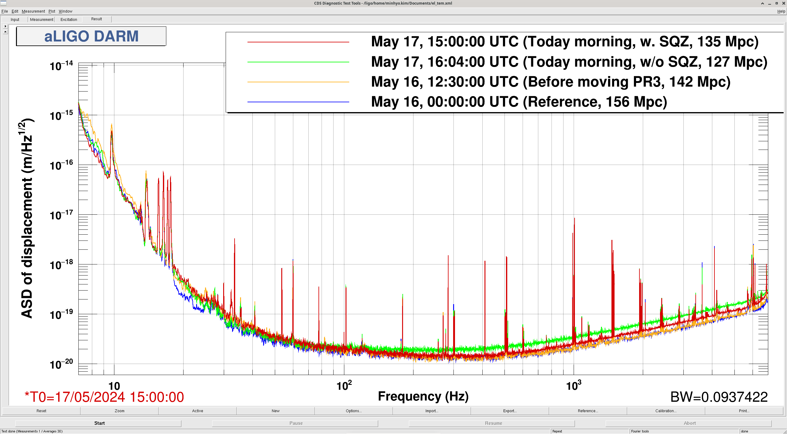
Checked for the reason of large BNS range drop (Sheila's alog: 77870), with comparing DARM plots (screenshot).
From the DARM comparison, it seems that the low frequency noise went worse right before PR3 alignment change, which correlated to the range drop before yesterday's commissioning (156 Mpc -> 142 Mpc). On the other hand, high frequency noise went worse after relocking using PR2 changed alignment. Seems that at both frequency range got worse with unknown reason (maybe SQZ).
While Sheila tried to fix SQZ, she suggested adjusting A2L gain value of ITM and ETM. After I finished with P2L decoupling of ITM, we had lockloss.
Images attached to this report
Comments related to this report
Before the lockloss, ITM P2L gain changed to:
| Channel | Before | After |
| ITMX | -1 | -1.005 |
| ITMY | -0.396 | -0.355 |