Jennie W, Sheila
Summary: We need to rerun this test with slightly different starting QPD offsets and a different amplitude to get a meaningful measurement of how the optical gain would be affected by changing the OMC alignment.
I started an injection into the OMC ASC loops (which feed back to the OMC and the OM3 pitch and yaw to keep the beams centred to specific offsets on OMC QPD A and B.
With this we can raster the OMC alignment and find which QPD offsets allow us to maximise optical gain.
The injection started at about 20:30 UTC while no squeezing was injected.
I used this template at /ligo/home/jennifer.wright/Documents/OMC_Alignment/20240419_OMC_Alignment_EXC.xml with amplitudes of 3 counts in all four degrees of freedom.
Within one cycle the OMC suspension saturated.
Why did we saturate with an injection amplitude of 3 as this ran the last time we did this test without any saturations?
Decreased amplitude to 1 to run it without saturating the OMC suspension.
Restarted at 20:39:07 UTC roughly.
Stopped injecting after 21:06:00 UTC.
Results inconclusive as changing the QPD in offset does not seem to change the noise injected around the calibration line between 410 to 411 Hz, so maybe we need to have higher injection amplitudes but start raster from different QPD offset set points so we don't staurate the suspension.
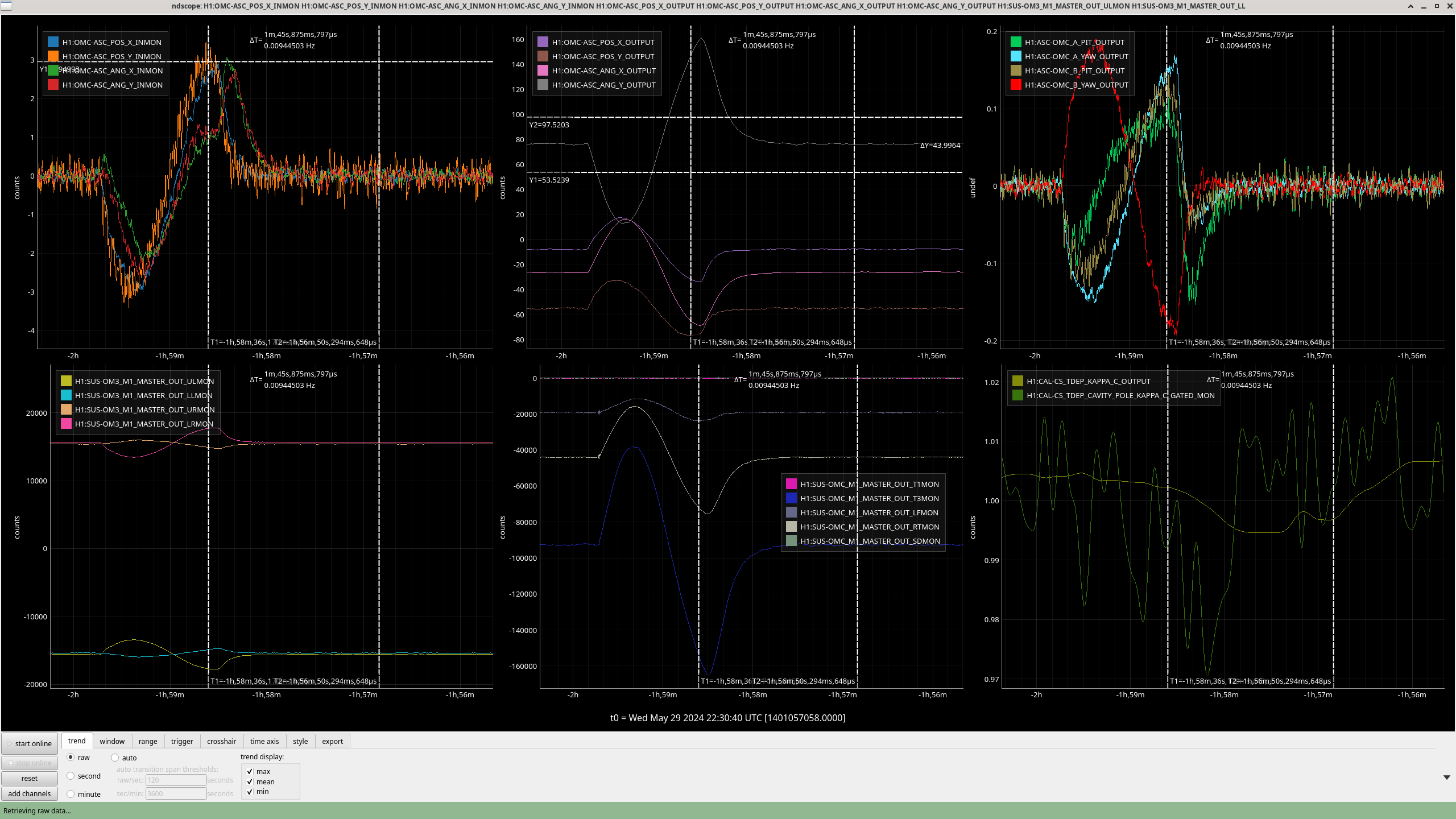
Looking at ndscope of the channels when they saturated.
OMC T2 and T3 saturated (this is an18 bit DAC). This is OMC pitch degree of freedom, which corresponds to Y direction in the OMC ASC loop basis.
Looking at the top left plot the POS Y DOF seems to correspond to the time of saturation and is the highest Y channel so we want to put in a +0.5 offset to this before the next time we run this raster to bring the input to the POS Y loop down in magnitude.
I forgot to post the the results from yesterday.
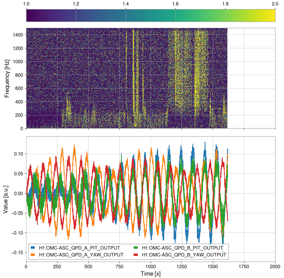
As can be seen from the spectrogram while we were doing the OMC alignment scan, there were a lot of glitches during this period which may limit us in using the BLRMS as a measurement of optical gain as some of these glitches were at both BLRMS frequencies we look at - ie. 410 - 411, 800 - 900 Hz.
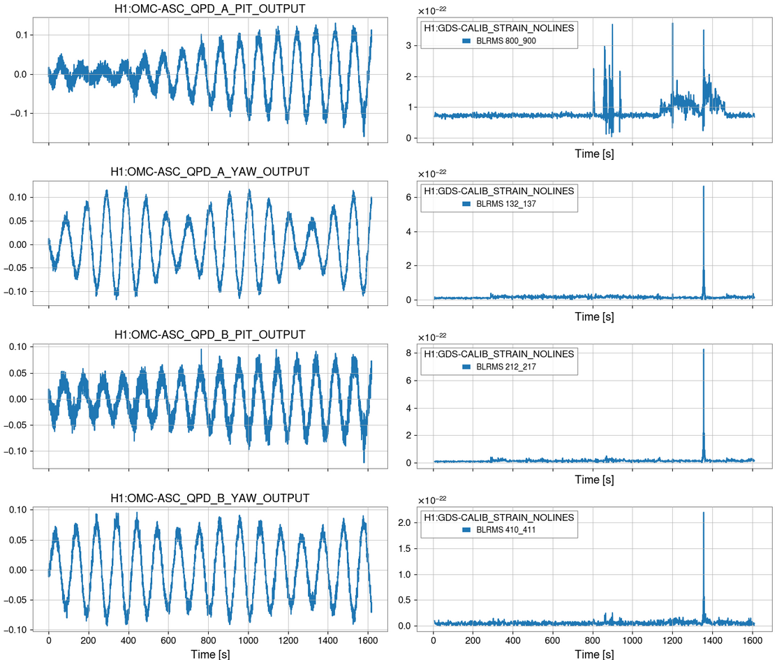
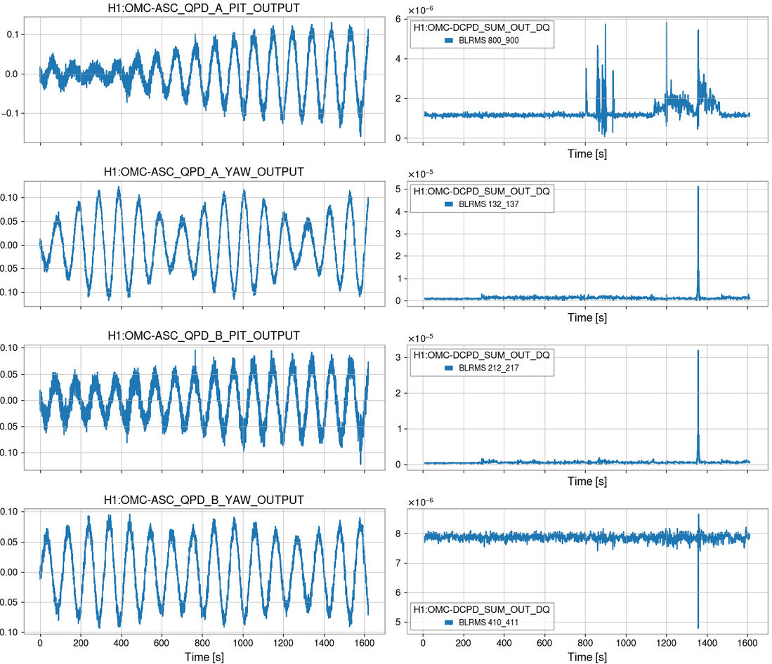
Looking at zoomed in time series of GDS calib strain and OMC DCPD these glitches can also be seen.
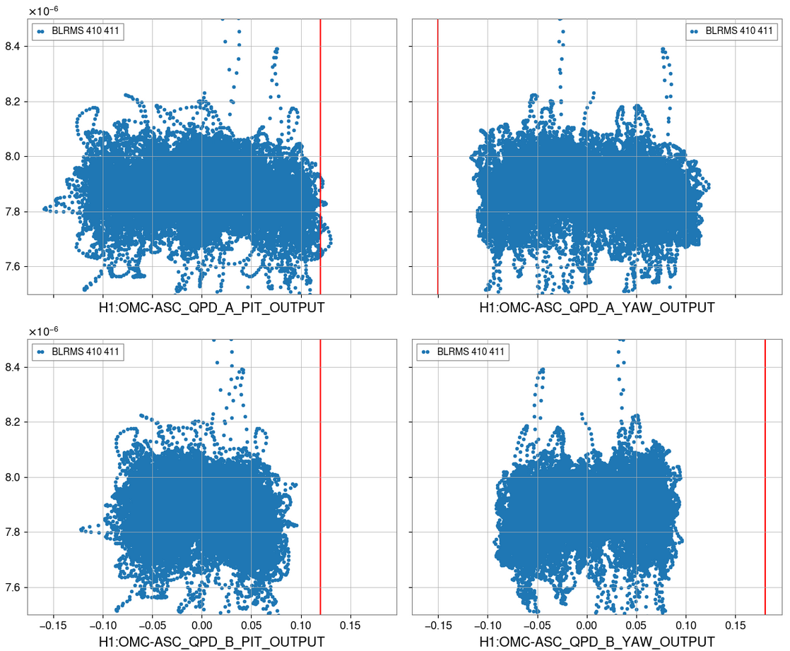
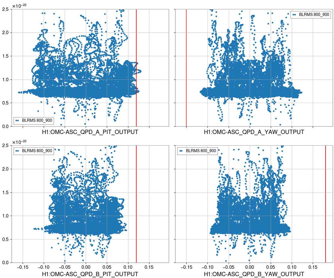
The plot of OMC DCPD BLRMS at the calibration line frequency against QPD offsets seems to show they are quite flat in frequency and so we can't get any gain from adjusting the QPD offsets at this alignment into the OFI.