Sheila, Jennie W, Jenne D
Peter F suggested we dither the alignment into the OFI and look at the power fluctuation on our QPDs and diodes in HAM6.
If we are right on top of some trough in OFI throughput thewn we should see a 2*f_dither line in our QPDs and PDs.
If we are on the side we should see f_dither frequency lines, and away from the bad spot on the OFI we should see no modulation at either of these frequencies.
We had trouble finding the centre of the bad spot with this measurement although it did tell us some more information about how steep it edges are.
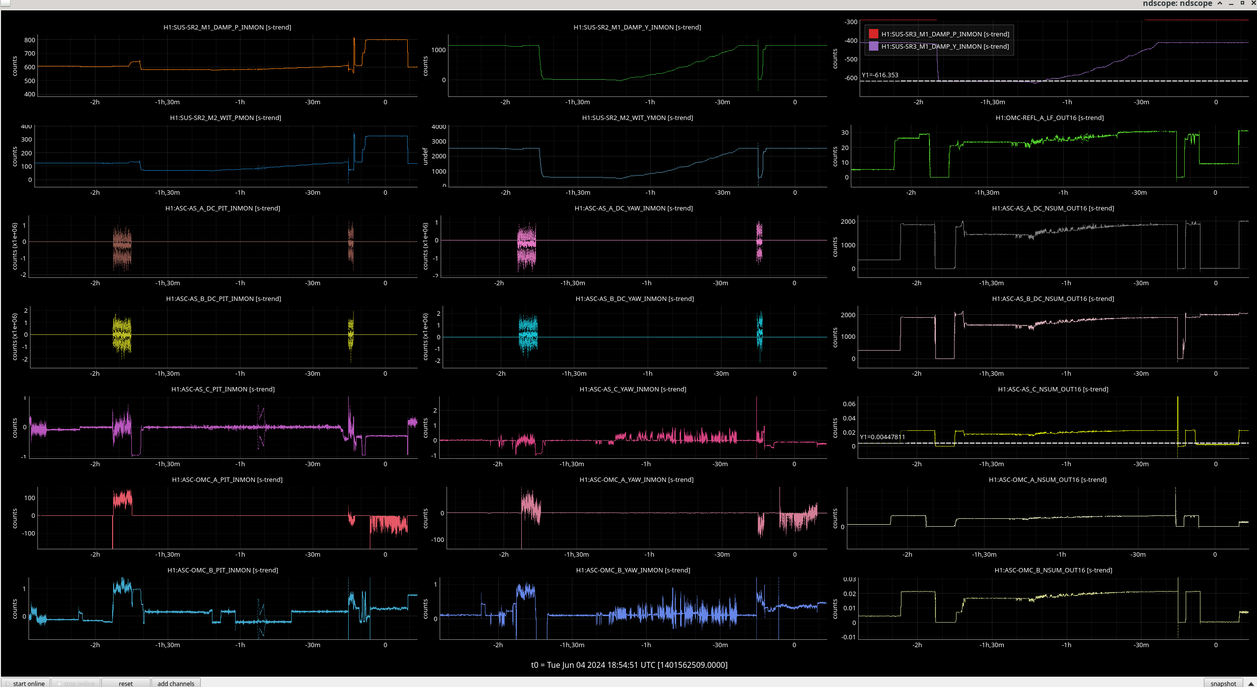
See the below image for the channels we were monitoring.
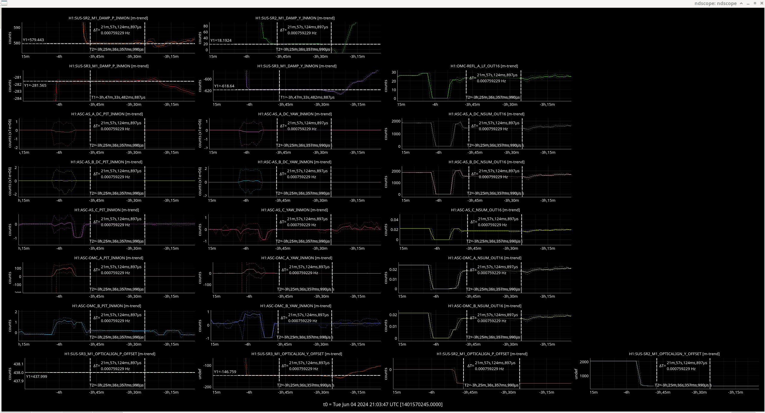
We set the sliders to the 'bad spot' ie. our alignment into the OFI that was nominal before April 24th this year shown in the first table column here.
The values we used were:
| H1:SUS-SR2_M1_DAMP_P_INMON (SR2 P osem) | 579 urad |
| H1:SUS-SR2_M1_DAMP_Y_INMON (SR2 Y osem) | 18 urad |
| H1:SUS-SR3_M1_DAMP_P_INMON (SR3 P osem) | -282 urad |
| H1:SUS-SR3_M1_DAMP_Y_INMON (SR3 Y osem) | -619 urad |
We turned the dither lines on the third stage down on SR2 (11 Hz for pitch degree of freedom and 13 for yaw).
The channels used were H1:SUS-SR2_M3_TEST_P_EXC and H1:SUS-SR2_M3_TEST_Y_EXC with a sine wave injection of 1000 counts amplitude.
We set the IFO_ALIGN guardian to SR2_ALIGN which feeds back to SR2 on its own to keep the beam centred on AS_C QPD, this means we only had to change the position of DSR3 and SR2 would be stepped by this loop (SRC2).
We also turned on the centering loops, then the OMC ASC, but had to turn the OMC ASC off for some of the measurement period as OMC suspension kept saturating.
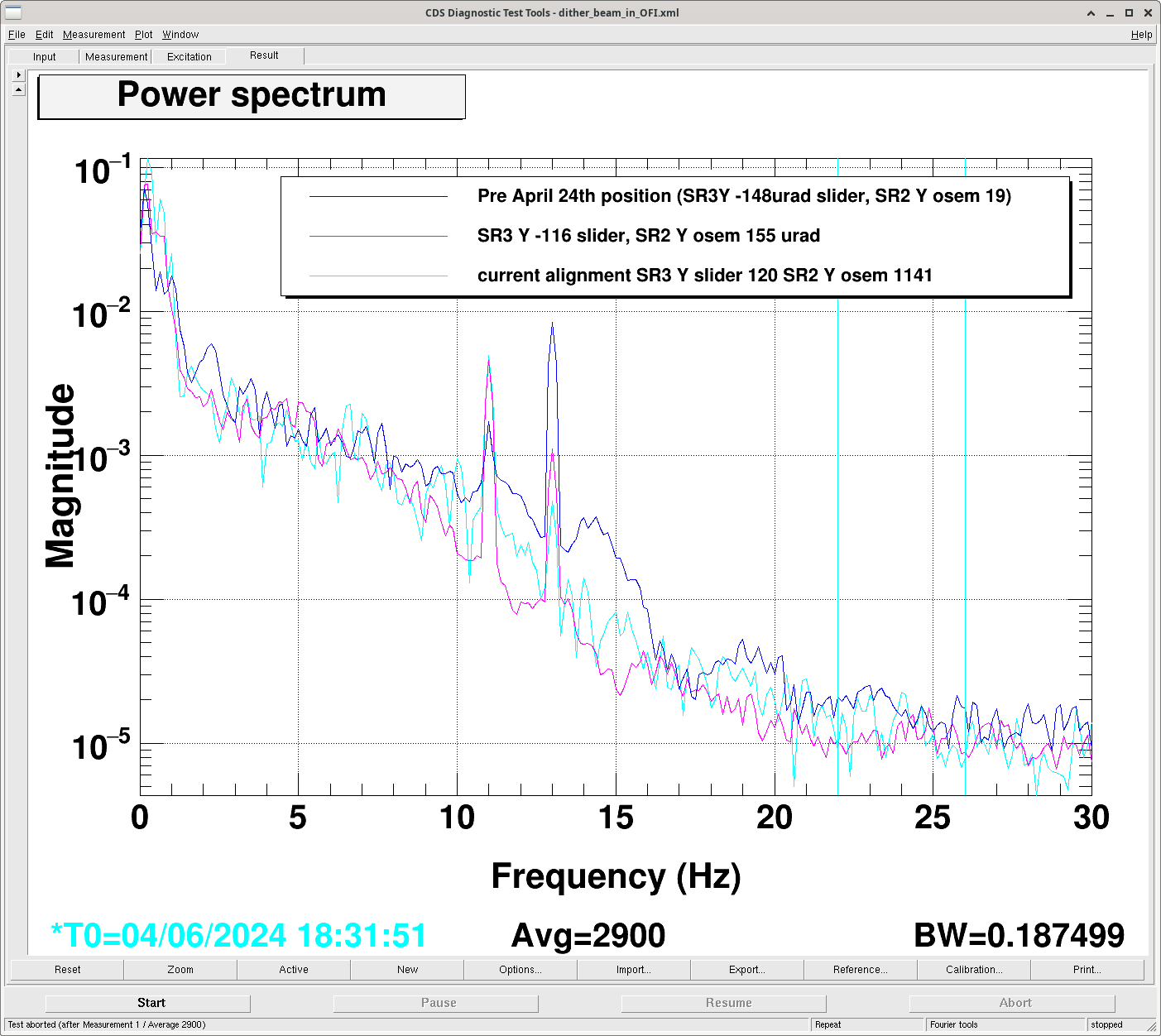
17:16:48 UTC went to bad spot mentioned in table and tried dither - did not see 2F modulation in power on all five HAM 6 QPDs or the OMC REFL PD (shown here as dark blue reference).
This time is shown by the position (roughly) of the first cursor in this image.
We eventually saturated the SR2 suspension when driving it in pitch and still don't see 2*f_dither peaks.
Now walking the beam from this position at around 17:34 UTC.
The magenta curve was taken after we had moved in the positive yaw direction to have the SR3 yaw slider at -116 uradians and the SR2 yaw osem to be at155 uradians. It can be seen that the pitch line gets higher and the yaw line lower so this means we are moving away from the centre of the bad spot in yaw and towards it in pitch as we moved the beam in this direction on the OFI.
We ran OMC ASC again to centre on OMC REFL as this dropped but then fully saturated OMC ASC so turned off OMC ASC.
OMC model restarted at 17:52:45 UTC and so the OMC ASC restarted with 0 offsets, since we hadn't cleared history this caused oscillation on QPDs for OMC.
We increased the gain in the SRC2 centering loop by increasing the input matrix sleement in SRC2 loop.
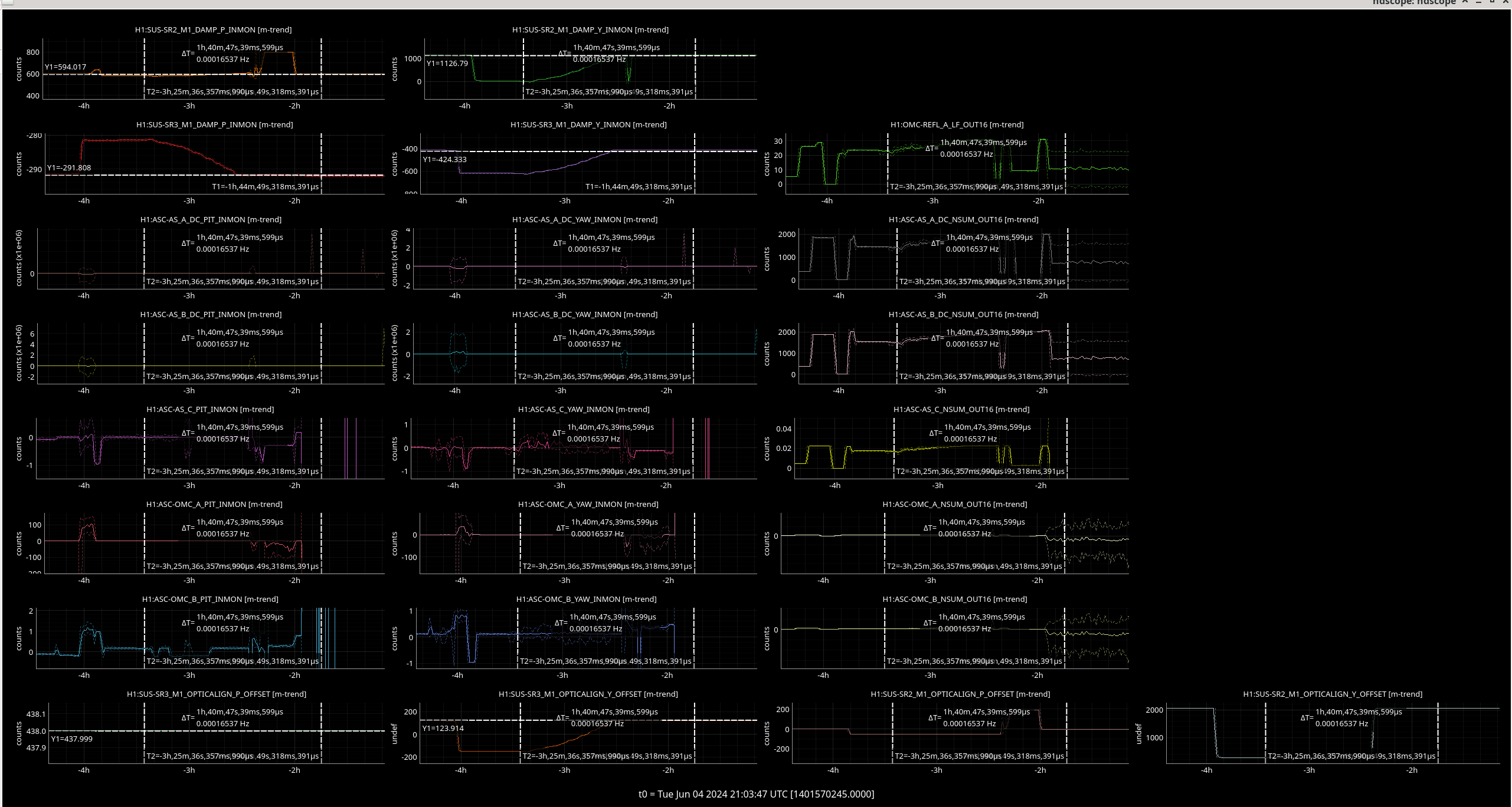
18:45:52 UTC Trying to move to better OFI spot suggested by Alena's calculations but this moves us off AS_C and saturates DC centering so will move us off AS_A and B (if we do this we will need to pico back onto these QPDs).
The light blue curve was taken at our current alignment through the OFI, marked with the second cursor in this image.
The xml file Sheila used for measuring the dither on SR2 is also attached.