Jennie W, Sheila
At the start of the commissioning period we did some OMC Alignment tests to see if this improved our optical gain.
First Sheila turned off injection of squeezing.
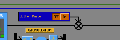
15:32:50 UTC Started OM1 and OM3 dithers at 15:32 UTC roughly from OMC control screen. sitemap -> OMC -> OMC Control then push slider shown in this image to on.
15:32:50 UTC started low frequency OMC ASC dither lines via template at /ligo/home/jennifer.wright/Documents/OMC_Alignment/20240419_OMC_Alignment_EXC.xml
Stopped OMC ASC lines at 16:03:07 UTC.
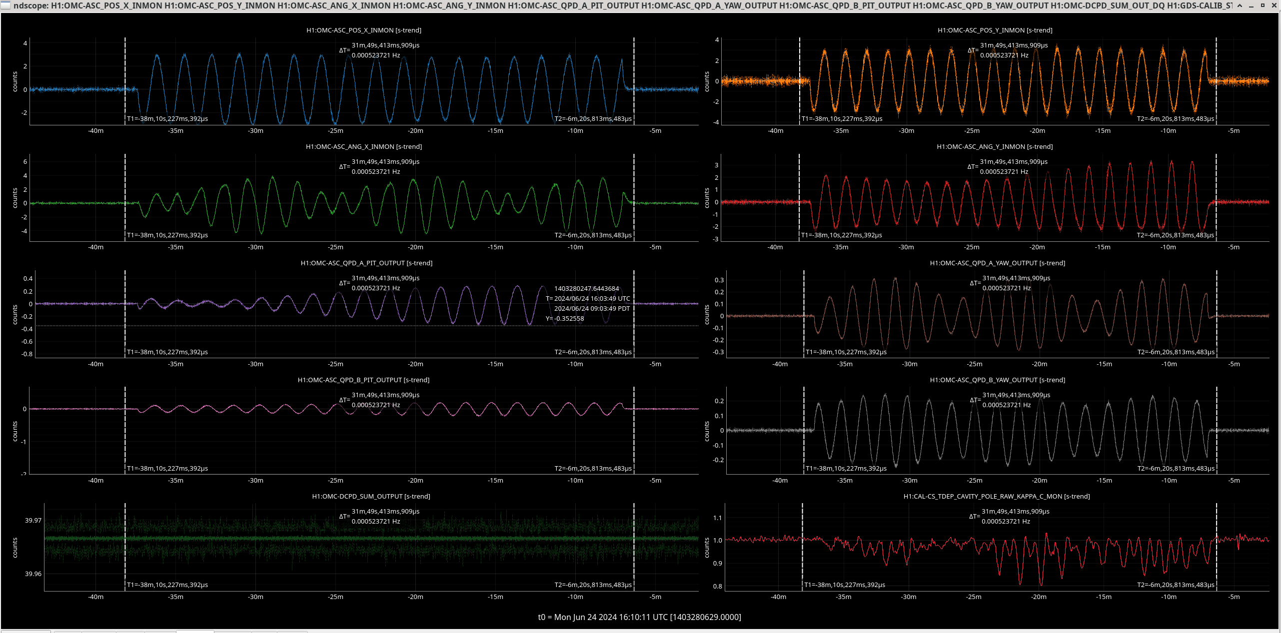
The lines effect on the OMC ASC degrees of freedom and kappa C (optical gain) can be seen here.
Then we re-injected freq dep squeezing.
OM1 and OM3 dither lines were turned off at 16:03 UTC.
After these tests we proceeded to run A2L optimisation recorded here.
To analyse the date I used a version of Gabriele's method where we demodulate OMC DCPD SUM at the OMC ASC dither frequencies and then the 410Hz PCAL line, to see what combination of QPD alignment offsets gives the highest optical gain.
The notebook is at /ligo/home/jennifer.wright/Documents/OMC_Alignment/OMC_Alignment_2024_06_24.ipynb
and can be ran using:
jupyter notebook OMC_Alignment_2024_06_24.ipynb
and then opening the provided link in your browser.
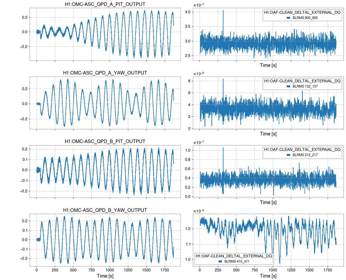
The time series of the QPD offsets being changed are in this image. The right-hand plots show the cleaned DARM time series for different BLRMs regions. It can be seen that the first three have large glitches in the time series, but the 410 Hz one on the bottom right does not and so this frequency should be good for analysis.
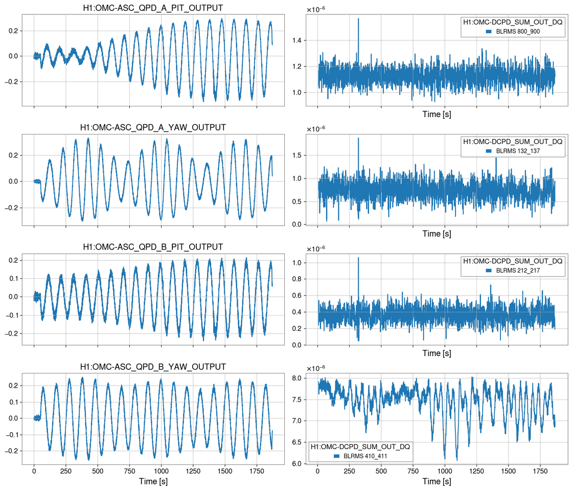
The same plot but using data from the OMC DCPDs in the same frequency regions on the right is here. Again, there are glitches in the other BLRMS frequencies, but the 410 Hz one looks clear.
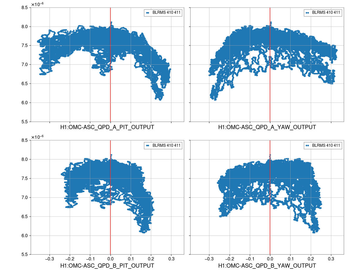
The final plot shows the BLRMS at 410Hz after the double demodulation against the QPD offsets, the red lines are set to be the proposed change in QPD offset. For three it does not look like changing ther QPD offset will improve the optical gain. For the bottom right (H1:OMC-ASC_QPD_B_YAW_OUTPUT) the correct offset change could be 0 or it could be +0.1.
It was decided not to change any of the ASC alignment offsets therefore.