J. Oberling, R. Short, J. Driggers
Summary available at this alog.
Background
Our PMC Reflected Power (PMC Refl) has been slowly increasing for several months, roughly starting in mid-March. There was an unexplained PMC Refl increase near the beginning of the year, but things were mostly calm until the middle of February; we were able to correct this with a remote alignment tweak on Feb 27, 2024, but this is the final time an alignment tweak made any real improvement. We had been able to recover PMC Refl to just under 17.0 W by slightly tweaking the operating currents of the amplifier pump diodes back in April (changing beam quality but maintaining output power), but this did not stop the slow increase in PMC Refl. At the end of May Ryan S. and I went into the enclosure and made some measurements around the PMC. We found the visibility measured at ~91%, while our PMC throughput was down around ~83%; we also inspected the optics between Amp2 and the PMC and found no issues except some residue on mirror M11. We drag wiped this mirror until it was clean but this caused no change in PMC behavior. This indicates a potential issue with the PMC itself, and is very similar to the symptoms LLO saw with the original, glued PMCs back in the O1/O2 era. Oddly enough, after our incursion PMC Refl jumped by ~1.3W, from ~19.7W to ~21.0W, and we could again find no explanation for this jump. Since we could find no other cause for the slow increase in PMC Refl (not alignment, not mode matching, not dirty optics, etc.) we decided at the time to watch how things developed, with the understanding we would likely have to swap in the spare soon (mystery loss was already at almost 8%). The PMC Refl increase flattened out for a couple weeks but started increasing again in the latter half of June, and at a quicker rate than previous, so we decided it was time to swap in the spare; Tuesday morning, right before we started the spare swap, we found PMC Refl had already increased past 23 W (Ryan took that last set of trends during his EVE shift on 7/1).
The Swap
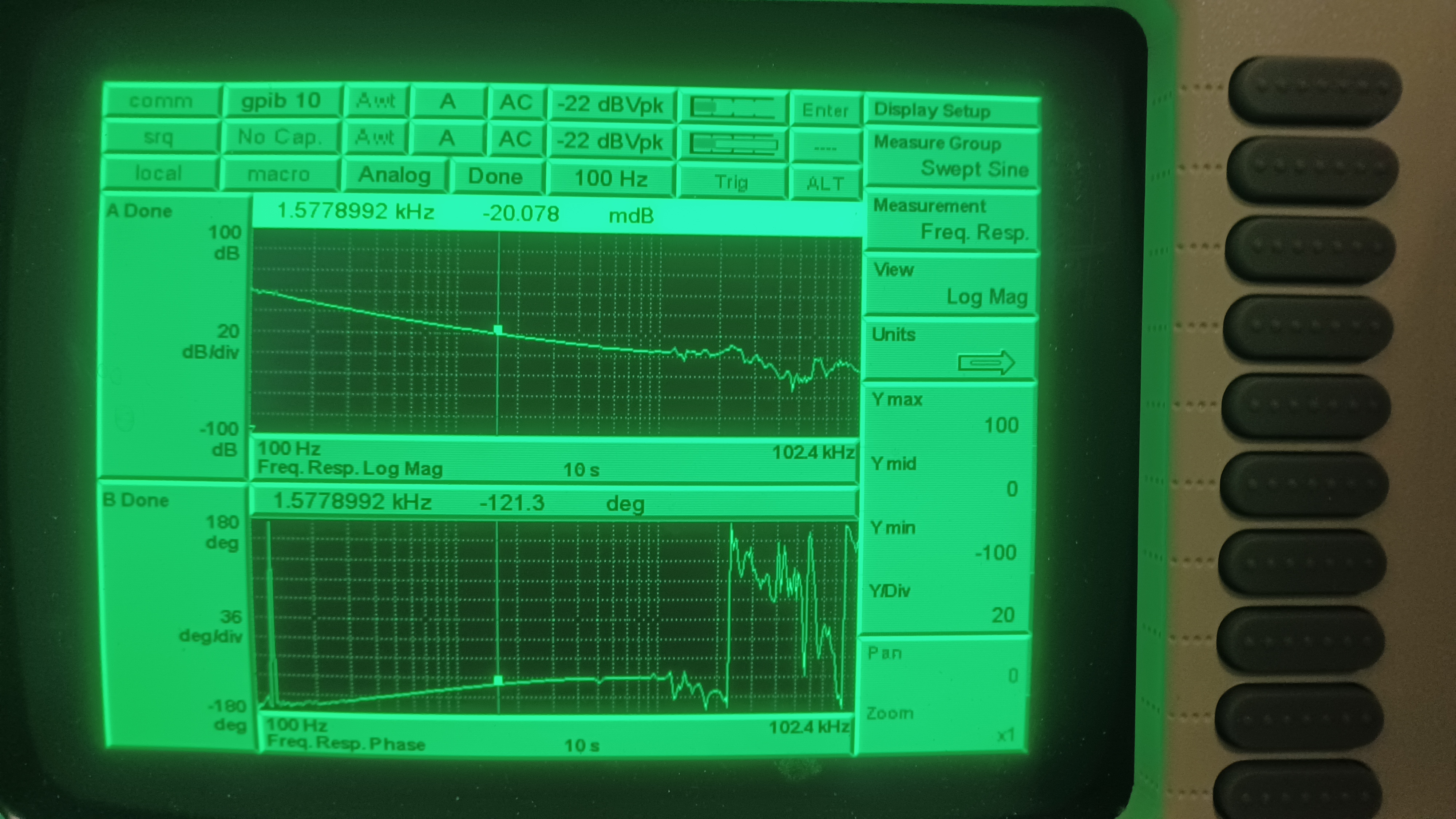
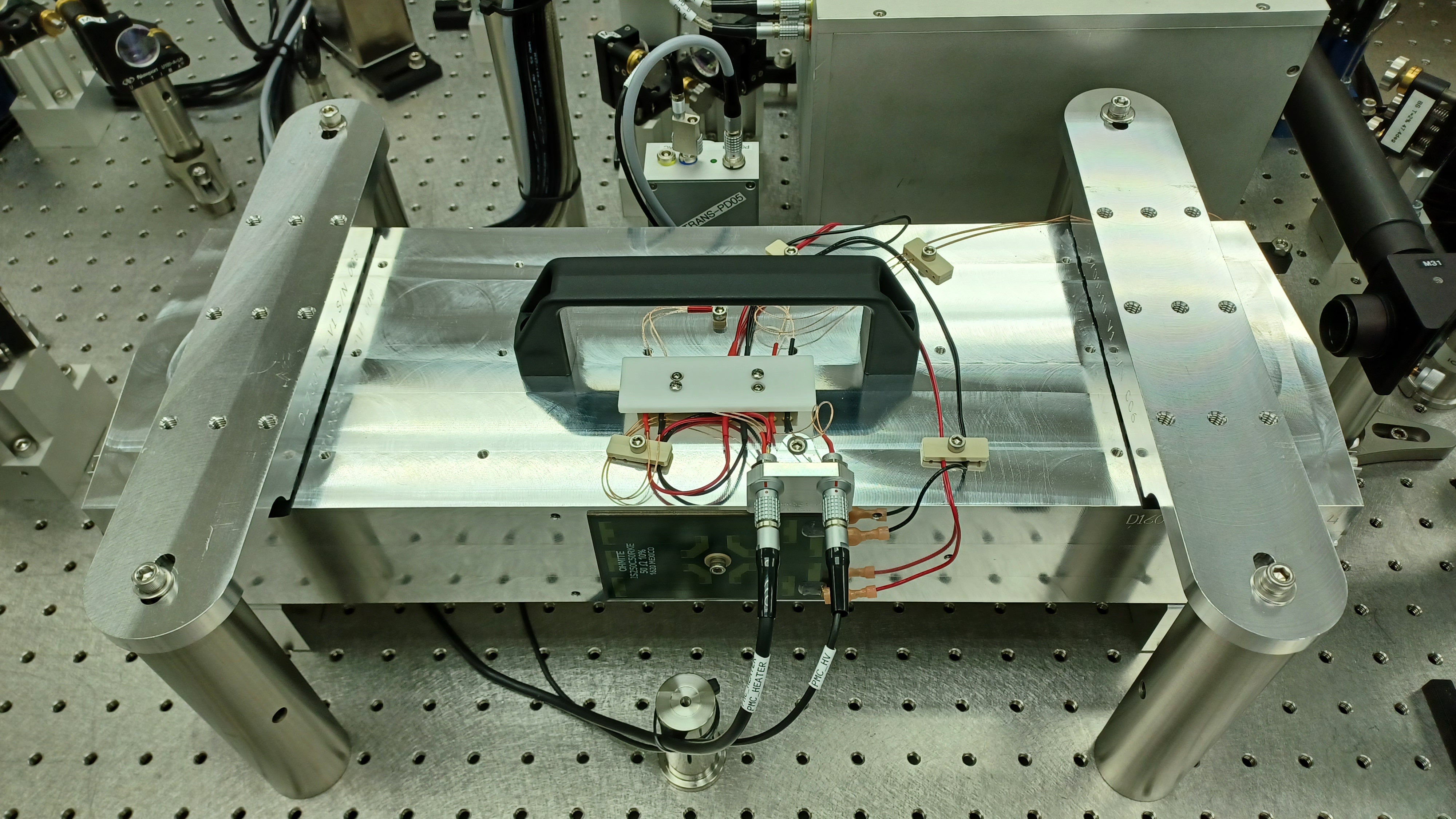
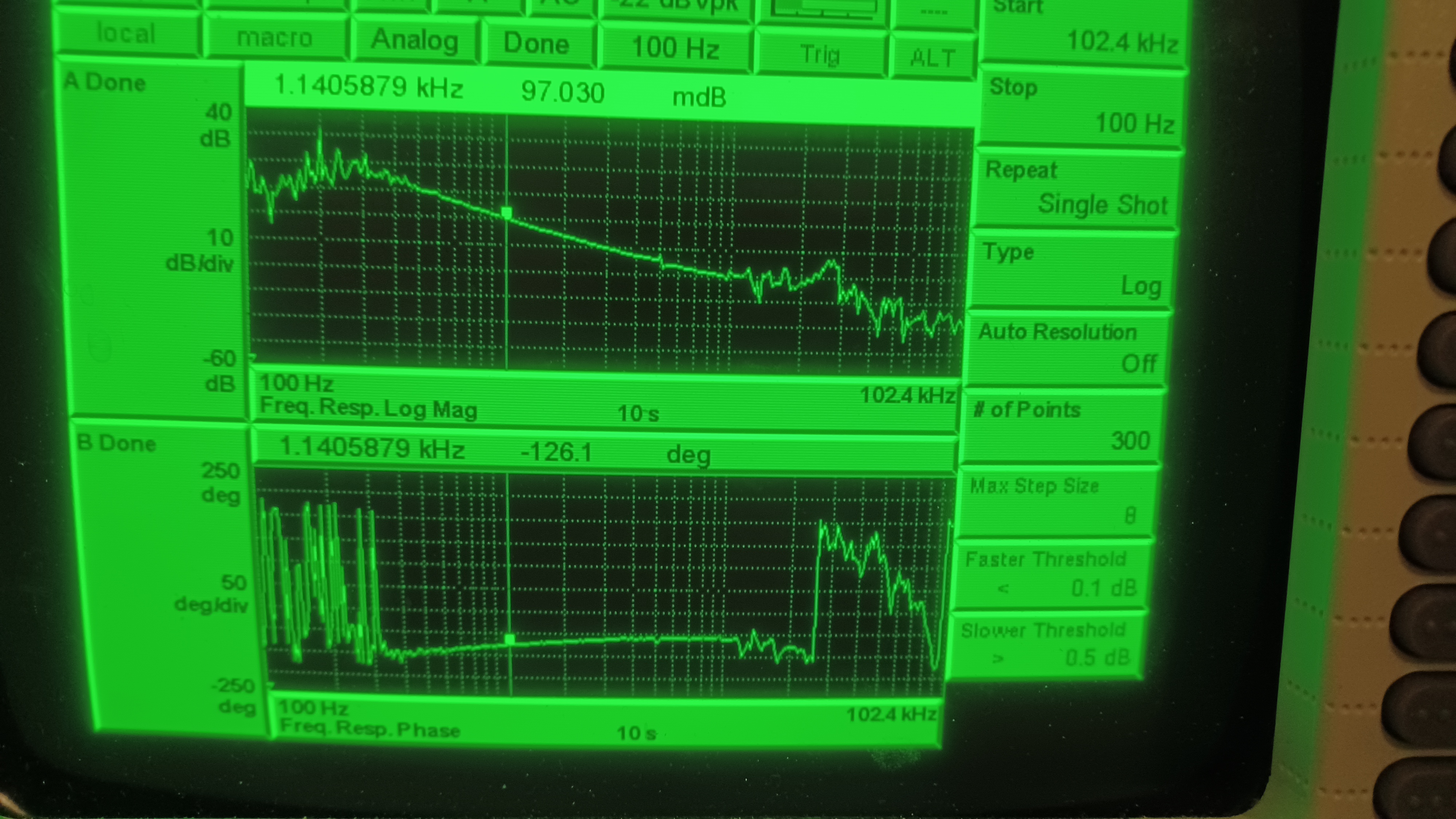
We began by taking a transfer function of PMC SN007 (the old PMC), shown in the first picture. The UGF is a little high (the new PMCs like to be at ~1kHz), but I recall this being the best we could do at the time (we don't have enough electronic gain control to get the UGF to 1kHz by itself, we have to lower the light level on the locking PD to lower the optical gain; this has to be balanced with the dark voltage on the PD, making sure the locked voltage is above the dark voltage). All in all the TF looks normal. We then shut off ISS and FSS, unlocked the PMC, turned off the PMC temperature control loop, and turned off the PMC PZT high-voltage power supply. Time to go into the enclosure.
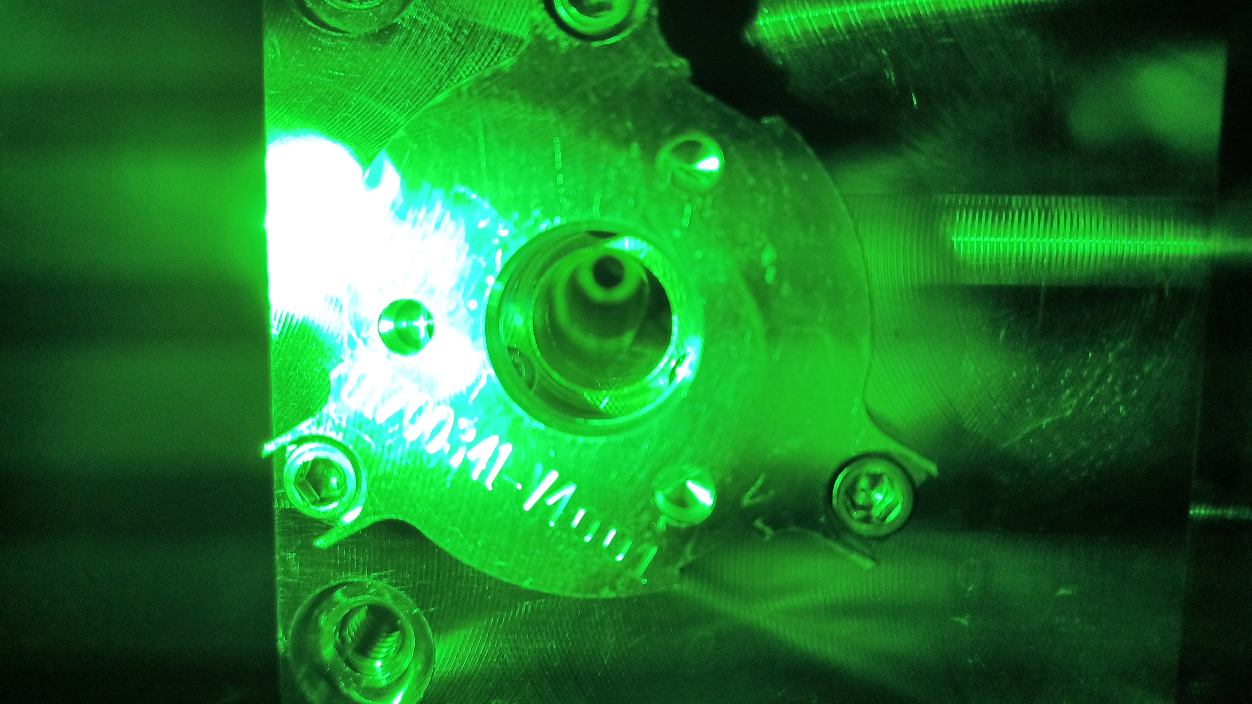
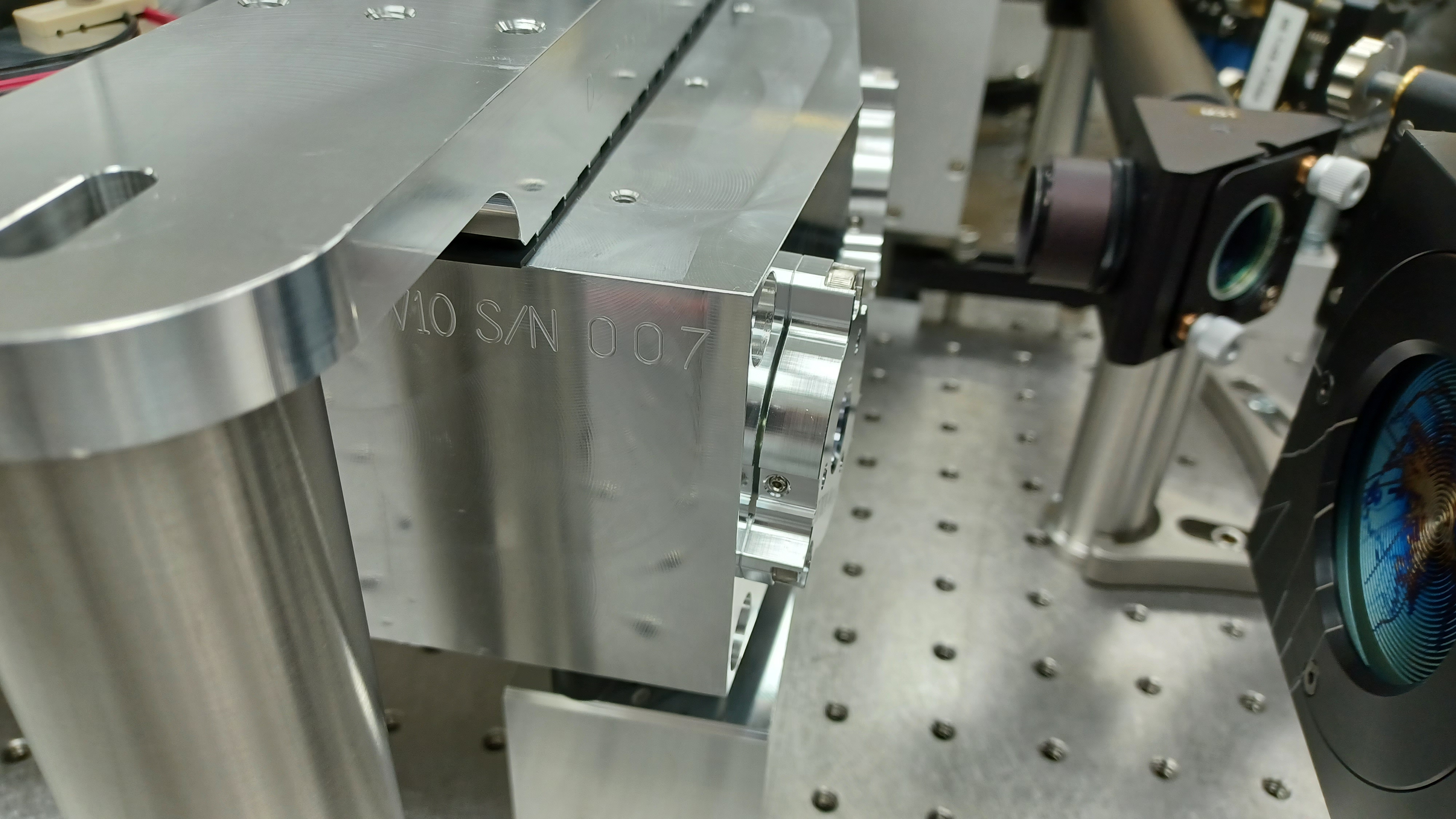
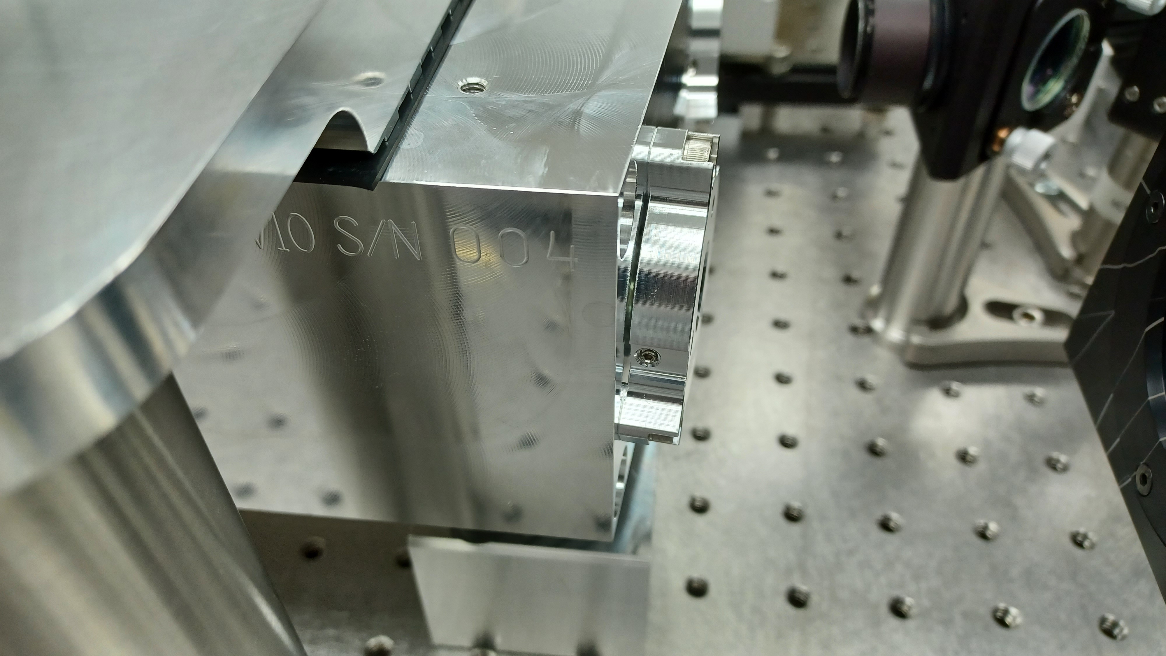
Once inside we used the High Power Attenuator assembly to lower the power incident on the PMC to 100mW, the typical power level used for alignment; this was done as a "just in case" for laser safety reasons. We then unwrapped and inspected the new PMC; it is SN004. Everything, for the most part, looked really good. We did find a small bit of something on the main output mirror (2nd picture), but were able to successfully drag wipe it away without leaving and residue that we could see (3rd picture). We did have to move the insulated cover for the PMC's terminal block from SN007 to SN004 (to keep someone from accidentally touching the PZT high-voltage connector), and had to slightly re-route the PZT wires so they were not on the spot where the damping clamps sit. That done we were ready to swap the PMCs. The new PMC fit nicely into the magnetic base and everything looked nice and even. We installed the damping clamps with the bolts only finger tight to start, plugged in the 2 wires (voltage supply for the heater and PZT), turned on the PZT high-voltage power supply, and proceeded with recovering the PMC. Pictures 4 through 6 show, in order, the old PMC SN, the new PMC SN, and the new PMC freshly installed on the PSL table.
The Recovery
To get enough light on the PMC locking PD to actually lock the PMC we have to raise the incident power to 10 W (and this is pushing it), so we did so. On our first attempt to lock the PMC it would not lock, but we did see a small bit of TEM00 flashing through on the PSL Quad display as the PZT ramped. We routed our spare Lemo cable bundle into the PSL enclosure so we could access the ramp signal, and fired up an oscilliscope to look at the signal on the locking PD. Once we had it triggering on the PZT ramp we could see several smaller peaks flash through, but one slightly larger one that could be our TEM00. I did an extremely small yaw adjustment on mirror M12 (my guess is less than 1/32 of a turn, as it barely moved under my fingers) and the suspected TEM00 peak immediately grew by a large amount. We figured, why not, and tried to lock the PMC; it locked right up without issue, transmitting ~3.5 W out of the 10 W incident. Success! Or so we thought.
We fired up the picomotors on mirrors M11 and M12, and Ryan proceeded with tweaking alignment into the PMC. However, the best he could get was 7.5 W out of the incident 10 W. We measured the visibility at ~95%, while our power throughput was only 75%. Well then.
We began checking everything we could think of: optic cleanliness, beam alignment, took a look at the control loop, PD alignment. Ultimately, we found the beam was misaligned on the locking PD. Once this was fixed Ryan was able to get PMC Trans up to 8.4 W, but that was it. So while better, we still had a throughput of only 84%, and still could find no explanation for the discrepancy between visibility and power throughput. At this point we called Jenne for a consult, get the whole PSL team together. She suggested we check to make sure our locked PD voltage was above our dark voltage, and sure enough it wasn't. I increased the light on the PD until the locked voltage was about double the dark voltage, but this didn't improve the ~10% discrepancy between visibility and power throughput. At this point we figured we had 3 options:
- 1) Try to clean the mirrors on PMC SN004
- 2) Try to clean the mirrors on PMC SN007 and re-install it
- 3) Continue on, carefully increasing incident power on the PMC
Ultimately, we decided on option 3. Assuming we were able to get to full power (spoiler alert, we were able), this would then give us a valuable piece of information: Does the new PMC exhibit the same behavior as the old PMC (the slow increase in PMC Refl)? If it does, then the problem likely isn't with the PMC (although I still struggle to explain the discrepancy between visibility and power throughput in this scenario). At this point we had already overrun the maintenance window by an hour, so we began increasing the power incident on the PMC in steps, checking mirrors for bright spots along the way; we did this slowly out of an abundance of caution, as we did not want to damage this PMC (we don't have a spare for our spare). At each step we measured the visibility (this time properly accounting for the 15 mV of dark voltage on this PD) and power throughput; we only tweaked alignment at the first 10W step and at the final full power step. Power In and Power Out were both measured with our roving water-cooled power meter; the locking PD unlocked voltage was adjusted to approximately -1 V at each power up (the locking PD outputs a negative voltage). The steps:
| Power In (W) | Power Out, Initial (W) | Power Out, Final (W) | Visibility (%) | Power Throughput (%) |
| 10.0 | 3.5 | 8.4 | 94.8 | 84 |
| 20.0 | 17.3 | 17.3 | 96.0 | 86.5 |
| 30.0 | 26.2 | 26.2 | 95.0 | 87.3 |
| 40.1 | 34.7 | 34.7 | 96.1 | 86.5 |
| 60.1 | 52.2 | 52.2 | 96.1 | 86.9 |
| 80.2 | 68.7 | 68.7 | 94.9 | 85.7 |
| 100.0 | 84.9 | 84.9 | 93.7 | 84.9 |
| 128.1 | 104.4 | 105.1 | 89.6 | 82.0 |
At 20 W incident power I noticed a bright spot forming on the PMC input mirror. I kept an eye on it as we powered up, but at 80 W it started to make me uncomfortable so I did a quick drag wipe of that mirror to see if the spot went away. It did not and the PMC behavior was completely unchanged. Ah well.
To end the PMC recovery we took a TF of the new PMC, as shown in the 7th and final picture. Intially we had a UGF of ~2.5 kHz, but this was with our locking PD unlocked voltage still set at 1V; at this setting we had ~ -110 mV on the PD while the PMC was locked, so plenty of room to lower the optical gain. In the end we had a locked voltage of -0.061 V and an unlocked voltage of -0.453 V; this is a visibility of 86.5%, so we definitely have some more optimization to do here (PMC transmission was unchanged after lowering the light on the locking PD). I did not notice this yesterday, but the TF of the new PMC starts getting noisy around 500 Hz, while the old one was pretty smooth all the way to 100 Hz; I also did not notice the difference in y-axis scales until just now as I was uploading these pictures. More indication that we have further optimization work to do here. Finally, we measured PMC Trans and PMC Refl with our roving water-cooled power meter and recalibrated the PD readings in the PMC MEDM; these measured at 105.1 W and 23.0 W respectively. At this point the new PMC was up and running, so we started recovering the other PSL subsystems (chiefly the FSS RefCav).
We started by trying to lock the RefCav, and it would not lock. Dreading the results, I looked at the alignment into the RefCav on our handy alignment iris and yup. Alignment was off. We informed Jenne that RefCav alignment was off, indicating the PMC output was at a slightly different alignment than the old one. This means beam alignment into the IMC (and out of the IMC, as it turns out) and onto ISCT1 was also going to be off, especially as these are both 10s of meters from the PMC (the RefCav is only a few meters from the PMC). Our best guess as to the cause is the mirrors of the new PMC being at slightly different angles compared to the old; this also explains the small yaw shift I had to do to initially lock the new PMC. So Jenne and Sheila worked on recovering the IMC and ISCT1, respectively, while Ryan and I started realigning the RefCav. At this point we were almost 3 hours past maintenance end, so we settled on getting the FSS working under a best effort basis with the understanding we would have to go back in during the next maintenance window to completely tune it up (we have more PMC optimization to do so we already have to go back in on July 9th anyway). In the end we had a single-pass diffraction efficiency for the FSS AOM of 71.7%, a double-pass diffraction efficiency of 69.0%, and a RefCav TPD of just over 0.7 V; we have 263.0 mW input to the FSS AOM and 130.3 mW incident on the RefCav. Not great, but it's working. We forgot, however, to tweak the alignment into the ALS/SQZ fiber pickoff; Sheila was able to temporarily bypass that by lowering locking thresholds for both ALS and SQZ subsystems, and Jenne and I went into the enclosure this morning and tweaked that alignment.
This concludes yesterday's PMC swap saga. I'm keeping WP 11947 open as we still have optimization to do on the new PMC; we also still have to completely tune the FSS path. During this week we will keep an eye on PMC Refl to see if this new PMC exhibits the same behavior as the old one.