Lock loss 1404445312
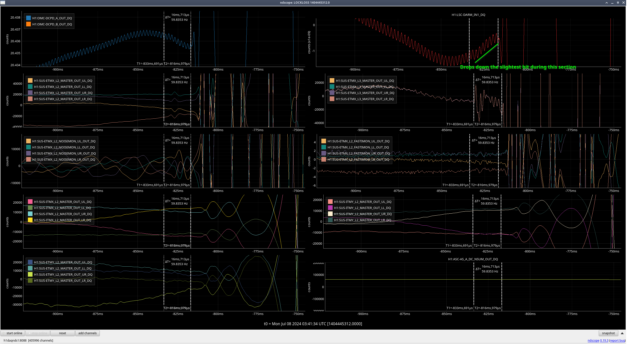
5 hours and 42 mins seems like a standard lock for this week. LSC-DARM saw an odd wiggle before lock loss, normally I see an ETMX output that matches this but I didn't see that this time.
Back to Observing at 0528 UTC.
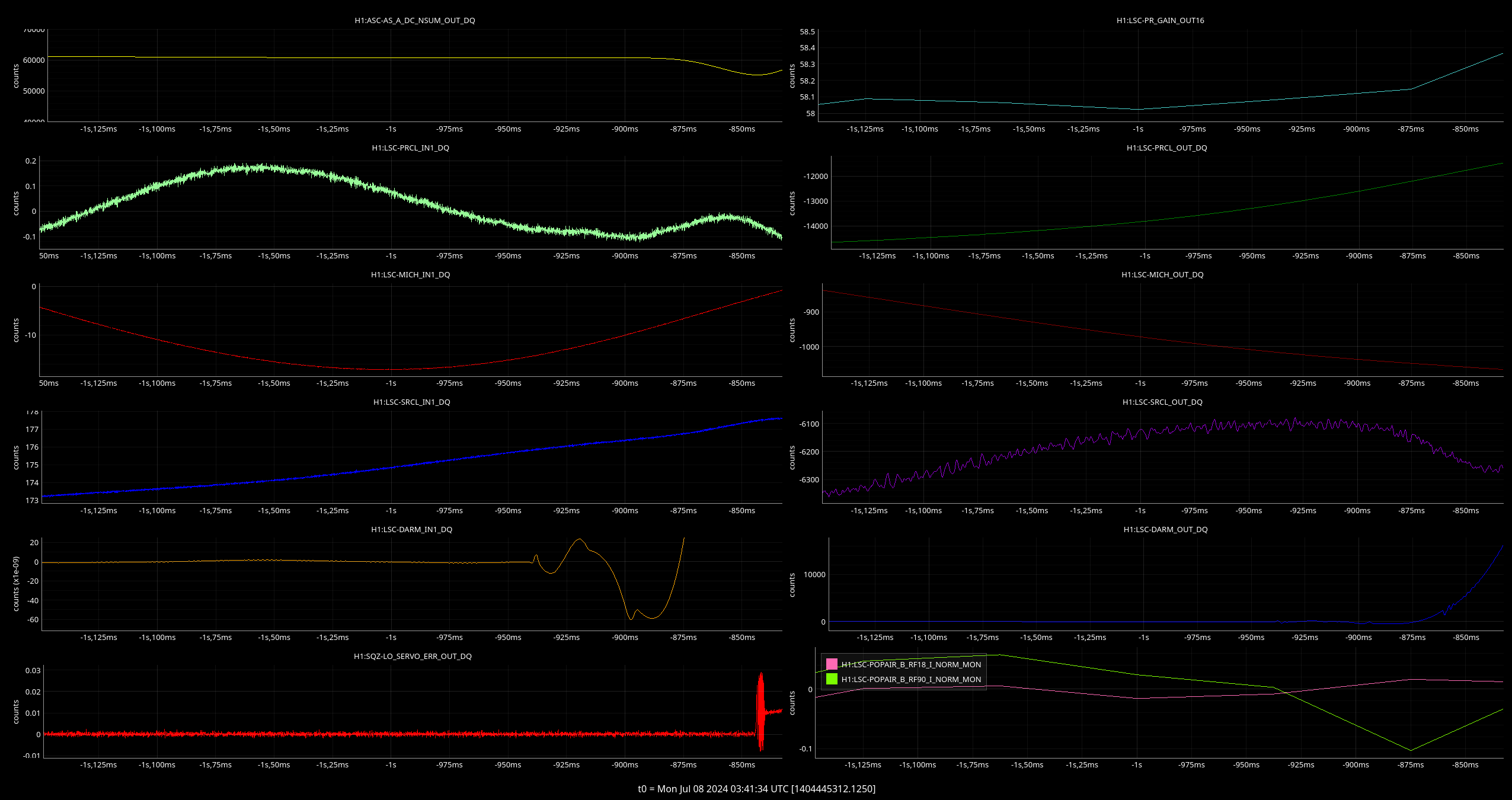
I ended up slightly moving PR3 P from -122.2 -> -121.6 and Y from 98.8 -> 98.6. This brought the beatnote up to around -14.5dBm, up from the -18 or so that I started at, and ALSX power moved up as well. when DRMI locked POP18 looks to be higher than it was the last handful of locks over the last few days. I ran through an initial alignment and then it went right up.
EX L3 does oscillate 16 ms before DARM sees the lockloss, although it might be possible that the slight drop (marked in green) is DARM seeing it??