J. Oberling, R. Short
Today we worked to better optimize the PSL's stabilization systems (PMC, FSS, ISS) after last week's PMC swap.
PMC
We found PMC Refl at ~21 W this morning, when we had left it ~23 W at then end of maintenance last week. The drop is due to the enclosure settling after having the environmental controls on for almost 7 hours (this is normal behavior). PMC Refl had been drifting between 20 W and 21 W since settling down after our incursion, and we did not see a sharp increase over the last week as we had been seeing with the previous PMC. This is good news, but we will continue to monitor this as the slow increase in PMC Refl took place over many weeks.
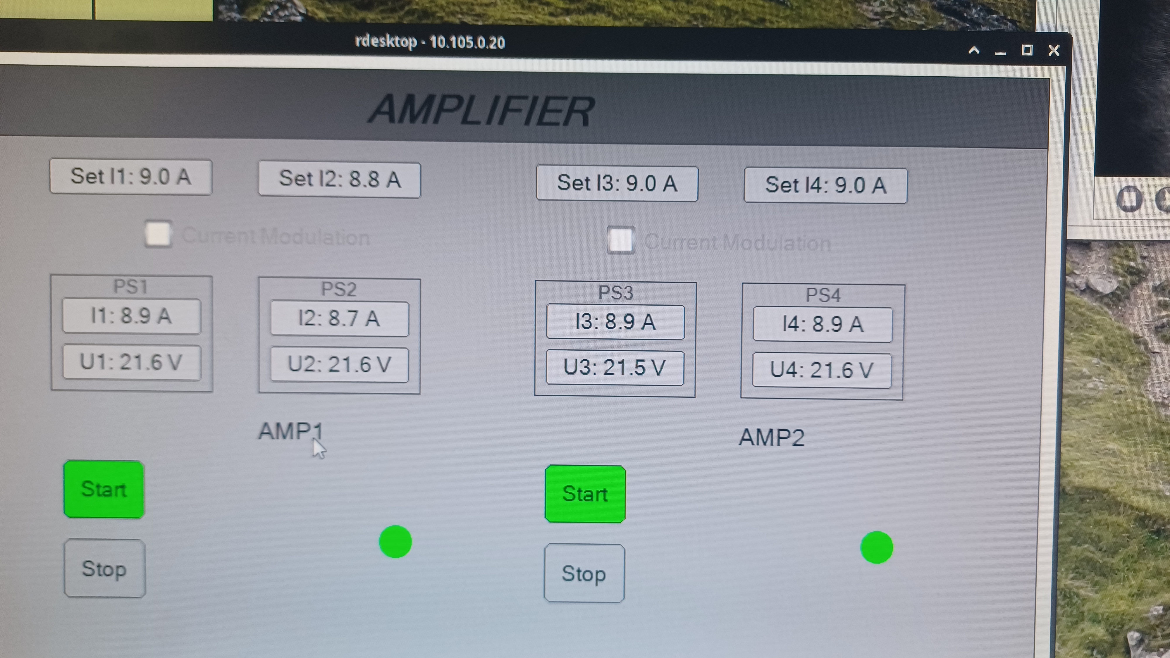
We began by adjusting the operating currents of the PSL pump diodes, as these have a large affect on the output beam quality; this work was done with the ISS OFF. We had adjusted these while PMC Refl for the old PMC was increasing, so it made sense that they would be off with the new PMC. We found that this PMC really likes Amp1 to be pumped less and Amp2 to be pumped more. In the end we had PMC Trans at ~108 W and PMC Refl at ~17.8 W. The pump diode currents are shown in the first picture and given here:
- I1: 9.0 A
- I2: 8.8 A
- I3: 9.0 A
- I4: 9.0 A
With these pump diode currents Amp1 is outputting ~65.5 W and Amp2 is outputting ~138.0 W (Amp1 output down a little while Amp2 is unchanged). Interesting note, lowering the pump diode currents for Amp1 (and therefore lowering its output power) did not have a large affect on the output power of Amp2, and increasing the pump diode currents for Amp2 did not have a large affect on its output power but did have a large affect on PMC Refl (0.1 A changes resulted in PMC Refl changes of 1.0 W or more).
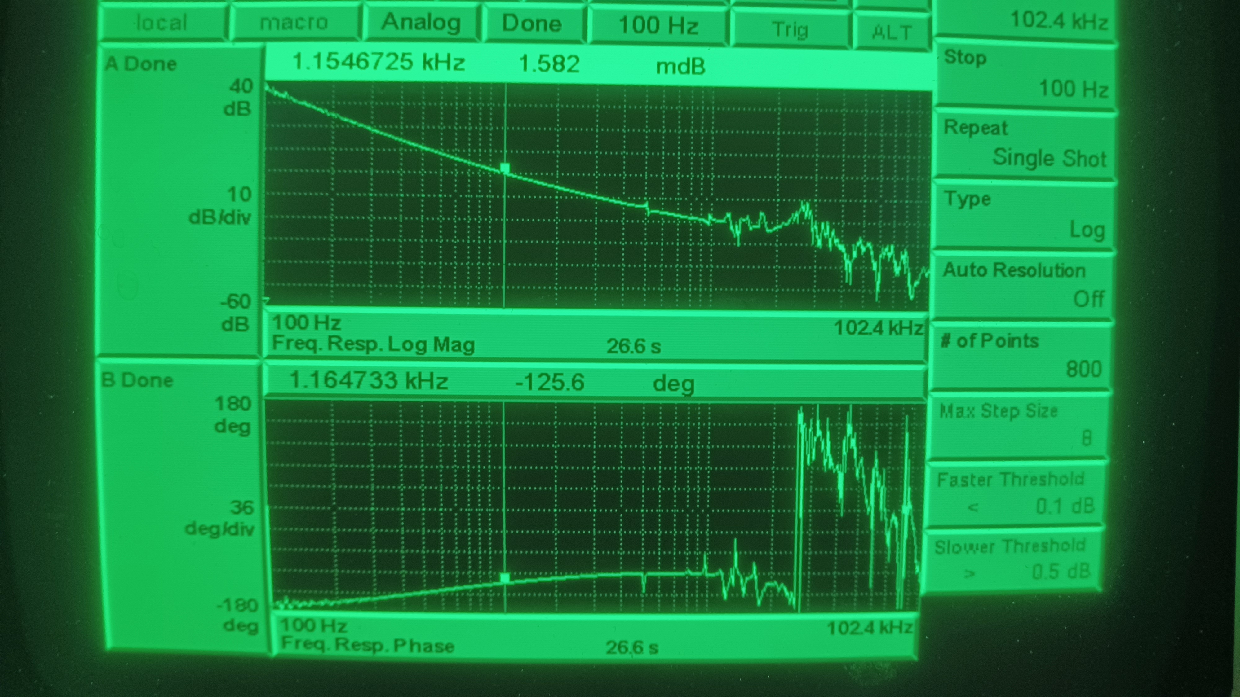
We then went to the LVEA and took a TF of the PMC, results shown in the 2nd picture. UGF is ~1.15 kHz and phase margin is 54.4 degrees. Also, with the enclosure environmental controls OFF the TF is much smoother than the first one we took after the swap (with the environmental controls still ON). Good to see things looking better here. This done we went into the enclosure to tune the ISS and FSS. In discussion with Jenne we decided to wait on tweaking the mode matching lenses until we have done a PMC sweep to see what our mode content looks like.
ISS
We opened up the ISS box to tweak the power on the two ISS PDs. The ISS likes the PDs to output 10 VDC, so the ISS box's internal half-wave plate was adjusted until PDB (which usually reads a little higher) was outputting roughly 10 V. The alignment on each PD was tweaked; PDB was well aligned but PDA was a little off. After tweaking the alignment both PDs read closer to the same value than they have in a while (the BS that splits the light to both ISS PDs isn't an absolutely perfect 50/50), so that's a nice improvement. The final PD voltage values are:
- PDA: 9.93 V
- PDB: 9.98 V
This done, we shut the ISS box and moved on to the FSS.
FSS
The FSS tune up was done with the ISS ON and diffracting ~3% (RefSignal set to -1.99 V); this is done to keep measured power levels stable and helps to speed up the alignment (hard to align an AOM when the power is jumping around). As usual we began by taking a power budget of the FSS beam path, using our 3W-capable Ophir stick head:
- FSS In: 285.6 mW
- AOM In: 283.4 mW
- AOM Out, SP: 194.0 mW
- SP Diffraction Efficiency: 68.5%
- AOM Out, DP: 133.5 mW
- DP Diffraction Efficiency: 68.8%
- EOM Out: 131.7 mW
We then set about tweaking the beam alignment to increase both the single- and double-pass diffraction efficiencies, as these are both regularly above 70%. There was a change in power state between the initial power budget and our adjustments. We tweaked the HWP WP05, which controls the input polarization of the FSS (WP05 is used in combo with PBS01 to set horizontal polarization w.r.t. the table), and upon re-checking the FSS input power it had "increased" to 292.8 mW. We've seen this with these little Ophir stick heads before. Their small size is very convenient for fitting into tight spaces, like found in the FSS beam path, but they come with drawbacks. They aren't the most stable in the world, and they are VERY angle of incidence dependent; we usually have to spend some time aligning the stick head to the beam to ensure it is as perpendicular as we can get. My guess is this is what happened here, we thought we had it perpendicular when we did not. We confirmed our FSS In and AOM in powers made sense and moved on with the alignment. We tweaked the AOM alignment to increase the single-pass diffraction efficiency, tweaked mirror M21 to improve the double-pass diffraction efficiency, and ensure we were not clipping on the FSS EOM (provides the 21.5 MHz PDH sidebands for locking the RefCav). Our final power budget:
- FSS In: 292.8 mW
- AOM In: 290.3 mW
- AOM Out, SP: 210.8 mW
- SP Diffraction Efficiency: 72.6%
- AOM Out, DP: 148.1 mW
- DP Diffraction Efficiency: 70.3%
- EOM Out: 148.1 mW
We did have to move the EOM a little to re-center its input and output apertures on the beam. We then adjusted mirrors M23 and M47 (these are our picomotor equipped mirrors) to align the beam to the RefCav using our alignment iris (use M23 to the front of the iris, M47 to the back) and locked the RefCav. The picomotors were used to tweak up the beam alignment into the RefCav; we started with an initial TPD of ~0.63 V and ended with a TPD of 0.793 V. The beam alignment on the RefCav RFPD was then checked and tweaked, and we took locked and unlocked voltages for a visibility measurement:
- Unlocked: 1.185 V
- Locked: 0.272 V
- Visibility: 77.0%
The visiblity here is a little lower than its norm, which generally hangs out in the lower-80% range (last couple of FSS tune ups had visibility around 83%). Best guess here is a combo of mode matching changes (some evidence of the output mode of this PMC being slightly different from the old) and not quite tweaked up alignment (hard to get the alignment really good while in the enclosure with environmental controls on). Seems there may be some room for mode matching improvement to the RefCav, as both the visibility and TPD are lower than we've usually see after a tune up. Power in the FSS beam is also a little lower than usual (generally around 300 mW, as seen above it's closer to 290 mW now), which also contributes to this. This being the best we could do with what we currently have in the time alloted, we left the enclosure. We'll probably have to do some remote alignment tweaks to both the PMC and RefCav at a later date, once the enclosure is at a better thermal equilibrium. We left the enclosure ACs running for ~15 minutes to bring the enclosure temperature down to its usual ~71.4 degF temperature (as measured by the Table South temperature sensor), and then put everything in Science mode and left the LVEA.
Once back in the control room we turned the ISS back ON. It was already diffracting close to 2.5% so we left the RefSignal alone. Watchdogs were re-enabled and Ryan performed a rotation stage calibration, and we handed things off to TJ for IFO recovery. This closes WP 11947.
We will continue to monitor PMC Refl with this new PMC over the coming weeks.