[JoeG, Keita and Kiwamu]
We continued working on the HAM1 installation this afternoon. All the optics except for the detectors are now on the table including the newly installed QPD sled. We removed the counter weights although didn't check the table level yet.
Besides, there are two (unhonourable) highlights to mention from today's HAM1 incursion.
- The mirror of a tip-tilt (RM1) was found to be backward. So we flipped it to the right direction in situ.
- The other tip-tilt (RM2) started showing a too big pitching
A big pitching in a tip-tilt (RM2):
After the removal of the counter weights we went through the alignment process again in the in-vac detector path. The alignment needed a slight touch mainly in pitch. Then we found that RM2, which is a tip-tilt , showed a large pitching so that the reflected beam went too low. Joe tried to correct it by screwing the bottom 8-32 screw further in. This screw is designed such that as we screw it in, the center of its mass changes the pitching of the whole holder (so as to lower reflected beam). We wanted screw it in further but however the screw was too long and in fact it was already touching the back cage. Keita brought a shorter screw which is 8-32 x 1" and we tried this. However sadly it still hit the back cage because of too large pitching. Joe translated the upper blades to the front to separate the back cage and holder further apart, but this didn't fix the issue. Note the mirror holder was picthing in the same direction even without the screw.
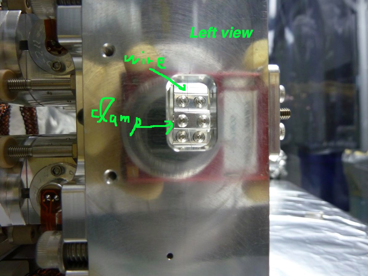
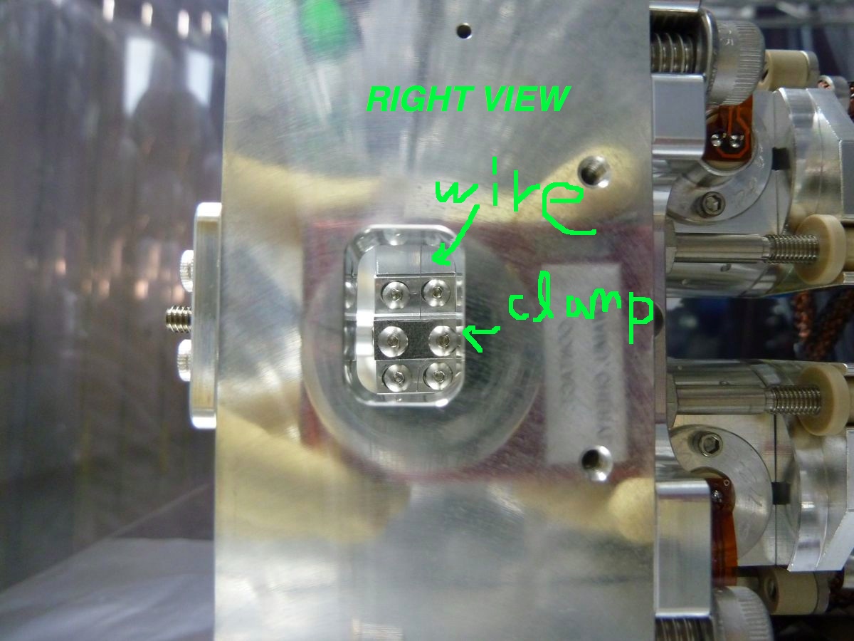
According to our inspection, the clamping point of the wire on the left wire clamp (when looking from the front) on the mirror holder is too close to the back side. Probably about 1 mm off from the center toward the back side. The other side looked also close to the back side but not as big as the left side. At the moment we think this gives such pitching in the mirror holder. Pictures of the clamping point for both left and right sides are attached below. You can see how they are clamped through a rectangular window of the side cage. We have no idea of if it has been like this or when and why this happened. Adjusting the clamping point is certainly beyond what we can do in the chamber because it probably involves with all the alignment and adjustment process. Therefore we removed the tip-tilt our of the chamber. It is now in the clean booth nearby HAM1.
Plan :
Next week we will bring another tip-tilt which was assembled for HAM6 and swap the bad one with it. Hopefully we can smoothly place the tip-tilt and move on to some measurements for checking the mode matching.
Some more pictures are available in ResourceSpace.
The wire not being centered in the clamp is intentional. This is because with the wire centered I found that the tip-tilt mirror tips backwards and it will require some pretty heavy counter balance screw to correct its pitch. At least this is my experience. I had started with the wire centered and faced this problem. I solved it by displacing the wire and then sliding the clamps on the mirror holder to coarse adjust the pitch angle.
Yes, that is correct. The wires are not clamped in the centre of the mirror wire clamp. The Wire Clamping Jig is designed to accommodate this offset in a controlled way. This also includes that there is a 'LEFT' and a 'RIGHT' suspension wire assembly.
I will see to get some dimensions.