hugh.radkins@LIGO.ORG - posted 15:51, Thursday 03 October 2013 (7975)
WHAM6 HEPI Calibration Measurements
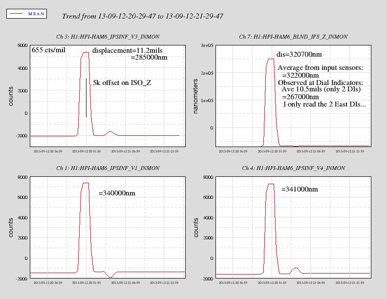
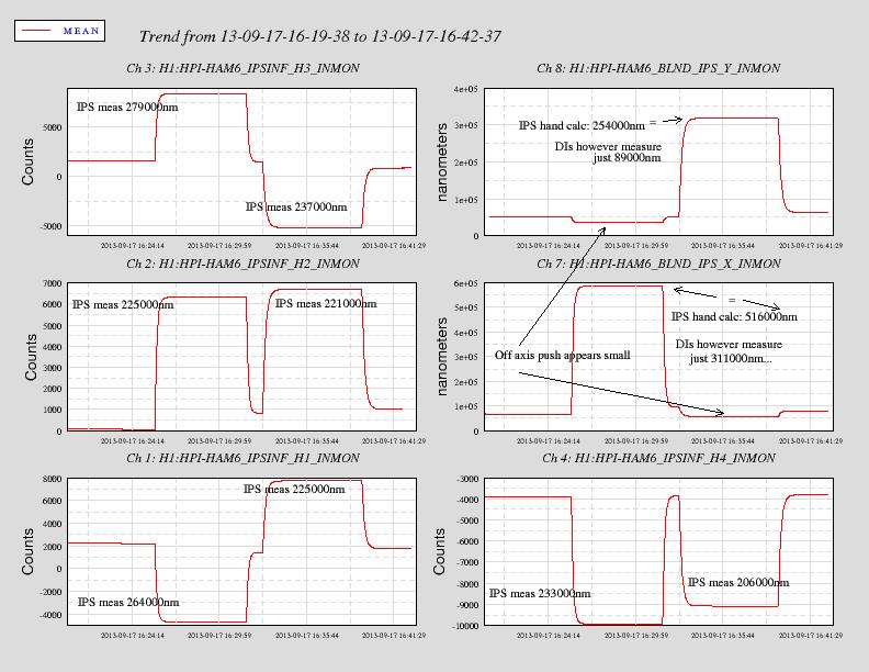
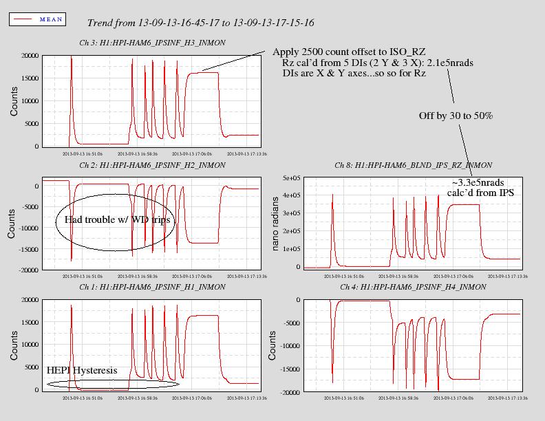
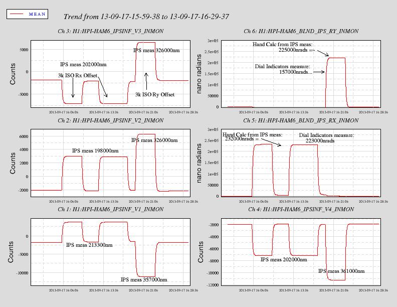
Couple weeks ago before some holiday time I ran some Cartesian DC shifts to confirm my Inductive Position Sensor (IPS) to cartesian input matrix(IPS2CART) numbers.  I have Dial Indicators still mounted on HAM6 so it seemed like a good opportunity to really close the loop on the calibrations.
Attached are four data viewer trend plots showing the IPS raw count readings and the calculated cartesian moves based on the IPS2CART numbers.  The four plots show the vertical drive to Z result, the horizontal to X & Y results, the horizontal to Rz result, and the vertical to Rx & Ry results.
The calibration chain is the counts are converted to nm with FM1 in the IPSINF filter bank.  The nanometers then go through the IPS2CART matrix to apply the sensor/cartesian angles and moment arms where required to get nm cartesian or nrads for the rotations.

The Dial Indicators mounts are very close to the ends of the support tubes and are oriented in the cartesian basis.  This compares to the IPS sensors which are mounted out at the piers.  The verticals sensors are oriented in Z but the horizontals sensors/actuators are aligned on the tangential rather than X or Y.  To me this says the DIs are good for X Y Z Rx & Ry but not so great for Rz.  Also, as the the DIS are at the Support Tubes rather than out at the ends of the crossbeam, they are a pretty good indicator of what is actually happening to the platform.

The numbers read from the IPS converted to nm and then to cartesian suggest the filter calibration and the IPS2CART numbers do as expected, no surprise there.
However, the DIs suggest the platform as seen at the ends of the Support Tubes do not move as much as the IPS readings/calibration theory would suggest: I'll tabulate these as a measured motions (DIs)/calculated motion ratio:
Z: 0.83
X: 0.60
Y: 0.35
Rz:0.56
Rx:0.96
Ry:0.70

So why do I observe this?  The horizontal numbers, X Y & Rz, are dependent on the theory that the platform is stiff and the actuator sensor/tripod is soft.  However, there may be some resistance in the sensor mounts and compliance in the beams that make the theory a bit more complicated in practice.  Z: the actuators push and the beam (Crossbeam) bends in response to the Expansion Bellows resistance?  X/Y: given the orientation of the Horizontal actuators I would have guessed that the Y response would have been larger than the X response but maybe it is more dependent on which way the bellows are being distorted or maybe it is HAM6 dependent where the bellows are DC positioned and pushes easier one direction than the other.  Finally it could be mostly dependent on the orientation of the Crossbeams.  At HAM6 in X, the crossbeam has no option to bend whereas in Y it has a lot of freedom to bend.  This would be opposite for HAMs 1 2 & 3 (to X & Y.)  To calculate Rx & Ry I must apply the rotational moment to the DI mount point and maybe that is sloppy but otherwise I would have believed Rx & Ry are similar given they are just vertical push & pulls.

So if any future operators or commissioners wish for these DC positional calibrations to be better, these measurements should be run again, repeated with negative displacements, and also performed on an input HAM to compare.
Images attached to this report