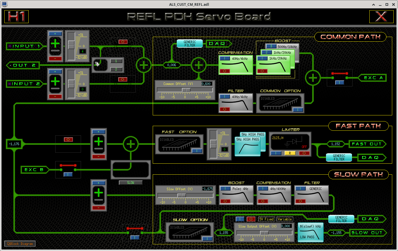
Since I had some time, I quickly measured the OLTF of ALS PDH at X and Y using LSC EXTRA channels I connected some time ago (alog 80826). I enabled the IN2 and made sure that OUT2 is connected to IN1 (1st attachment). With this setting, H1:LSC-[XY]_EXTRA_AI_2/H1:ALS-[XY]_REFL_ERR_OUT_DQ is 40dB smaller than the OLTF, see the circuit diagram of the CM board (D040180 especially page 5) and an overview (D1002416/005).
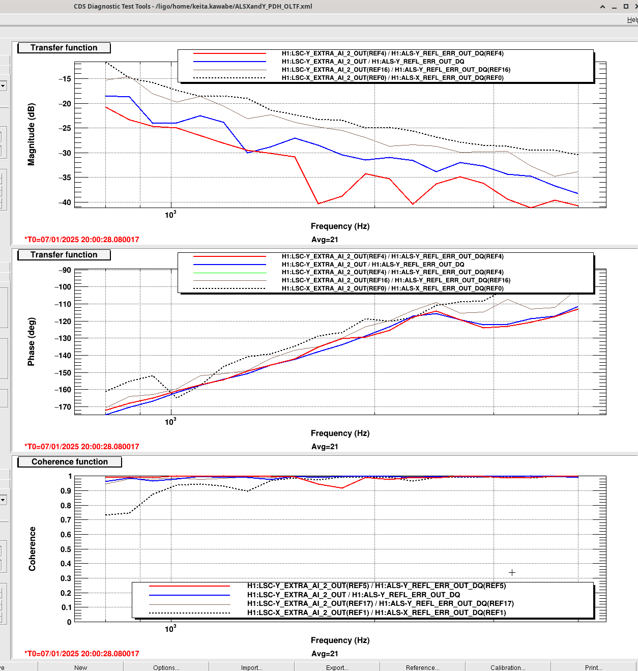
It turns out that the PDH OLTF (2nd attachment, note that there's a factor of 100 in the denominator so you have to add 40dB) is about 10dB smaller in ALSY with the nominal setting (red) than ALSX (black dashed) despite that H1:ALS-Y_REFL_LOCK_LOCKEDGAIN (6dB) is 2dB larger than H1:ALS-X_REFL_LOCK_LOCKEDGAIN (4dB). So there's a total of 12dB gain difference somewhere upstream of the common mode board.
That shouldn't be such a big deal once it's locked, but it could be problematic for acquisition as H1:ALS-Y_REFL_LOCK_ACQUIREGAIN was -20dB while H1:ALS-X_REFL_LOCK_ACQUIREGAIN was and is -6dB. In other words, the electronics gain is 14dB smaller for Y than X and the sensing gain upstream of the common mode board is 12dB smaller for Y. It's 26dB difference in total.
I wanted to adjust the demod phase in Y but was distracted by something else, so I just increased the gain setting for Y: H1:ALS-Y_REFL_LOCK_ACQUIREGAIN is -12 (originally -20), H1:ALS-Y_REFL_LOCK_LOCKEDGAIN is 10 (was 6).
For LOCKEDGAIN, I tried 14dB and it started dropping lock for unknown reasons, 12dB was OK (brown trace) but I just didn't want to get close to 14dB.
I'm pretty sure ACQ gain could be increased further but -12dB is the gain I tested first and it locked quickly, and I didn't have time.
And this is where I was distracted.
I changed the CM board offset while PDH was locked and confirmed that it still has a measurable effect on the green transmission but it's not as drastic as before, this time it's only a few per cent effect. I saw no apparent mode hopping behavior either (i.e. the transmission didn't change shape from 00 to HOM), things were very stable. Not sure if the only difference was the alignment.
As per previous experiences, I went all the way up to -10V (which is attenuated by 0.28/100 in the CM board) but could not get past the true maxima of the transmission (i.e. "the other side of the slope"). Also the IN1 gain seemed to have an effect on the transmission when the offset was constant, i.e. the higher the gain the smaller the transmission.
We know that the error signal (in volts) is not drastically smaller at EY than EX.
After making sure that the demod phase is good, in another maintenance day we could e.g. slightly misalign the arm or TMS and observe the error signal when the arm is free swinging. If this is via HOM, that would make things different, probably for worse.
