FranciscoL, RickS, SivanandaR
In summary:
On Tuesday, March 11, we moved PCALX lower (outer) beam by r = + 2.5 mm, \theta = - 33 deg (from horizontal) on the ETM. We expect to see a large (~20 HOPs) change in \chi_XY.
From our investigations -- an independent method to estimate IFO beam offset using the Pcal -- we believe that the IFO beam offset, when facing the ETM, is (+ 14.3 mm, -- 09.3 mm) in cartesian coordinates. These coordinates yield an angle of arctan(-- 9.3/14.3) ~ -- 33 deg from the horizontal axis of the ETM center.
The first pdf file (polar_out.pdf) plots the IFO beam offset. The black points represent the measurements of a2l (located at '/opt/rtcds/userapps/trunk/isc/common/scripts/decoup/BeamPosition/a2l_lookup.m'). The green points are what is inferred by Pcal measurements. For the Pcal to estimate the IFO beam offset, we use the scalar product of \vec(c) -- the displacement vector of the Pcal center of force for a given actuation, and \vec(b) -- the IFO center of force, as it is derived in T2400032 equation 11. From the plot, there is a clear disagreement on the horizontal component of the IFO beam from both methods. Following equation 11, a measurement in which an actuation from the Pcal beams results in a parallel displecement of the pcal center of force to the real IFO beam center of force should maximize the change \chi_XY. Conversely, an actuation that is perpendicular would not be seen by \chy_XY (no change). The actuation for today was parallel to what the Pcal estimates is the IFO beam position. We plan to make a second actuation, in which we move perpendicular to our estimate of the IFO beam. Ideally, these measurements would increase our confidence of the IFO offset.
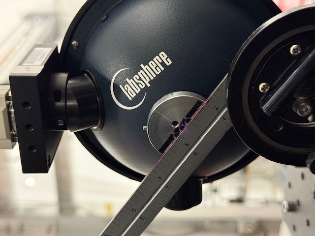
We aligned the target by setting an angle gauge at the calculated 33 deg as seen in the first image (TARGET_ON).
We aligned the Pcal beams to the corresponding apertures by (1) blocking one beam and (2) aligned beam of interest by maximizing the Rx sensor voltage readout from a Keithley digital multimeter (KVM). Since the upper beam has shown inconsistencies in the horizontal displacement (83051), we are actuating on the lower beam. The second image (BOTH_BEAMS) shows both beams after moving the lower beam.
The following table lists the voltage value at each relevant step of the process:
| Step | Comment | Rx Readout [V] |
|---|---|---|
| 1 | Both beams, as found | 2.840 |
| 2 | Upper beam, as found | 1.440 |
| 3 | Upper beam, centered | 1.50 |
| 4 | Lower beam, as found | 1.396 |
| 5 | Lower beam, centered | 1.40 |
| 6 | Lower beam, moved | 1.390 |
Some observations from today's visit to ENDX:
- Clockwise rotation on the yaw actuator moved the lower beam up on the Rx sensor.
- Clockwise rotation on the pitch actuator moved the lower beam to the right on the Rx sensor.
- Noticed an increase in upper (inner) beam after optimizing on center aperture -- so the beams may drift in the order of less than 1 mm on the Rx (roughly half on the ETM) during the span of a week.
- Power imbalance of ~7% of both beams on the center aperture when the target was on.
This is the first of three actuations. Additionally, the data processing still needs about a week of data to diagnose results. We will have nominal results in ~3 weeks.