jeffrey.kissel@LIGO.ORG - posted 12:31, Thursday 20 March 2025 (83468)
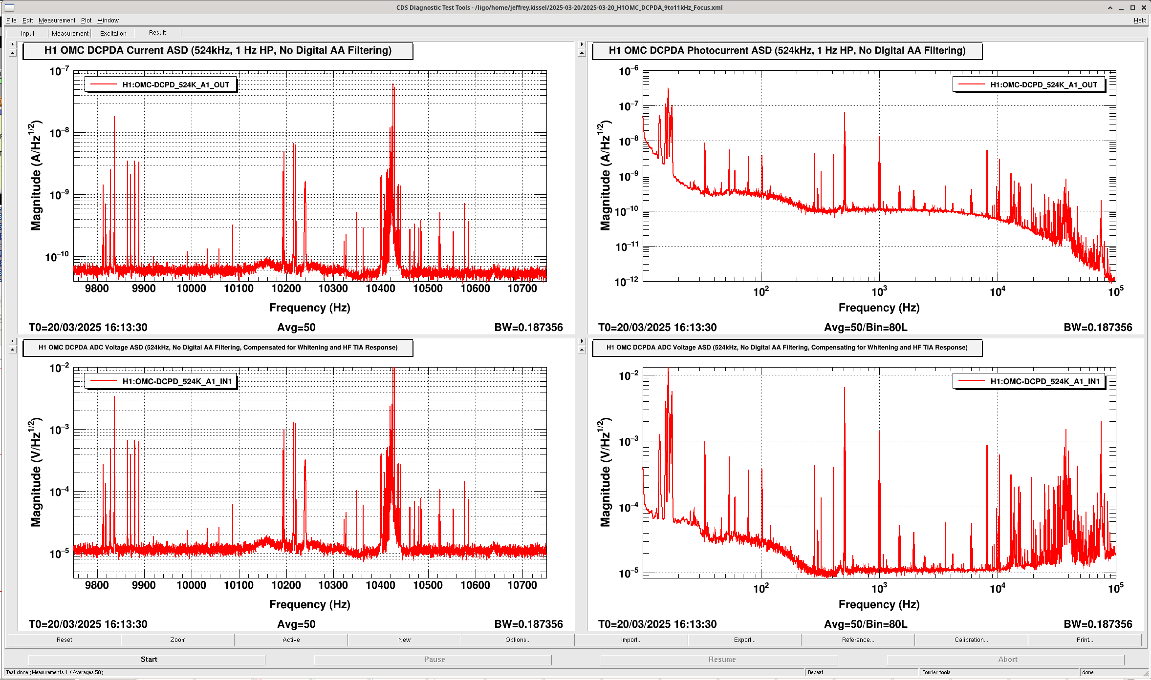
9.75 kHz to 10.75 kHz ASD of OMC DCPD A during Nominal Low Noise, Calibrated in OMC DCPD TEST DAC Drive
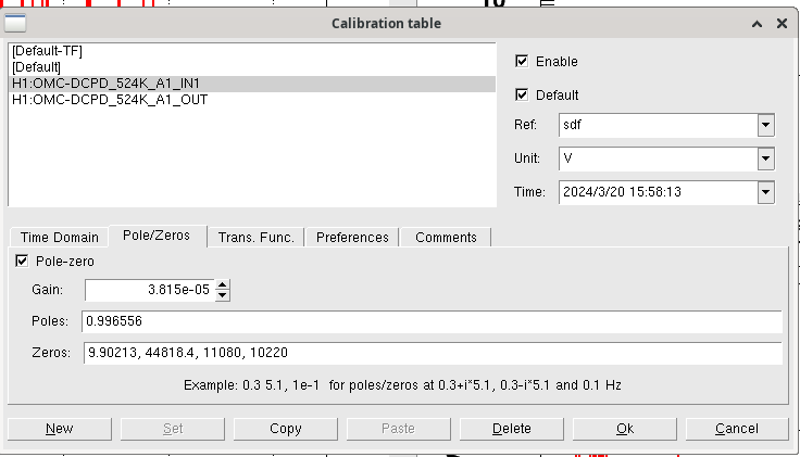
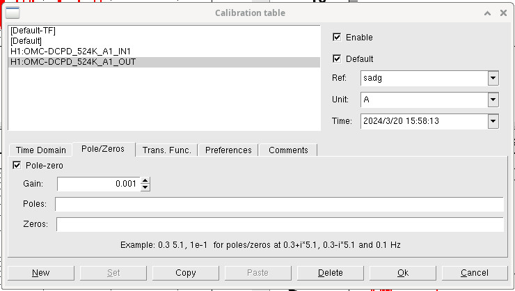
J. Kissel

I've been tasked with using the analog voltage input to the OMC DCPD transimpedance amplifiers (LHO:83466) to drive a sine wave around 10 kHz, in order to try to replicate a recent PI ring up which apparently caused broad-band low frequency noise LHO:83335.

There is a remote excitation channel that typically drives the this analog input excitation path is running at 16 kHz: the H1:OMC-TEST_DCPD_EXC channel's filter module lives in the h1lsc.mdl model in a top_names OMC block at the top level of the model, and the output of that filter bank is connected to the lsc0 IO chassis' DAC_0's 11th / 12th digital/analog channel. That DAC's AI channel goes through quite an adventure before arriving at the OMC whitening chassis input -- following D19000511,
    - AI chassis for lsc0 IO chassis DAC_0 lives in ISC-C1 U7, port OUT8-11 D9M spigot (page 2, component C15), connected to cable ISC_406
    - The long ISC_406 DB9 cable connects to a LEMO Patch Panel (D1201450) on the other end in ISC-R5 U12 (page 22, component C210).
    - Funky LEMO to D9M cable D2200106 ISC_444 connects from the patch panel to the whitening chassis,
    - ISC_444 D9F end of the cable to lands at the  J4 D9M port labeled "From AI/DAC / Test Inputs" of OMC DCPD whitening chassis in U24 of ISC-R5 rack.

... but this won't work: this channel is driven at 16 kHz sampling frequency. So, we can't drive anything technically above 8192 Hz, but realistically above ~5-6 kHz.
I digress.

I'm going with SR785 excitation via DB9 breakout.

Anyways -- I attach here an ASD of the OMC DCPDs sampled at 524 kHz during nominal low noise this morning (taking advantage of the live-only 524 kHz channels), low-passed at 1 Hz, without any digital AA filters; the channel H1:OMC-DCPD_524K_A1 filter banks channels from LHO:82686. The OMC DCPD z:p=1:10 Hz whitening is ON during nominal low noise.

The top panels show a zoomed in, and zoomed out version of the DCPDA ASD calibrated into photocurrent on the PDs (H1:OMC-DCPD_524K_A1_OUT channel, * 0.001 [A/mA], all the rest of the calibration is built in to the front-end filter bank; see OUT DTT Calibration).
The bottom panels show a zoomed in, and zoomed out version of the DCPD ASD calibrated into ADC input voltage, with what whitening that was ON divided out, and the 2x ~11 kHz poles of the TIA divided out. (H1:OMC-DCPD-524K_A1_IN channel, * 1/4 [four-channel copy sum to avg conversion] * 0.0001526 [V/ct for 40 Vpp range over an 18 bit ADC] * z:p = (10):(1) inverse whitening filter * z:p = (11k,10k):([]) inverse HF TIA response )

In the zoomed in version of the plots, you can clearly see the mess of acoustic modes at 10.4 kHz.
One can also see relatively noise free region at 10.3 kHz that looks clean enough for me to target with my analog excitation.

I plot the de-whitened ADC voltage because the transfer function between the TEST DAC input and the TIA's output voltage is designed to the 1.0 in the GW band, from ~50 to 5 kHz, given that in that band, the transimpedance is 100e3 [V/A] and the series resistor that turns the voltage injection of the TEST input into current is 100e3 [V/A] (see ). So "nominally" un-whitened ADC counts should be a one-to-one map to DAC voltage input. At 10 kHz, however, the 2x ~11 kHz poles of the TIA, which drop the TEST input voltage by a factor of 5x at 10 kHz (see, e.g. plots from LHO:78372)

So, that's why in the lower panels of the above mentioned plot of OMC DCPD A's ADC voltage calibrated in the way mentioned above. This should be a one-to-one map to the equivalent DAC voltage to drive.

I looks like the non-rung-up 10.4 kHz PI modes today were of-order 1e-2 V = 10 mV, and the surrounding noise floor is around 1e-5 V = 10uV = 0.01 mV of equivalent DAC drive.

The lower limit of the SR785 SRC amplitude is 0.1 mVp = 0.2 mVpp (single ended).
Also, using the SR785 in a FFT measurement mode, where you can drive the source at a single frequency, there is no ramp. It's just ON and/or OFF.
(I should also say that a SR DS340 function generator also doesn't have a ramp on its output. I considered using that too.)

So -- hopefully, suddenly turning on a noisy 10.3 kHz line at 0.1 mVp into the IFO with a noise floor of 0.01 mV/rtHz at 10kHz won't cause problems, but ... I'm nervous.
Images attached to this report