Mayank, Jennie, Siva, Keita
Continuing measurements carried out on the ISS arrray in alog 83077 (between that alog and today Siva and Mayank had set up measurements of the first four ISS array PDs with oscilloscopes).
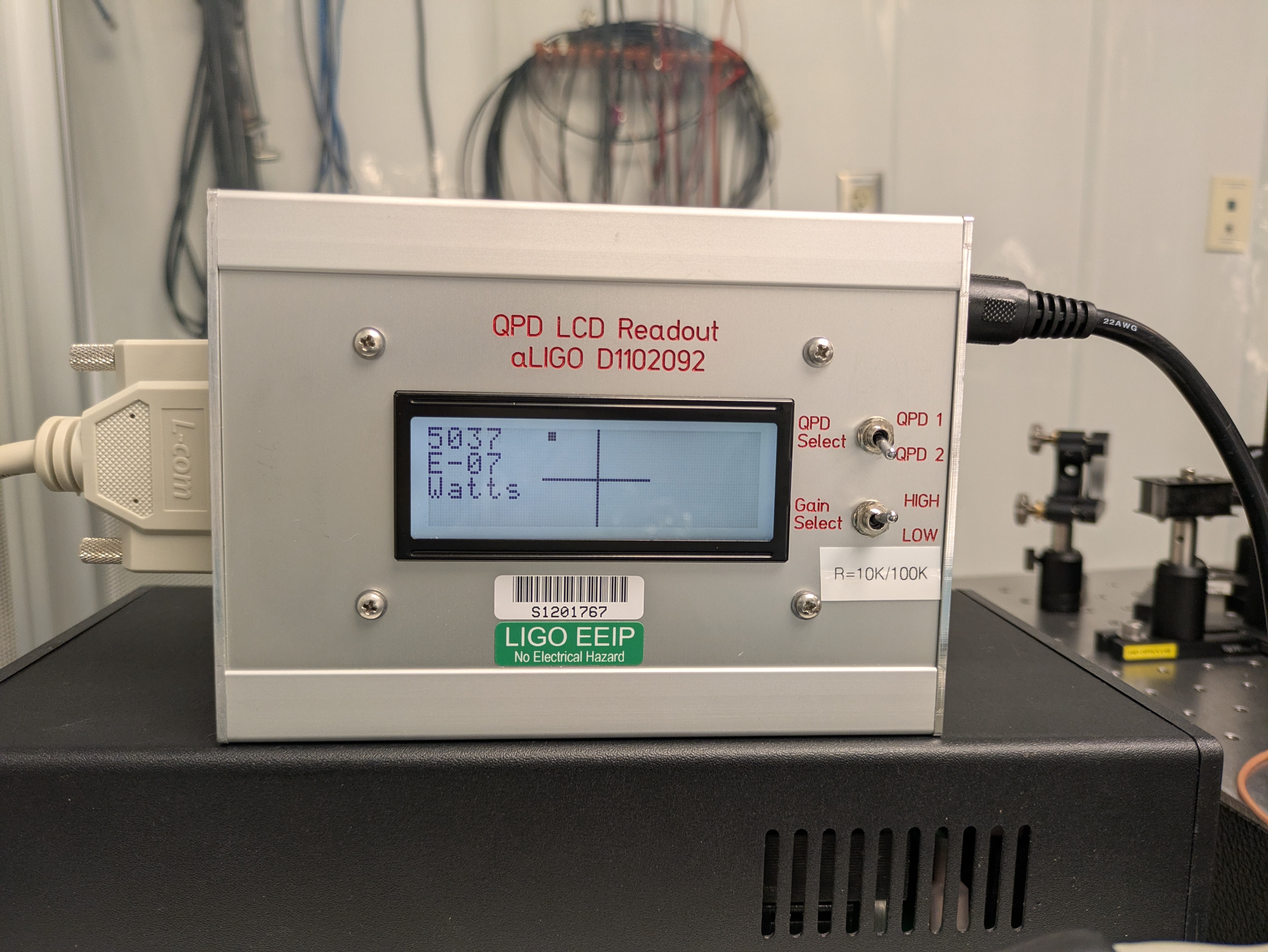
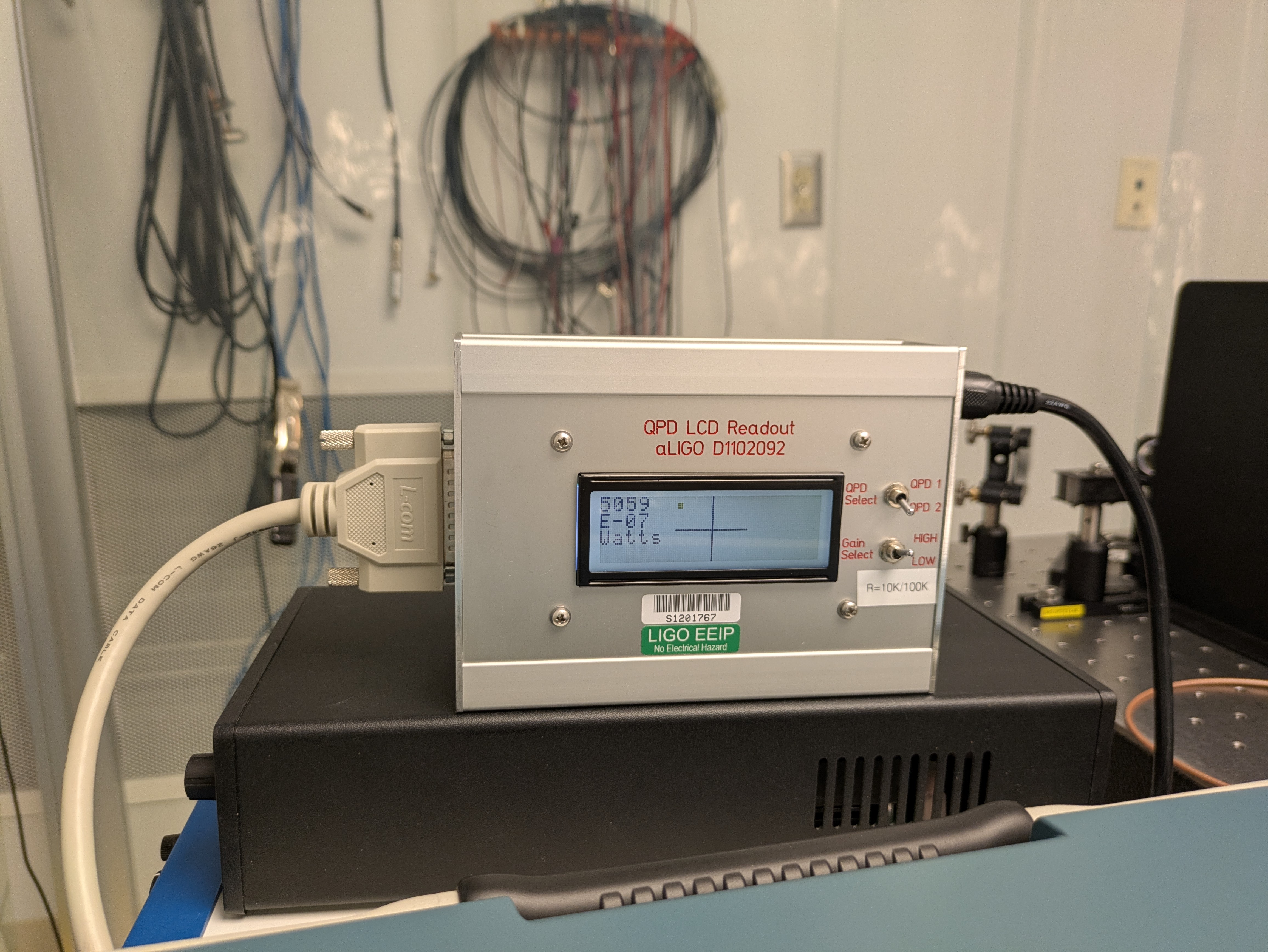
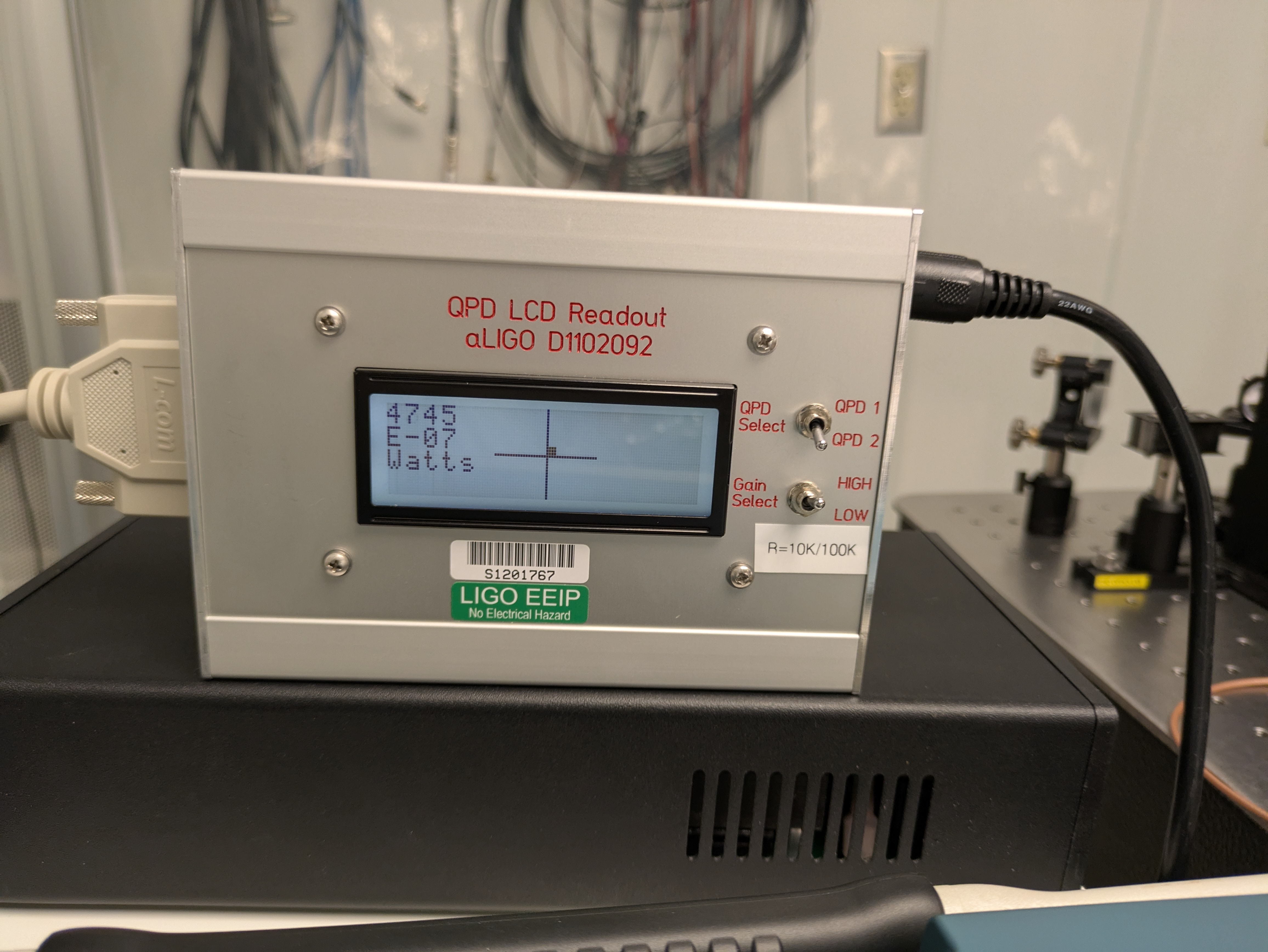
One problem emerging was that the QPD (shown in this image) readout doers not give a number for how far from centre the QPD is in our lab setup (it uses an old LCD output box with a microcontroller we can't find the documentation for). Another is that the four PDs are best aligned away from the centre of the QPD. So after testing it may be neccessary to move the QPD for best alignment.
This morning Siva and Mayank setup the readout for all 8 PDs and also added a polarising beamsplitter between the PZT controlled mirror used for dithering the alignment to the array, and the aperture on the array assembly input. This was to ensure the polarisation was not affecting the measurement.
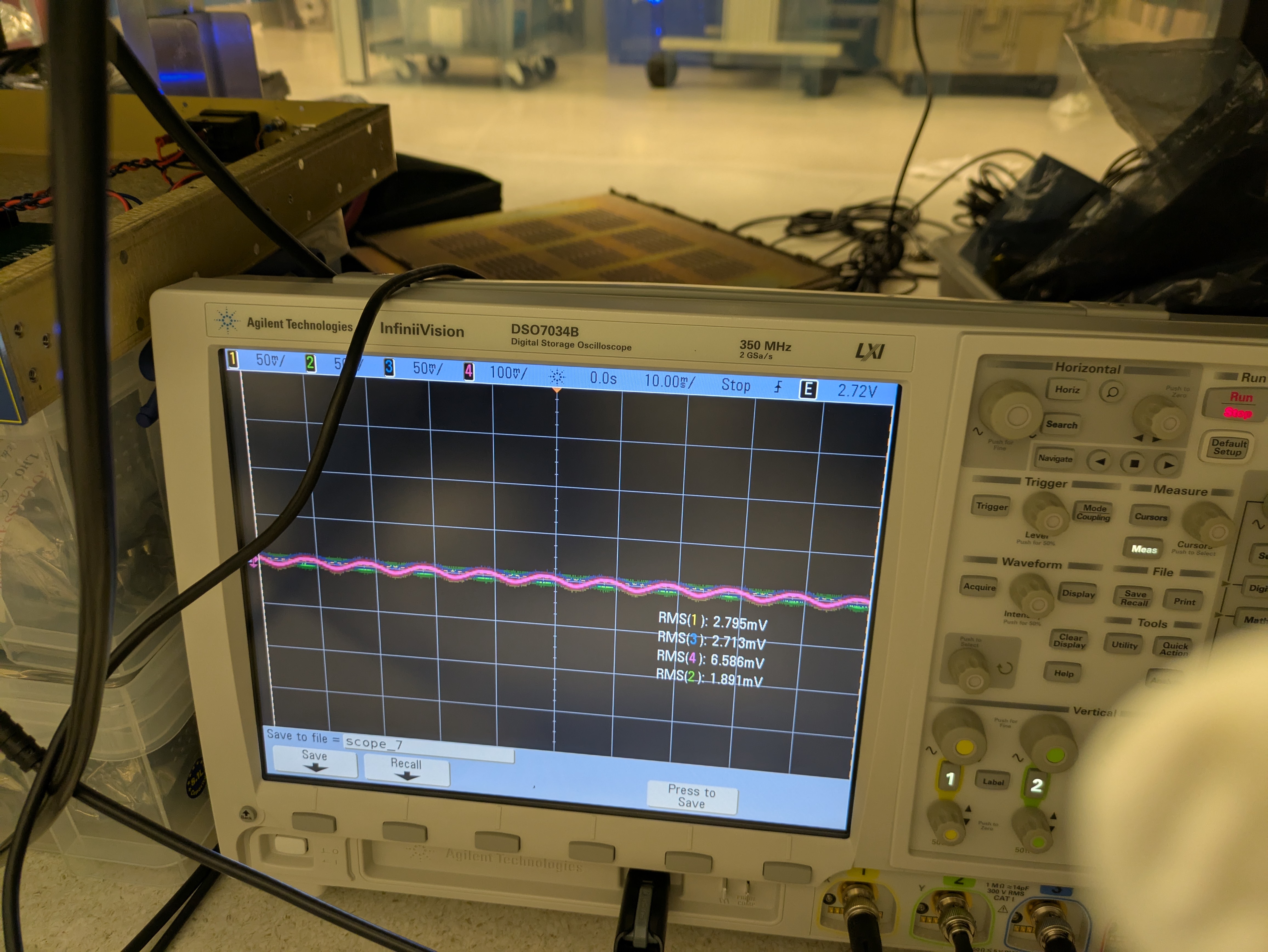
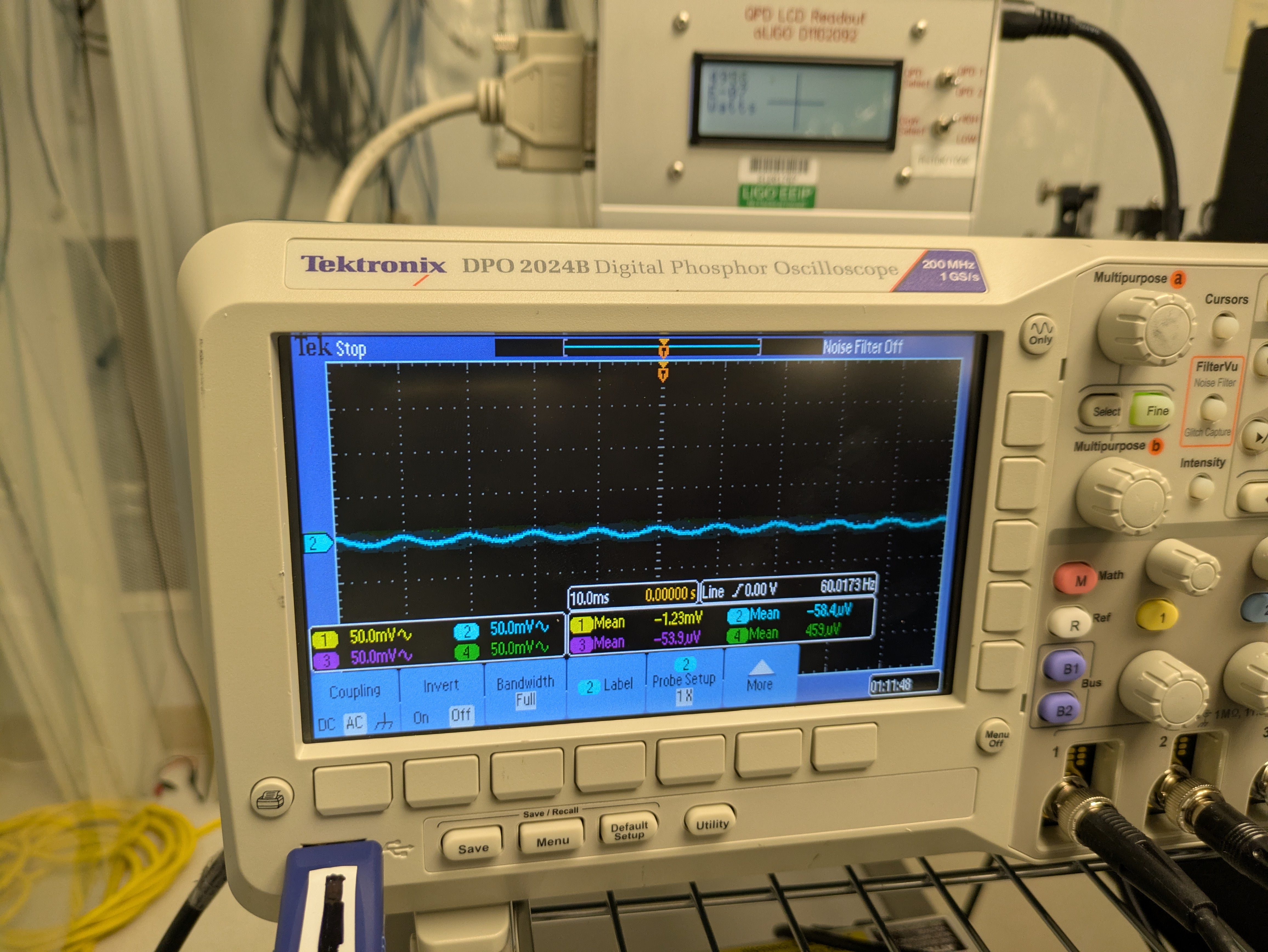
Mayank and I measured the AC and DC signals for all 8 PDs using a horizontal dither on the PZT controlled mirror before the polarising beamsplitter, when:
1: the light was centered on the QPD and
2: when it was in the observed 'best alignment' when the coupling from the dither to the PDs was mininimised.
Changing the DC alignment is done with the pitch and yaw screws on the PZT mirror mount.
After the first couple of measurements we tried to get a time when the laser was not in a noisy state this could be because it keeps running multi-mode or some pickup in the measurement cables - not sure so further investigation needed.
It does seem possible to obtain a spot where all the 8 PDs are minimised in the top left-hand quadrant of the QPD for.
We also repeated measurements 1 and 2 with a vertical dither on the PZT. This is the LCD screen when aligned at its best alignment on the PDs for vertical dither on the PZT mirror. This is the readout for PDs 1-4 and 5-8 at this position. This is the LCD screen when the input alignment is such that the QPD is centred.
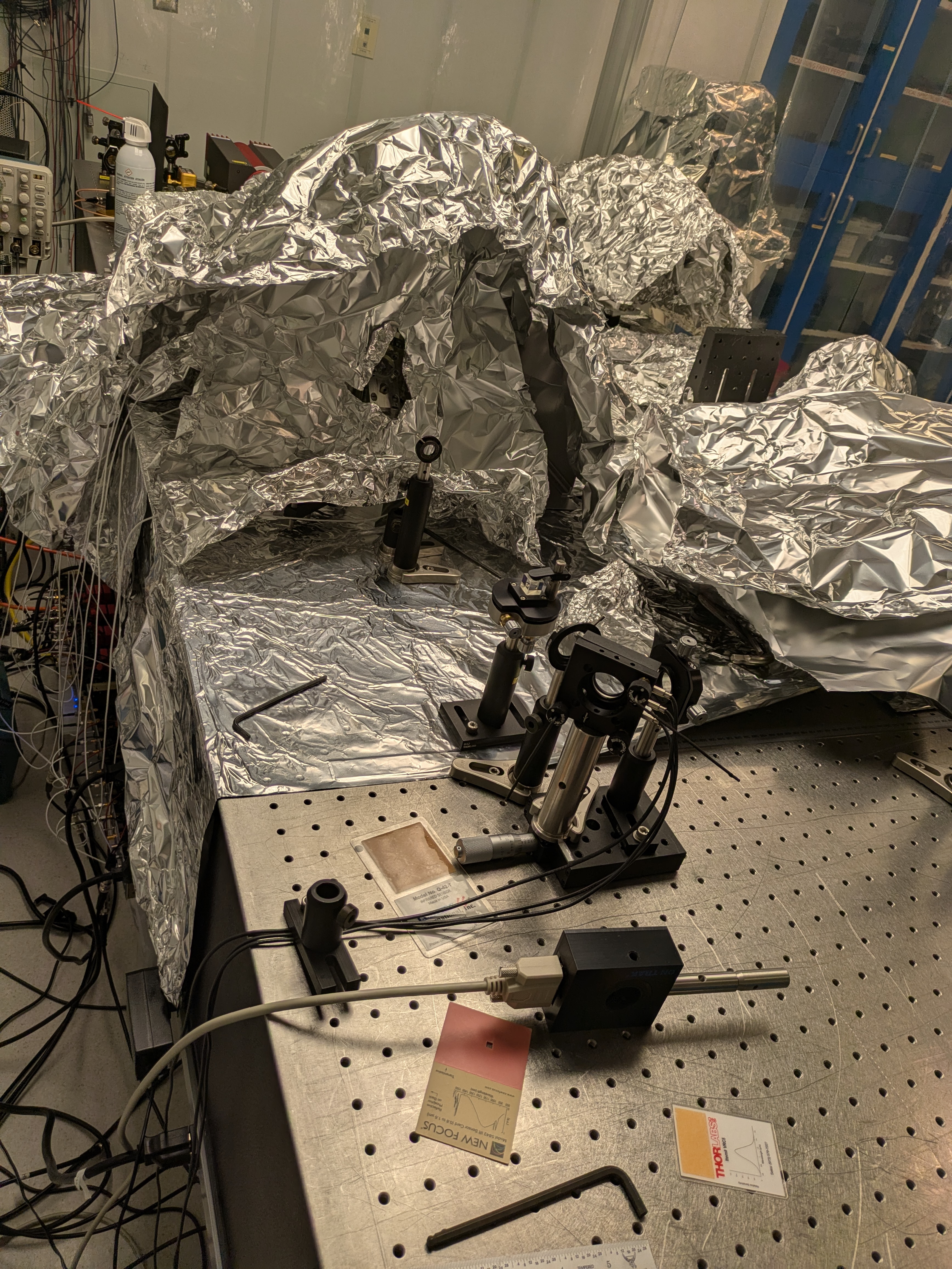
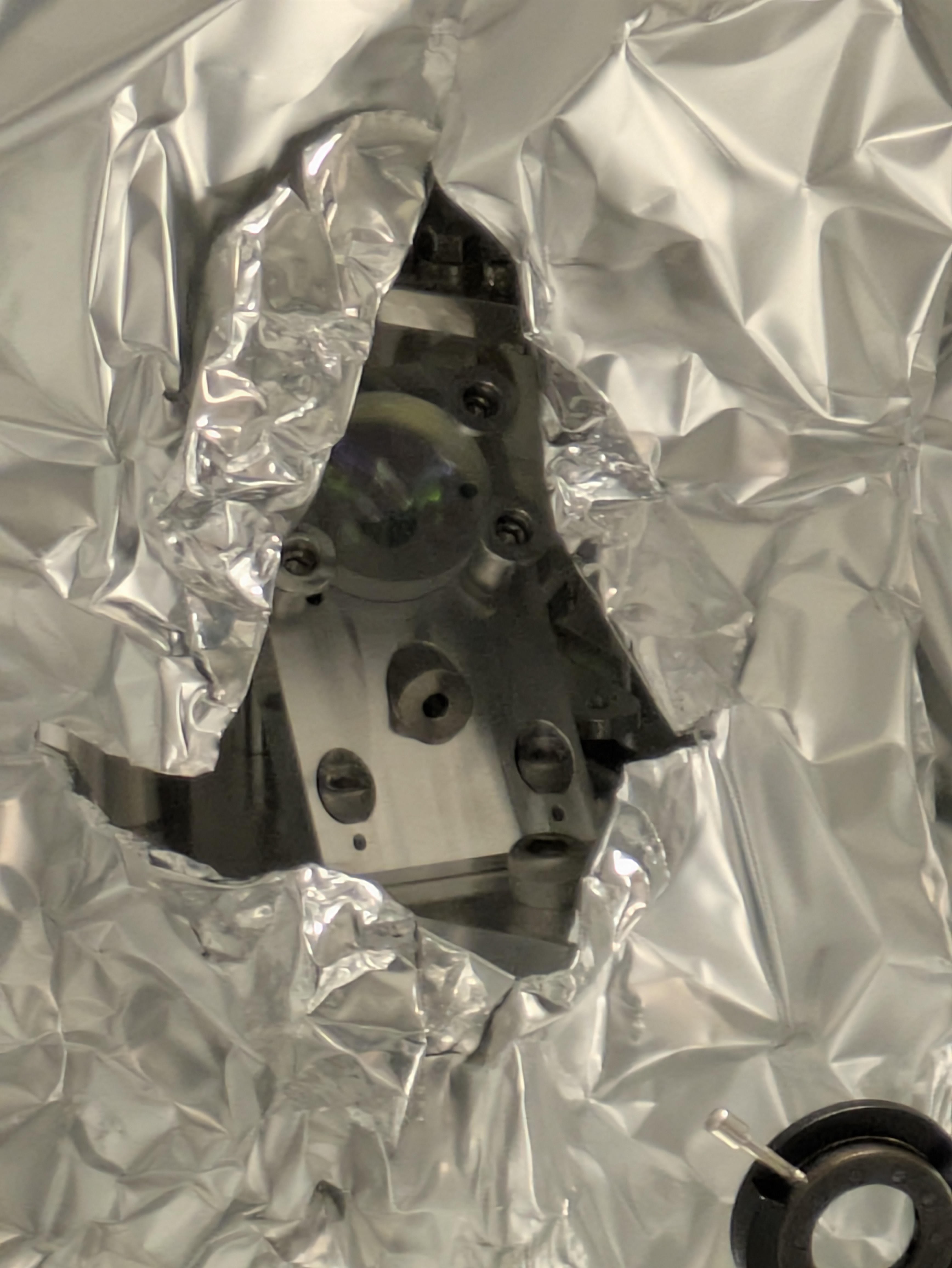
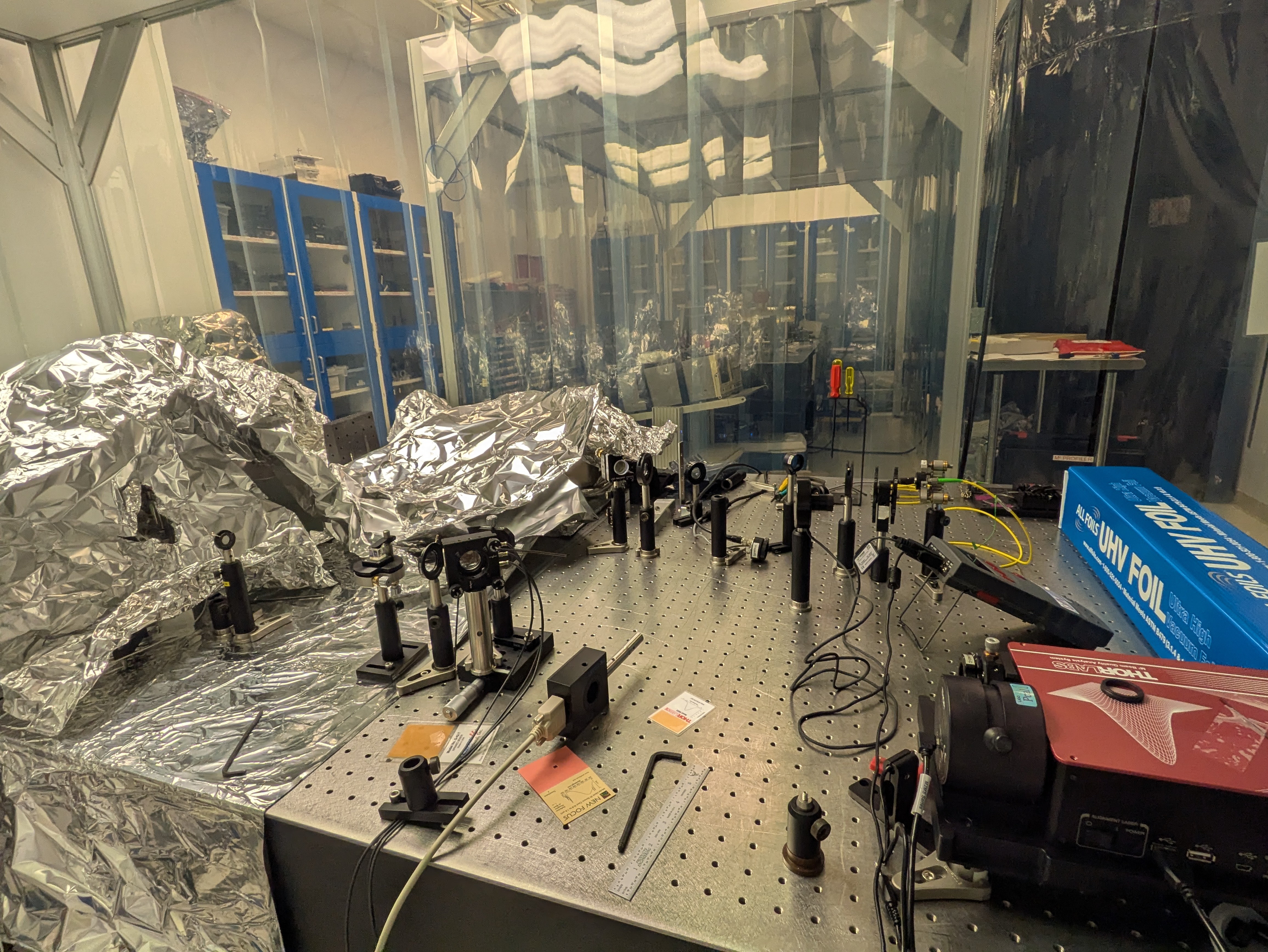
I have attached our data file references for the measurements and some photos.
Keita also tuned the laser temperature control thermistor from a resistance of 10 kOhms to 9.602 kOhms which seems to stop the laser mode-hopping and becoming noisy. Siva has also hooked up a cable between the QPD and a different QPD readout box which we can get oscilloscope readouts from. More measurements to follow...