Reports until 15:03, Monday 07 April 2025
H1 SUS (CDS, SYS)
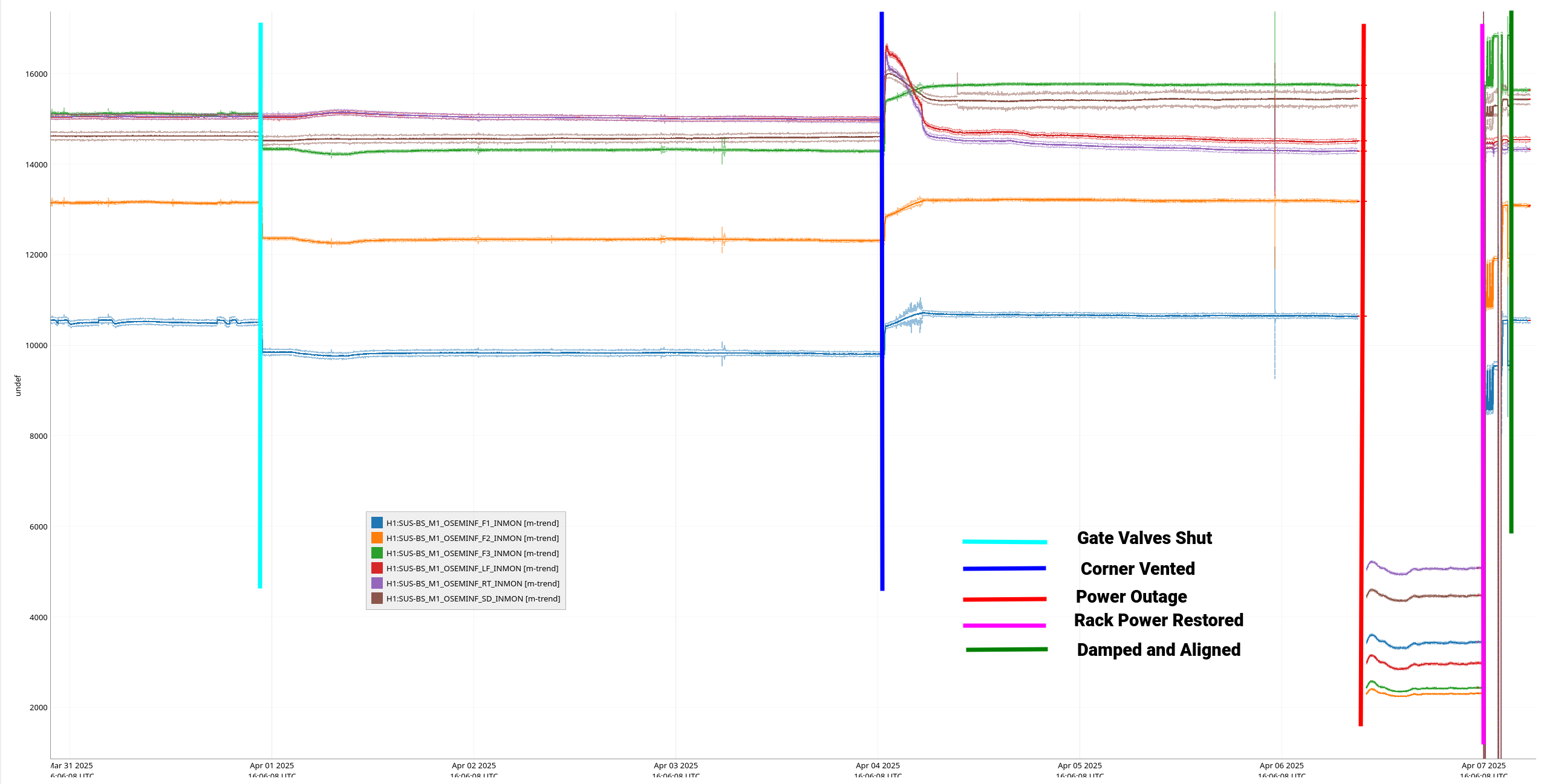
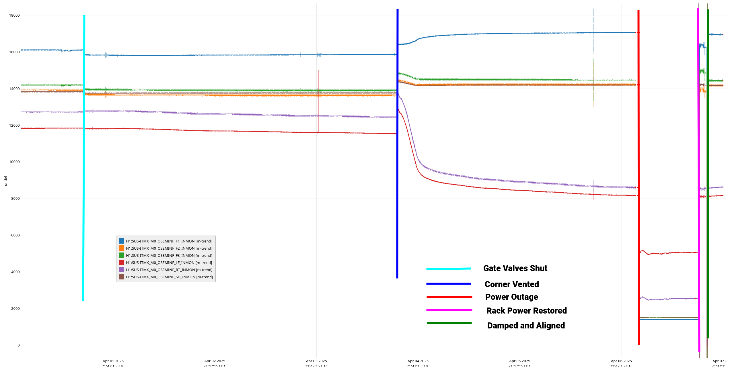
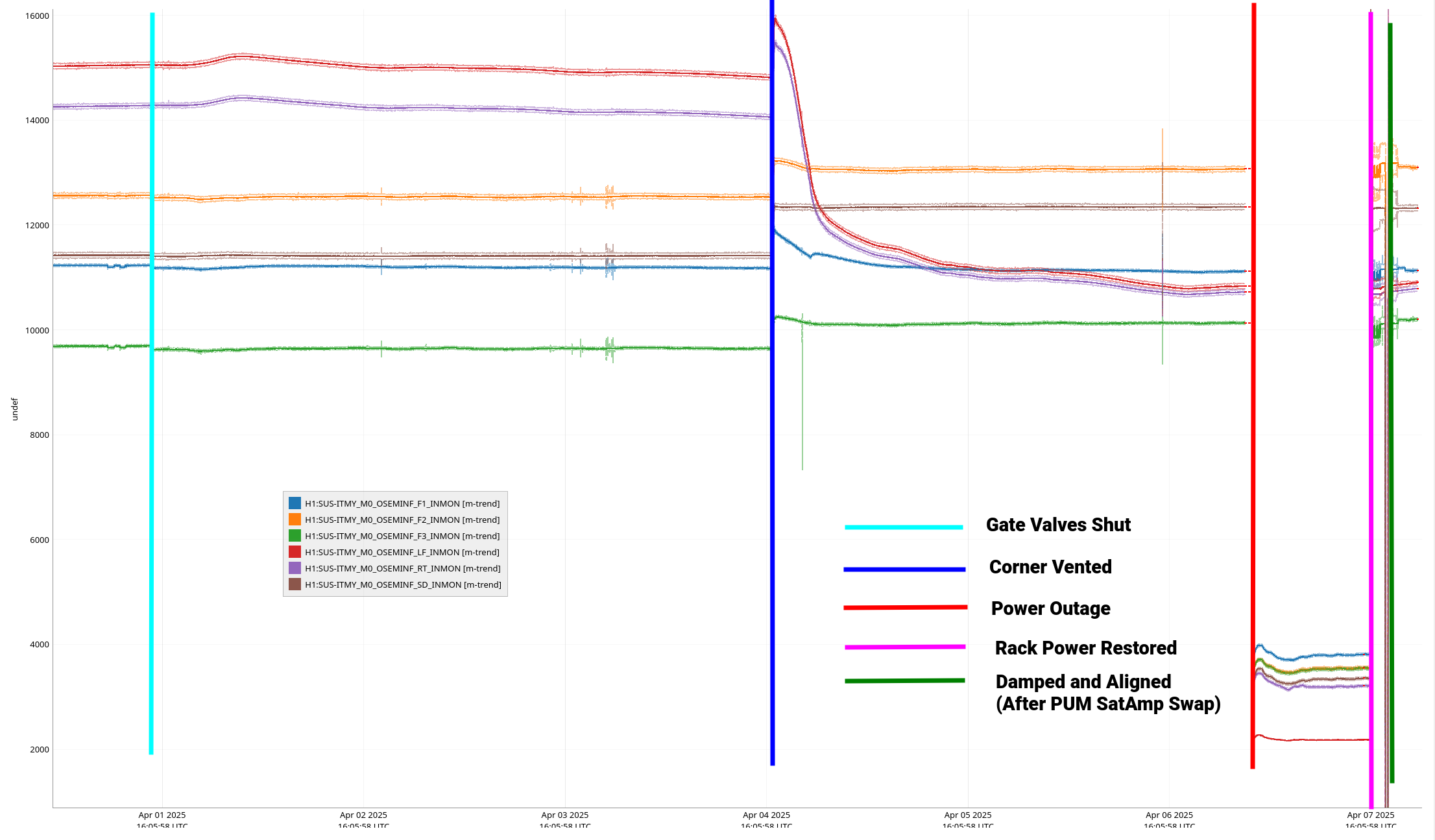
jeffrey.kissel@LIGO.ORG - posted 15:03, Monday 07 April 2025 - last comment - 13:20, Tuesday 08 April 2025(83787)
Recovery from 2025-04-06 Power Outage: +18V DC Power Supply to SUS-C5 ITMY/ITMX/BS Rack Trips, ITMY PUM OSEM SatAmp Fails; Replaced Both +/-18 V Power Supplies and Replaced ITMY PUM OSEM SatAmp
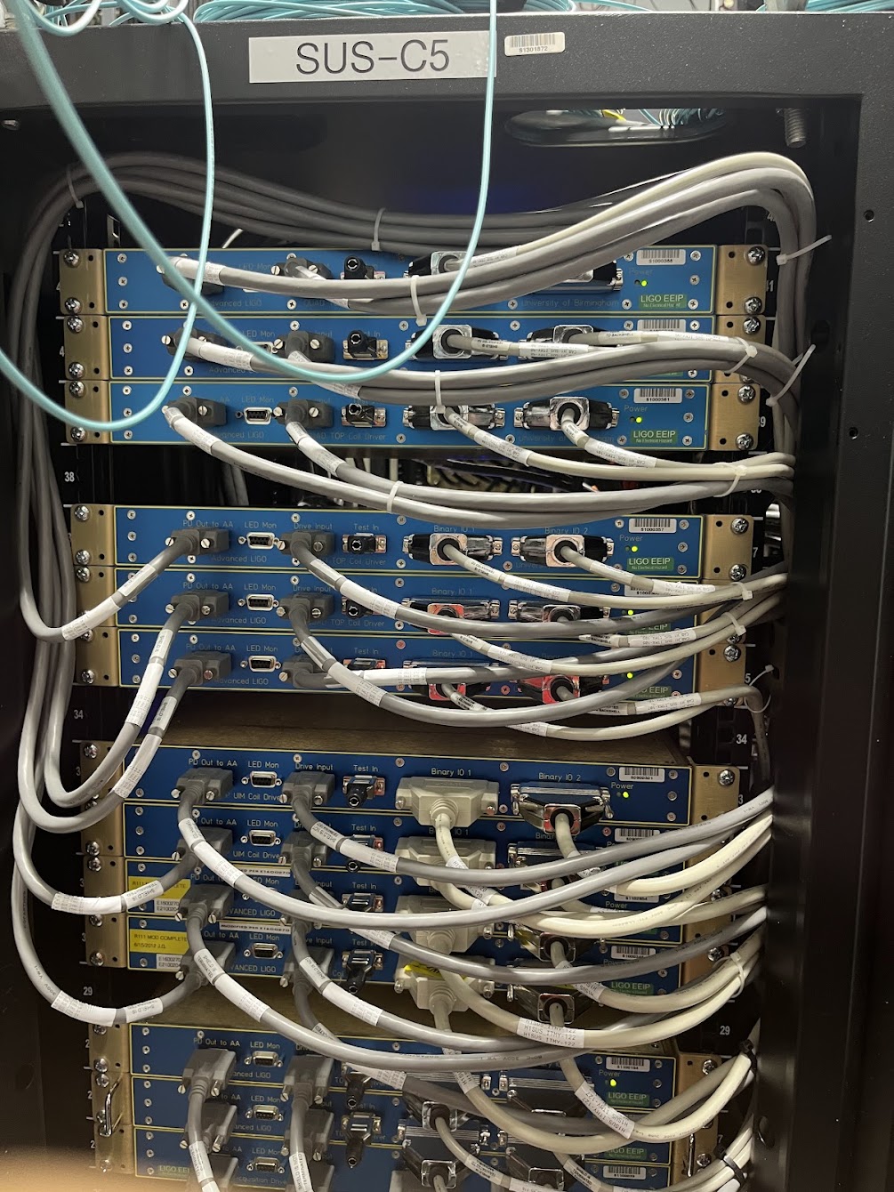
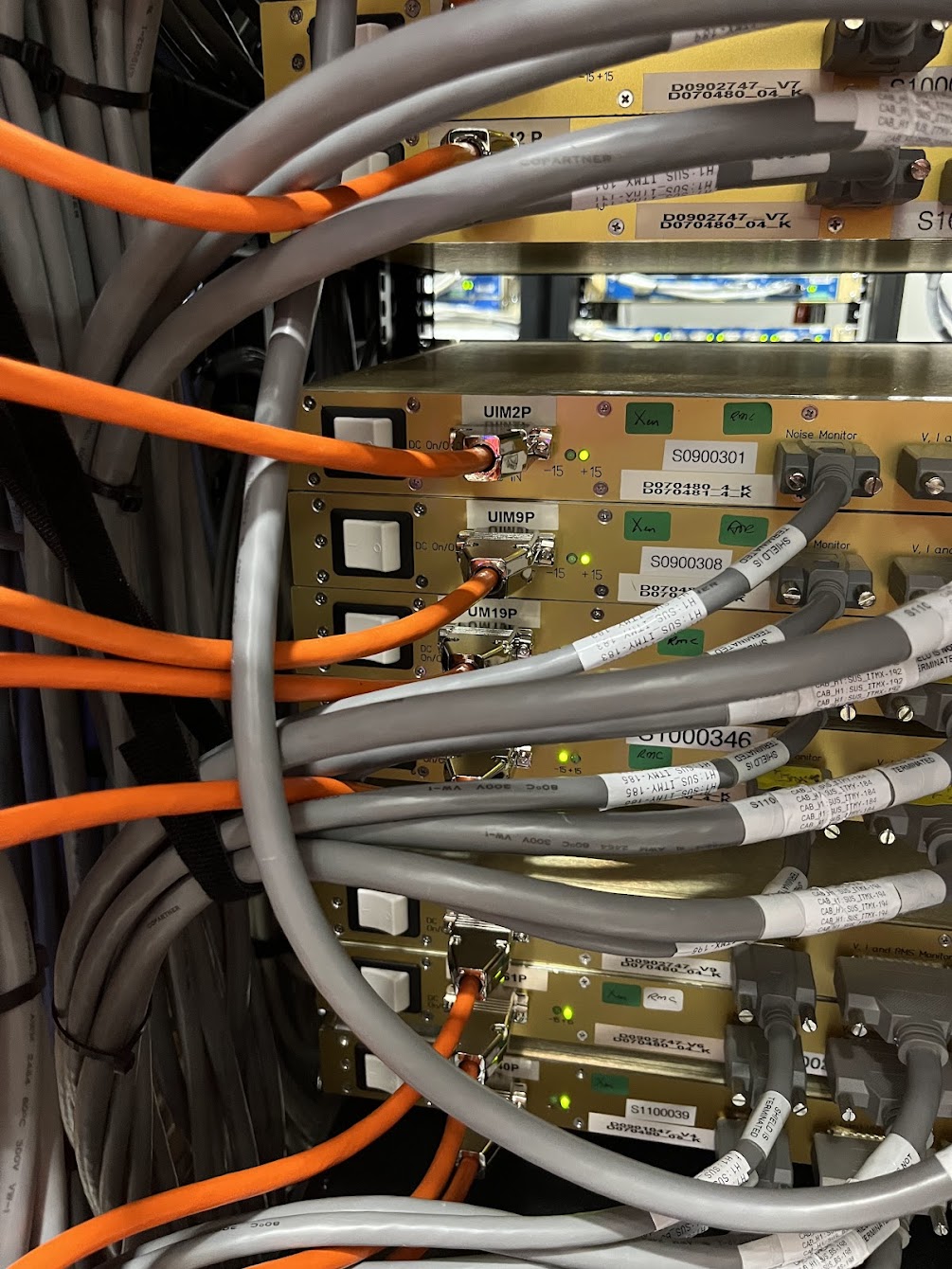
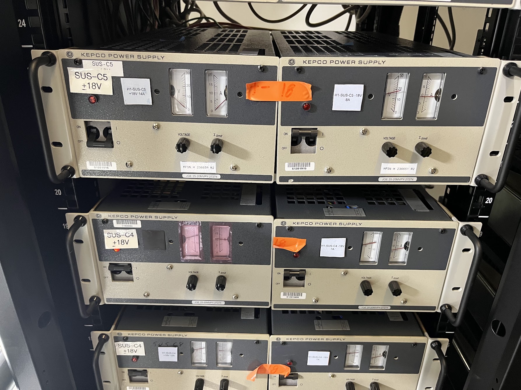
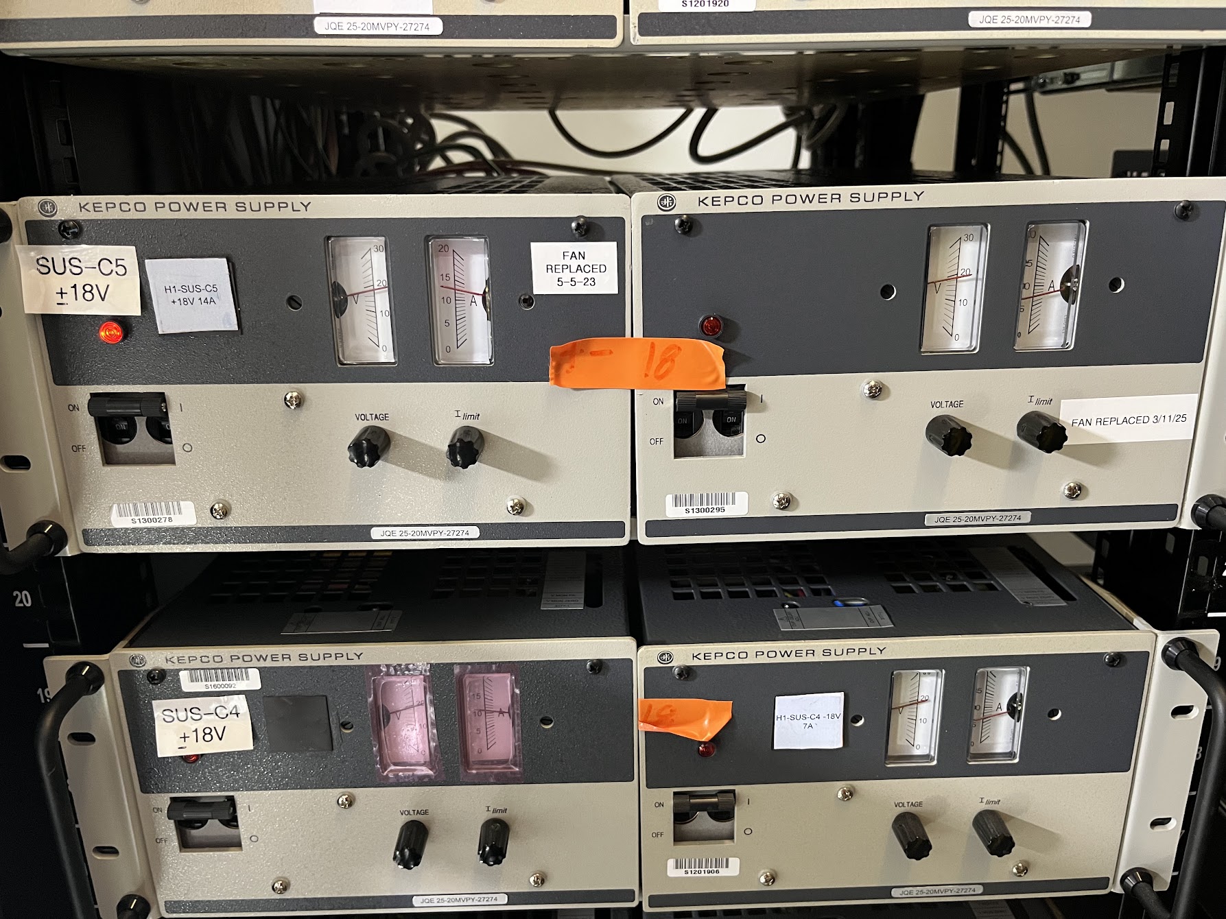
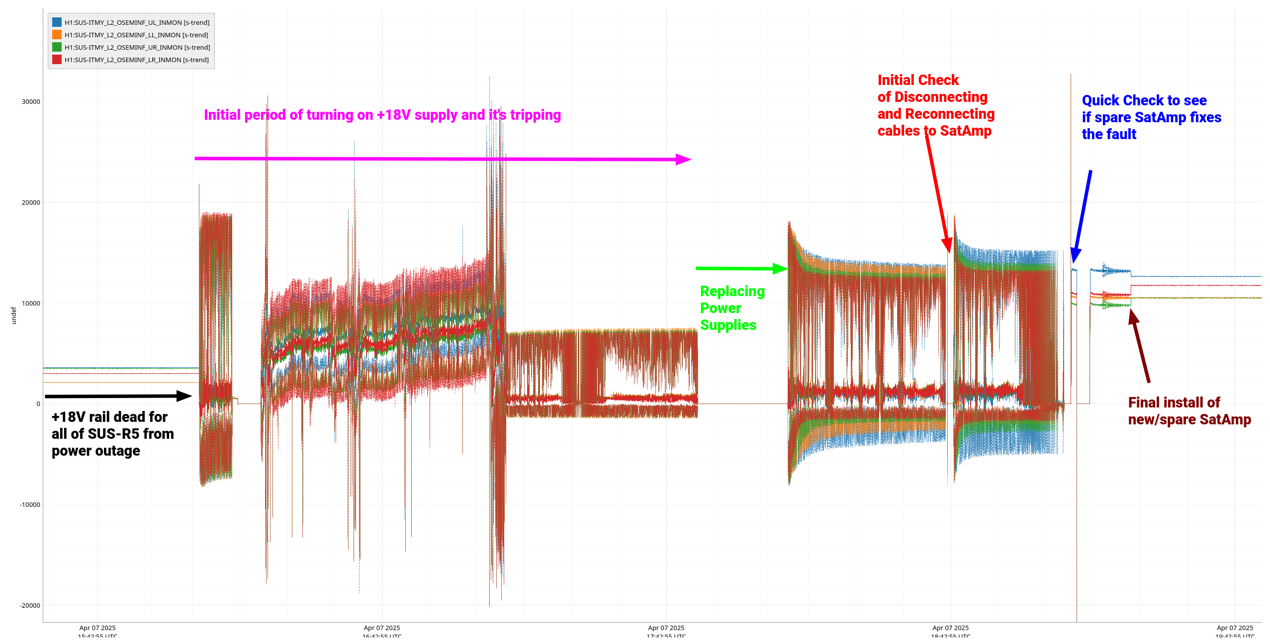
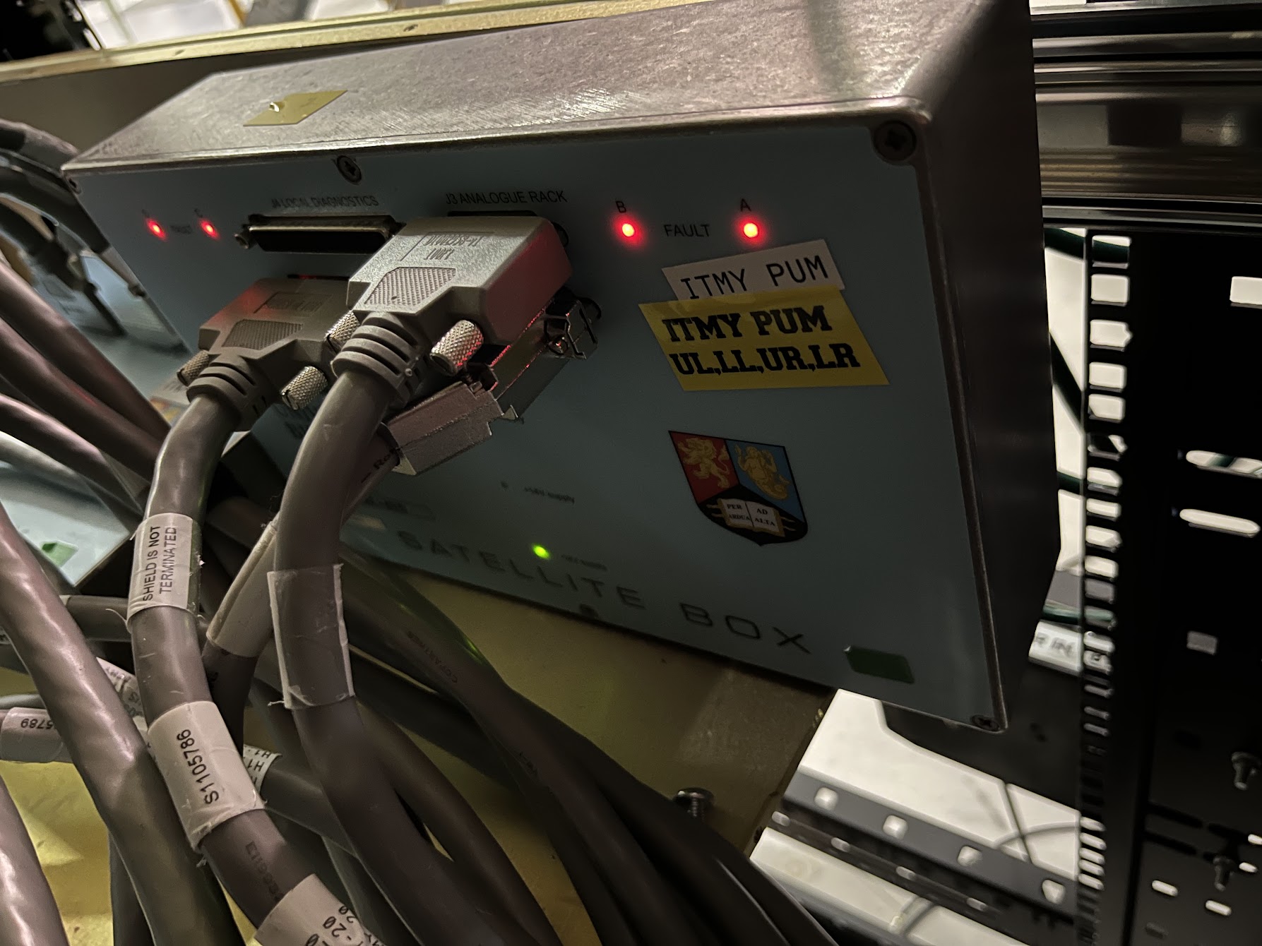
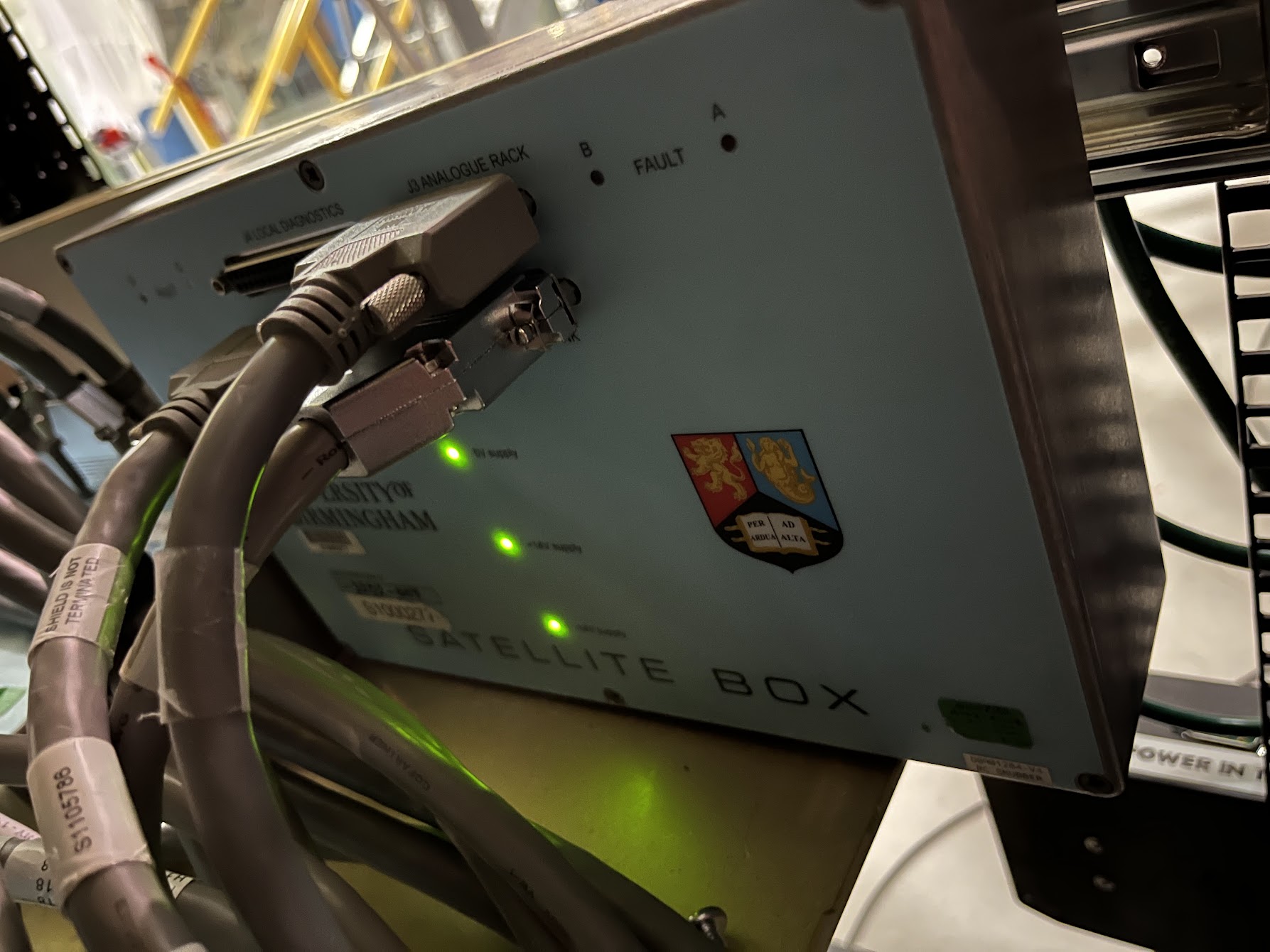
J. Kissel, R. McCarthy, M. Pirello, O. Patane, D. Barker, B. Weaver
2025-04-06 Power outage: LHO:83753

Among the things that did not recover nicely from the 2025-04-06 power outage was the +18V DC power supply to the SUS ITMY / ITMX / BS rack, SUS-C5. The power supply lives in VDC-C1 U23-U21 (Left-Hand Side if staring at the rack from the front); see D2300167. More details to come, but we replaced both +/-18V power supplies and SUS ITMY PUM OSEMs satamp did not survive the powerup, so we replaced that too.

Took out 
    +18V Power Supply S1300278
    -18V Power Supply S1300295
    ITMY PUM SatAmp S1100122

Replaced with
    +18V Power Supply S1201919
    -18V Power Supply S1201915
    ITMY PUM SatAmp S1000227
Comments related to this report
jeffrey.kissel@LIGO.ORG - 13:20, Tuesday 08 April 2025 (83810)CDS, SUS
And now... the rest of the story.

Upon recovery of the suspensions yesterday, we noticed that all the top-mass OSEM sensor values for ITMX, ITMY, and BS were low, *all* scattered from +2000 to +6000 [cts]. They typically should be typically sitting at ~half the ADC range, or ~15000 [cts]; see ~5 day trend of the top mass (main chain, M0) OSEMs for H1SUSBS M1,ITMX M0, and H1SUSITMY M0. The trends are labeled with all that has happen in the past 5 days. The corner was vented on Apr 4 / Friday, so that changes the physical position of the suspensions and the OSEMs see it. At the power outage on Apr 6, you can see a much different, much more drastic change. 

Investigations are rapid fire during these power outages, with ideas and guesses for what's wrong are flying everywhere. The one that ended up having fruit was that Dave mentioned that it looked like "they've lost a [+/-18V differential voltage] rail or something," -- where he's thinking about the old 2011 problem LLO:1857 where 
   - There's a SCSI cable that connects the SCSI ports of a given AA chassis to the SCSI port of the corresponding ADC adapter card on the back of any IO chassis
   - The ADC Adapter Card 's port has very small, male pins that can be easy bent if one's not careful during the connection of the cable.
   - Sometimes, these male pins get bent in such a way that the (rather sharp) pin stabs into the plastic of the connecter, rather than into the conductive socket of the cable. Thus, (typically) one leg, of one differential channel is floating, and this manifests digitally in that it creates an *exact*  -4300 ct (negative 4300 ct) offset that is stable and not noisy. 
   - (as a side note, this issue was insidious: once one bent male pin on the ADC adapter card was bent, and mashed into the SCSI cable, that *SCSI* cable was now molded to the *bent* pin, and plugging it in to *other* adapter cards would bend previously unbent pins, *propagating* the problem.) 

Obviously this wasn't happening to *all* the OSEMs on three suspensions without anyone touching any cables, but it gave us enough clue to go out to the racks.
Another major clue -- the signal processing electronics for ITMX, ITMY and BS are all in the same rack -- SUS-C5 in the CER.
Upon visiting the racks, we found, indeed, that all the chassis in SUS-C5 -- the coil drivers, TOP (D1001782), UIM (D0902668) and PUM (D0902668) -- had their "-15 V" power supply indicator light OFF; see FRONT and BACK pictures of SUS-C5.

Remember several quirks of the system that help us realize what's happened (and looking at the last page of ITM/BS wiring diagram, D1100022 as your visual aide):
(1) For aLIGO "UK" suspensions -- the OSEM *sensors'* PD satellite amplifiers (sat amps, located out in the LVEA within the biergarten) that live out in the LVEA field racks are powered by the coil drivers to which their OSEM *coil actuators* are connected.
So, when the SUS-C5 coil drivers lost a differential power rail, that makes both the coils and the sensors of the OSEM behave strangely (as typical with LIGO differential electronics: not "completely off" just "what the heck is that?"). 
(2) Just as an extra fun gotcha, all of the UK coil drivers back panels are *labeled incorrectly* so that the +15V supply voltage indicator LED is labeled "-15" and the -15V supply is labeled "+15".
So, this is why the obviously positive 18V coming from the rack's power rail is off, but the "+15" indicator light is on an happy.  #facepalm
(3) The AA Chassis and Binary IO for these SUS live in the adjacent SUS-C6 rack; it's + and - 18V DC power supply (separate and different from the supplies for the SUS-C5 rack) came up fine without any over-current trip. Similarly the IO chassis, which *do* live in SUS-C5, are powered by a separate single-leg +24V from another DC power supply, also coming up fine without over-current trip.
So, we had a totally normal digital readback of the odd electronics behavior.
(4) Also note, at this point, we had not yet untripped the Independent Software Watch Dog, and the QUAD's Hardware Watchdog had completely tripped. 
So, if you "turn on the damping loops" it looks like nothing's wrong; at first glance, it might *look* like there's drive going out to the suspensions because you see live and moving MASTER_OUT channels and USER MODEL DAC output, missing that there's no IOP MODEL DAC output. and it might *look* like the suspensions are moving as a result because there are some non-zero signals coming into on OSEMINF banks and they're moving around, so that means the damping loops are doing what they do and blindly taking this sensor signal, filtering it per normal, and sending a control signal out.

Oi.

So, anyways, back to the racks -- while *I* got distracted inventorying *all* the racks to see what else failed, and mapping all the blinking lights in *all* the DC power supplies (which, I learned, are a red herring) -- Richard flipped on the +18V power supply in VDC-C1 U23, identifying quickly that it had over-current-tripped when the site regained power.
See the "before" picture of VDC-C1 U23 what it looks like tripped -- the "left" (in this "front of the rack" view) power supply's power switch on the lower left is in the OFF position, and voltage and current read zero.

Turning the +18V power supply on *briefly* restored *all* OSEM readbacks, for a few minutes.
And then the same supply, VDC-C1 U23, over-current tripped again. 
So Richard and I turned off all the coil drivers in SUS-R5 via their rocker switches, turned on the VDC-C1 U23 left +18V power supply again, then one-by-one powered on the coil drivers in SUS-C5 with Richard watching the current draw on the VDC-C1 U23 power supply.

Interesting for later: when we turned on the ITMY PUM driver, he shouted down "whup! Saw that one!"
With this slow turn on, the power supply did not trip and power to the SUS-R5 held, so we left it ...for a while.
Richard and I identified that this rack's +18V and -18V power supplies had *not* yet had their fans upgraded per IIET:33728.
Given that it was functioning again and having other fish to fry, we elected to not *yet* to replace the power supplies.

Then ~10-15 minutes later, the same supply, VDC-C1 U23, over-current tripped again, again . 
So, Marc and I went forward with replacing the power supplies.
Before replacement, with the power to all the SUS-C5 rack's coil drivers off again, we measured the output voltage of both supplies via DVM: +19.35 and -18.7 [V_DC].
Then we turned off both former power supplies and swapped in the replacements (see serial numbers quoted in the main aLOG); see "after" picture.

Not knowing better we set the supplies to output to a symmetric +/-18.71 [V_DC] as measured by DVM. 
Upon initial power turn on with no SUS-R5 coil drivers on, we measured the voltage from an unused 3W3 power spigot of the SUS-R5 +/-18 V power rail, and measured a balanced +/-18.6 [V_DC].
Similar to Richard and I earlier, I individually turned on each coil driver at SUS-C5 while Marc watched the current draw at the VDC-C1 rack.
Again, once we got the ITMY PUM driver we saw a large jump in current draw. (this is one of the "important later")
I remeasured the SUS-R5 power rail, and the voltage on positive leg had dropped to +18.06 [V_DC].
So, we slowly increased the requested voltage from the power supply to achieve +18.5 [V_DC] again at the SUS-R5 power rail. 
This required 19.34 [V_DC] at the power supply.
Welp -- I guess whomever had set the +18V power supply to +19.35 [V_DC] some time in the past had come across this issue before.

Finishing up at the supplies, we restored power / turned to all the remaining coil drivers had watched it for another bit. 
No more over-current trips. 
GOOD! 

... but we're not done!

... upon returning to the ITMY MEDM overview screen on a CDS laptop still standing by the rack, we saw the "ROCKER SWITCH DEATH" or "COIL DRIVER DEATH" warning lights randomly and quickly flashing around *both* the L1 UIM and the L2 PUM COILOUTFs. Oli reported the same thing from the control room. However, both those coil drivers power rail lights looked fine and the rocker switches had not tripped. Reminding myself that these indicator lights are actually watching the OSEM sensor readbacks; if the sensors are some small threshold around zero, then the warning light flashes. This was a crude remote indicator of whether the coil driver itself had over-current tripped because again, the sensors are powered by the coil driver, so if the sensors are zero then there's a good chance the coil driver if off.
But in this case we're staring at the coil driver and it reports good health and no rocker switch over-current trip.
However we see the L2 PUM OSEMs were rapidly glitching between "normal signal" of ~15000 [cts] and a "noisy zero" around 0 [ct] -- hence the red, erratic (and red herring) warning lights.

Richard's instincts were "maybe the sat amp has gone in to oscillations" a la 2015's problem solved by an ECR (see IIET:4628), and suggest power cycling the sat amp. 
Of course, these UK satamps () are another design without a power switch, so a "power cycle" means disconnecting and reconnecting the cabling to/from the coil driver that powers it at the satamp. 
So, Marc and I headed out to SUS-R5 in the biergarten, and found that only ITMY PUM satamp had all 4 channels' fault lights on and red. See FAULT picture.
Powering off / powering on (unplugging, replugging) the sat amp did not resolve the fault lights nor the signal glitching.
We replaced the sat amp with a in-hand spare and fault lights did NOT light up and signals looked excellent. No noise, and the DC values were restored to their pre-power-outage values. See OK picture.

So, we're not sure *really* what the failure mode was for this satamp, but (a) we suspect it was a victim of the current surges and unequal power rails over the course of re-powering the SUS-C5 rack, which contains the ITMY PUM coil driver that drew a lot of current upon power up, which powers this sat-amp (this is the other of the "important later"); and (b) we had a spare and it works, so we've moved on with post-mortem to come later. 

So -- for all that -- the short answer summary is as the main aLOG says:
- The VDC-C1 U23 "left" +18V DC power supply for the SUS-R5 rack (and for specifically the ITMX, ITMY, and BS coil drivers) over-current tripped several times over the course of power restoration, leading us to
- Replace both +18V and -18V power supplies that were already stressed and planned to be swapped in the fullness of time, and 
- We swapped a sat-amp that did not survive the current surges and unequal power rail turn-ons of the power outage recovery and subsequent investigations.

Oi!
Images attached to this comment