J. Oberling, R. Crouch
Today we took pre-deinstall measurements of the position of the optical table surface of the WHAM1 passive stack. The plan was to use the FARO to measure the coordinates of several bolt holes, using a threaded nest that locates the Spherically Mounted Retroreflector (SMR) precisely over the bolt hole, on both the +Y and -Y side of the chamber. This, unfortunately, did not happen in full due to the untimely death of the FARO's climate sensor (or the FARO's ability to read the climate sensor, we're hoping for the former). The FARO cannot function without this sensor as it relies on accurate measurements of the air temperature, relative humidity, and air pressure to feed into a model of the refractive index of air, which it needs to accurately calculate the SMR distance from the FARO. We did manage to get a few points measured before the sensor died. I've reached out to FARO tech support about getting a new climate sensor and should hear back from them tomorrow (they usually replay in 1 business day).
Summary
We were able to get measurements of 3 bolt holes, all in the furthest -Y line of bolt holes, and an old IAS monument from aLIGO install before the FARO's climate sensor died. The results are listed below under the Results heading. The most interesting thing here is there appears to be an error in WHAM1 placement in the x-axis, as the bolt holes we measured are all ~37.25 mm too far in the -X direction from nominal. We also set a scale on the wall across from the -Y door of the WHAM1 chamber that is registered to the current elevation of the optical table; placing an autolevel so it sights 150.0 mm on this scale (sighting the side of the scale with the 0.5 mm tick marks) places that autolevel 150.0 mm above the surface of the passive stack's optical table.
Details
We started on the -Y side of the WHAM1 chamber. The FARO was set with a good view of its alignment monuments and the passive stack's optical table. We ran through the startup checks and calibrations without much issue (we did see a return of the odd 'ADM Checks Failing' error, which had been absent for about 1 month, but it immediately went away and didn't come back when we performed a Go Home operation). FARO monuments F-CS026 through F-CS035, inclusive, were used to align the FARO to the LHO LVEA local coordinate system; the 2 standard deviation device position uncertainty after this alignment was 0.016 mm (PolyWorks does 100 Monte Carlo simulations of the device position). This complete, we started measuring.
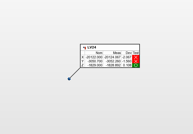
First, as a quick test of the alignment we took a look at old IAS monument LV24. This monument was used to align the WHAM2 ISI during aLIGO install, and its nominal X,Y coordinates are [-20122.0, -3050.7] mm (there is no z-axis coordinate as we were not setting these in Z back then, a separate set of wall marks was used for z-axis alignment). The results are shown in the 1st attached picture; again, ignore the z-axis results as I had to enter something for the nominal or PolyWorks wouldn't accept the entry, so I rounded to the closest whole number (this isn't even the surface of the monument, it's the point 2" above it where the SMR was, due to use of the Hubbs Center Punch Nest (which has a 2" vertical offset when using a 1.5" SMR)). Knowing how we had to set these older monuments, since I'm one of the people that set them, I'm not entirely surprised by the X and Y deviations. The monuments we set for aLIGO install (the LV monuments) were placed w.r.t. a set of monuments used to align iLIGO, which themselves were placed w.r.t. the monuments used to install the vacuum equipment during facility construction (the PSI monuments), which themselves were placed w.r.t. the BTVE monuments which define the interface between the arm beam tubes and the LVEA vacuum equipment, which we then found errors in their coordinates during our alignment of the FARO during the O4a/b commisioning break in 2024. Not at all surprised that errors could have stacked up without notice over all of those monuments set off of monuments set off of monuments set off of... Also, take note of the x-axis coordinate of this monument, this will be important later.
We then set about taking measurements of the passive stack optical table. To map the bolt holes we measured we used an XY cartesian basis, assuming the bolt hole in the -X/-Y corner was the origin. We then proceeded to increment the number by the bolt hole (not distance), following the same XY axis layout used for the IFO. Using this scheme the bolt holes for the table corners were marked as:
- -X/-Y: (0,0)
- -X/+Y: (0,32)
- +X/-Y: (36,0)
- +X/+Y: (36,32)
We were able to get measurements for bolt holes (0,0), (14,0), and (25,0). We were in the process of measuring bolt hole (36,0) (the +X/-Y corner bolt hole) when the FARO's climate sensor died.
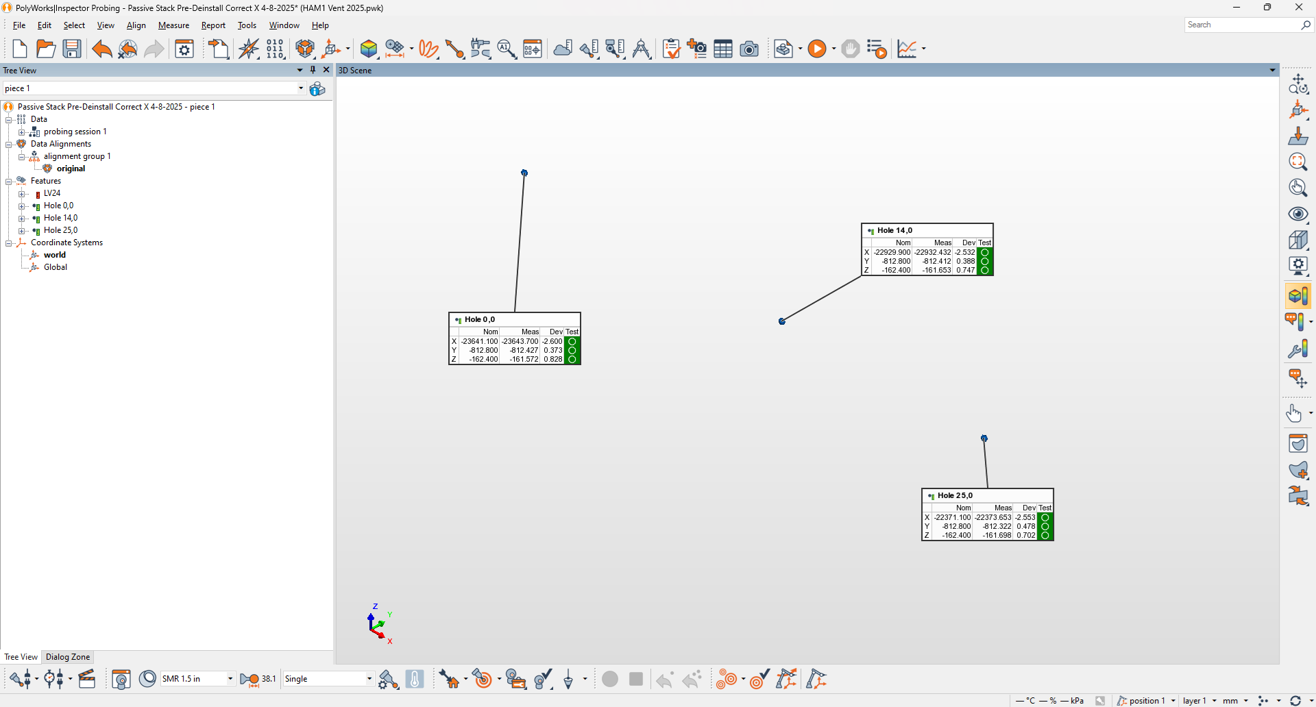
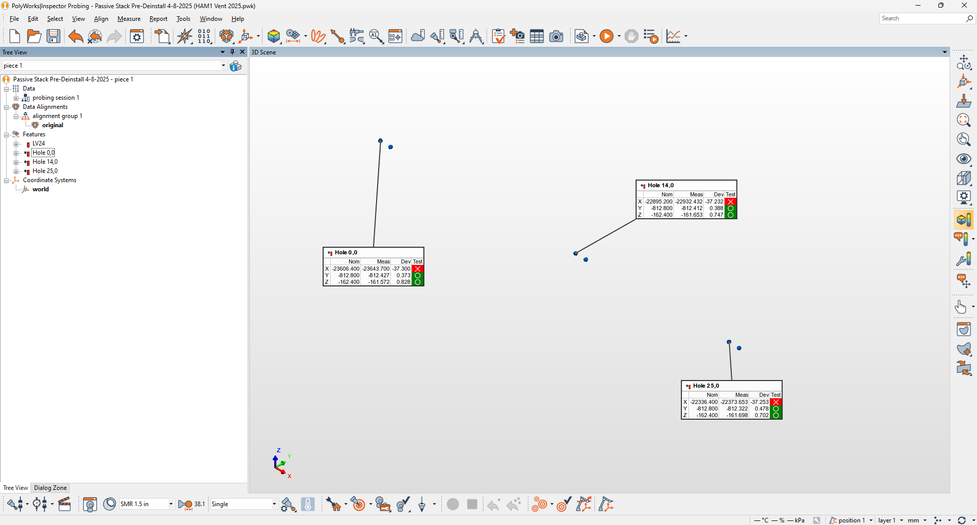
To get the coordinates for the bolt holes I used the .EASM file for WHAM1 with the passive stack configuration located at D0901821-v4. From the assembly, using eDrawings, I was able to get coordinates w.r.t. the chamber origin for the bolt holes we measured. Those were then added to the coordinates for the WHAM1 chamber, in the LVEA local coordinate system, to get nominal coordinates for the bolt holes. I also had to add 25.4 mm to the z-axis coordinates to account for the 1" offset of the nest we were using for the SMR; the center of the SMR sits 1" above the point being measured, so I needed to manually add that offset to the nominal z-axis coordinate of the bolt hole. For reference, according to D0901821 the global coordinates for WHAM1 are [-22692.0, 0.0, 0.0] mm; when converted to the LVEA local coordinate system (removing the 619.5 µrad downward tilt of the X-arm) this becomes [-22692.0, 0.0, +14.1]. The measurement results are shown in the 2nd attached picture. Notice those x-axis deviations? Remember the measurement we made of LV24? Clearly the FARO alignment is not 37 mm off, as the measurement of LV24 showed, so something is definitely up with the x-axis coordinate of the WHAM1 chamber (error in chamber placement? aLIGO WHAM1 is the iLIGO WHAM2 chamber, moved from its old location next to WHAM3).
Results
We can do some analysis of the numbers we have, although limited since we only have 3 points in a line. This really only applies to the furthest -Y line of bolt holes on the table, since we weren't able to get measurements of the +Y side to get a more full picture of where the table is sitting, but it's something. Position tolerances at install in 2012 were +/-3.0 mm in all axes.
- X-axis position: Not much we can do here without knowing what the actual x-axis coordinate of WHAM1 is. It clearly isn't where the SYS drawings say it should be.
- Y-axis position: ~0.41 mm +Y from nominal
- Z-axis position: ~0.76 mm +Z from nominal
- Pitch: ~99 µrad down
- Yaw: ~83 µrad CCW
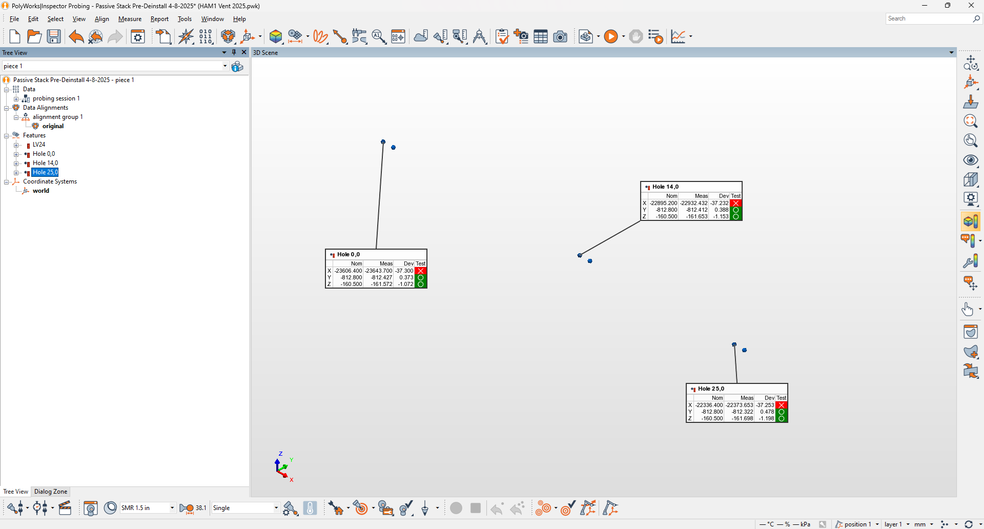
I do want to note that D0901821-v4 claims the table surface should be -187.8 mm in LVEA local coordinates (-201.9 mm in global), but this is not the number we used when installing the passive stack in 2012. In 2012 we used -185.9 mm local (-200.0 mm global), as can be seen in D0901821-v2. To compare our measurements to the install numbers I changed the nominal z-axis coordinate to match that of our install target (-185.9 + 25.4 mm SMR offset = -160.5 mm) and the results are shown in the final attached picture.
Wall Scale Registered to Current Table Surface Elevation
To finish, we set a scale on the -Y wall directly Crane East of the WHAM1 chamber and registered it to the current elevation of the passive stack's optical table. To do this we used a scale provided by Jim (the scale was in inches, with 0.01" tick marks) and an autolevel. We set the autolevel at a fixed elevation on the -Y side of the chamber. The scale was then placed at each corner of the optical table, starting with the -X/+Y corner, and the autolevel was used to sight the scale; only the scale was moved, the autolevel was fixed (rotated only to follow the scale, but not moved otherwise). We then averaged the 4 scale readings to get the table elevation, set the autolevel to this reading with the scale back at our starting point (we actually didn't have to move it, thankfully), and then set a scale on the wall using the autolevel. The 4 scale readings:
- -X/-Y: 5.89"
- -X/+Y: 5.90"
- +X/-Y: 5.90"
- +X/+Y: 5.91"
The average of the 4 readings is 5.9", and since the autolevel was already sighting 5.9" on our starting point at the -X/+Y corner we left it there. This may seem high, but we had to have the autolevel high enough that we could see over the various components mounted to the table surface. We then turned the autolevel and set a scale on the wall. This scale was in mm (since that's what we had), but this worked out OK. 5.9" is ~149.9 mm (149.86 mm to be exact), so we set the wall scale so it read ~149.9 mm when sighted through the autolevel. So a 150.0 mm reading on this scale (sighting the side with the 0.5 mm tick marks) is ~150.0 mm above the current position of the passive stack's optical table.
This closes LHO WP 12442.
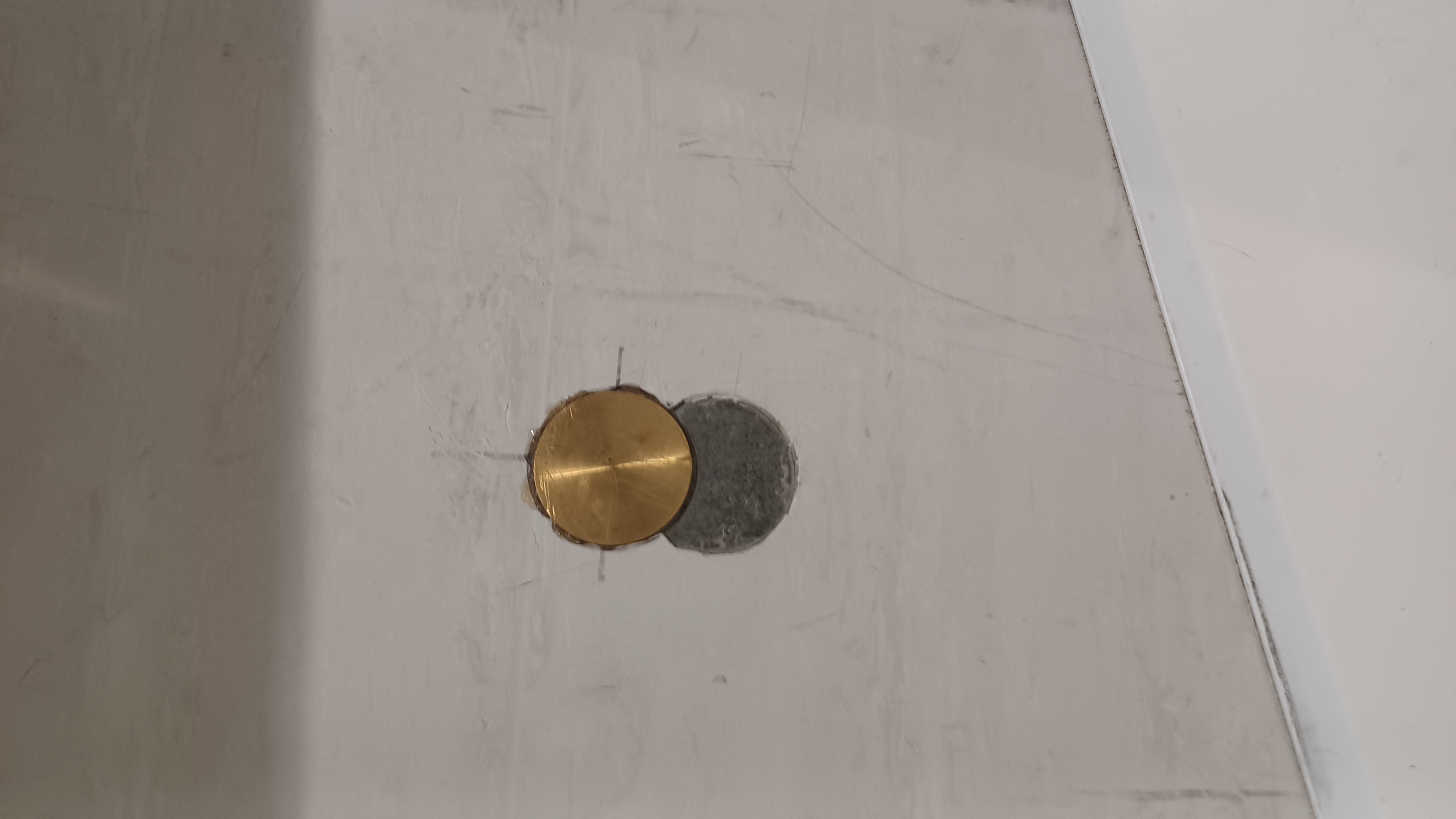
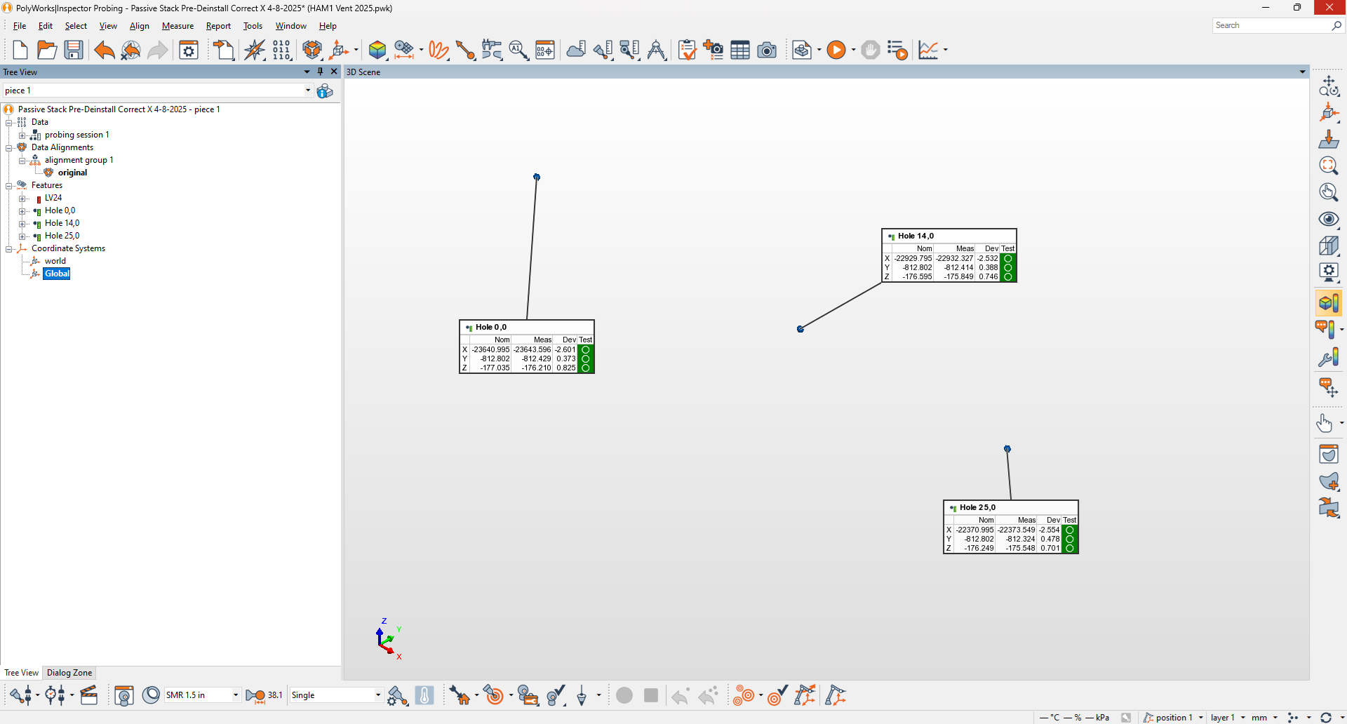
TJ O'Hanlon informed me via email that there indeed was an error in the x-axis coordinate at both LHO and LLO, due to the thickness of the septum between HAM1 and HAM2 not being taken into account, which had not been propagated to all of the SYS mechanical layout drawings (and some of the CAD files as well). I had completely forgotten about this, and explains why we had moved the WHAM1 passive stack monument LV25 further in the -X direction some time back in 2012; the first attached picture shows this (the clear cut out next to the existing monument was the old position of LV25 before we moved it). I went spelunking through my old 2012 emails to find some communication about this, but all I could find was an email chain re: LLO setting the LHAM6 support tubes and not being able to get them in the proper y-axis position. Dennis replied that this was due to the septum thickness and would apply to HAM1 and HAM6 at both sites, and that he would update E1200625 with the correct coordinates for all involved chambers. From E1200625 the x-axis coordinate of WHAM1 should be -22726.7 mm, so I have updated the PolyWorks project with this new, correct coordinate; this is shown in the 2nd attached picture.
From this I can now say that the -Y row of holes on the WHAM1 passive stack's optical table are ~2.56 mm too far in the -X direction. If we were to use the FARO to survey monument LV25 my guess is that would explain the 2.5 mm error, seeing as how nearby LV24 was also ~2.0 mm too far in -X direction. As stated in the main alog this difference doesn't exactly surprise me given the "monuments placed off of monuments placed off of monuments" situation we have here. The FARO was aligned to our X and Y axes using monuments PSI-1, PSI-2, PSI-6, and BTVE-1, so any error between these 1st and 2nd generation monuments and the 4th generation LV monuments will be measured by the FARO.
While I was at it I went ahead and applied the required transform for local to global coordinates. This is done by creating a new coordinate system and applying the requisite tilt of both the X and Y axes. The tilt must be entered in degrees and for the opposite axis. This is because our, for example, y-axis tilt angle w.r.t. local gravity is a rotation of the x-axis. Since PolyWorks works off of axis rotation, we enter the y-axis angle as an x-axis tilt (same for the x-axis angle). To get PolyWorks to correctly calculate the transform matrix both values should be entered as positive numbers (I'm not entirely sure why). The values to enter:
- X-axis rotation: 0.0000125 µrad -> 0.0007162°
- Y-axis rotation: 0.0006195 µrad -> 0.0354947°
The calculated transform matrix is shown in the 4th attached picture, which properly matches Table 10 in T980044 (note, the numbers in the transform matrix are in radians, even though I had to enter the rotations in degrees). To confirm this was correct I manually calculated the correct global z-axis coordinate using the formula in Section 2.3 of T0900340 for each bolt hole; the results were the same between my calculation and PolyWorks'. The final picture shows the bolt hole survey in the LHO global coordinate frame.