I took transfer functions for ITMY's M0 and R0 to check for any rubbing that might have been caused by the negative pitch adjustment made to R0 (83865). Most importantly, we wanted to make sure that a negative pitch offset in the R0 OPTICALIGN OFFSET sliders wouldn't cause R0 to hit anything when driven. The negative pitch means that R0 is tilted away from M0, so the bottom of R0 juts towards the bottom of M0.
First I took a set of regular R0 transfer function measurements with the R0 offset sliders at 0. These look good.
I then set the R0 Pitch offset slider to -250, which we are unlikely to go past (typically that slider is set to mid +200s). We called this the 'closest approach'. I wasn't able to set the slider to its full offset of -440, because then the DAC range is so limited that we aren't able to drive it to take any measurements. These transfer functions also all look good. We especially made sure that Pitch was looking good and not rubbing anywhere.
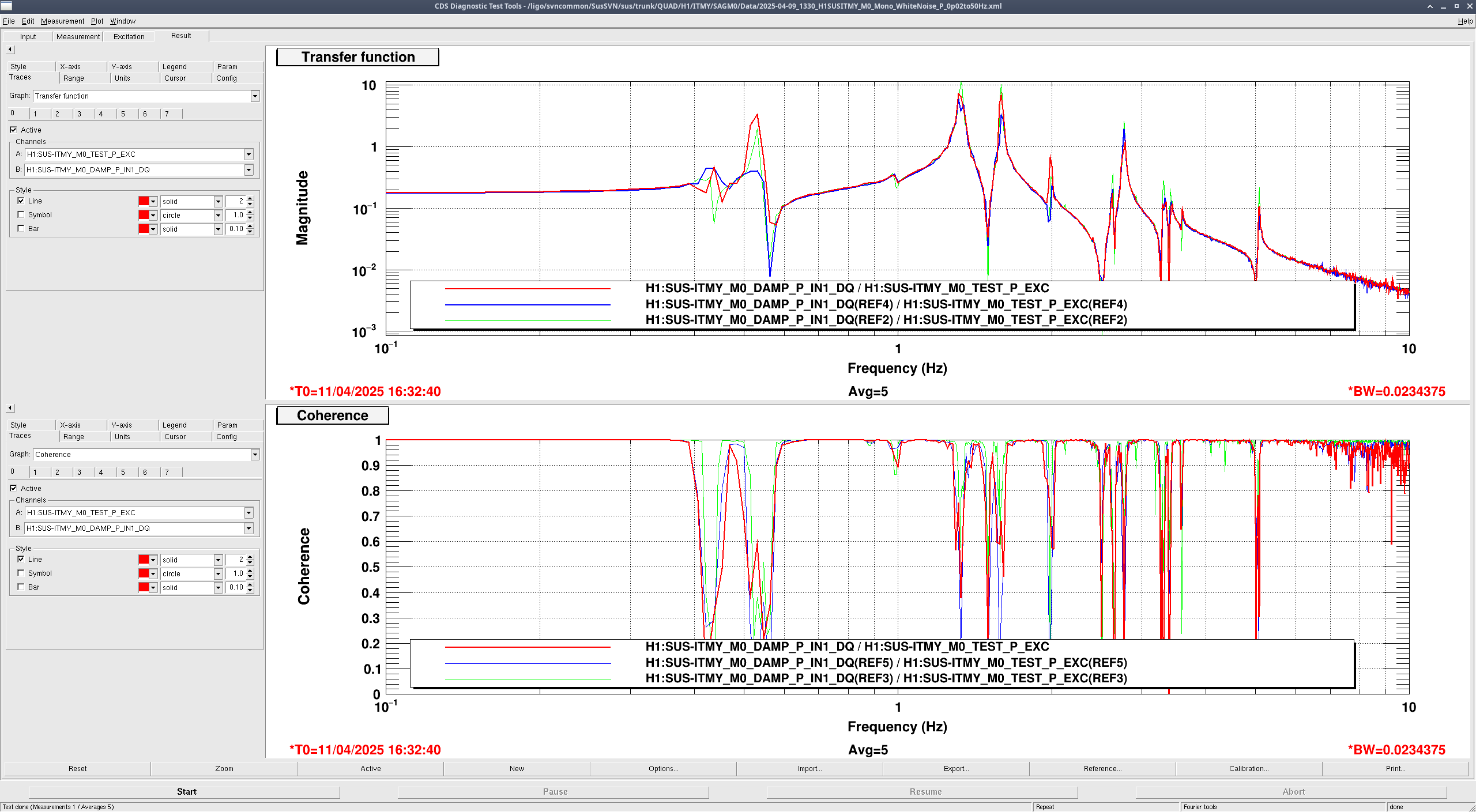
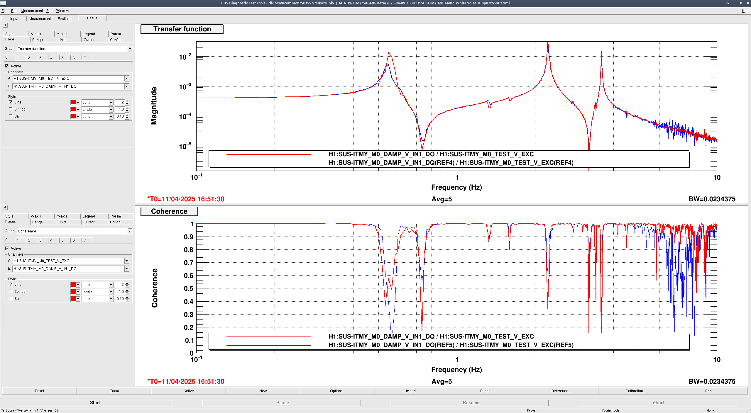
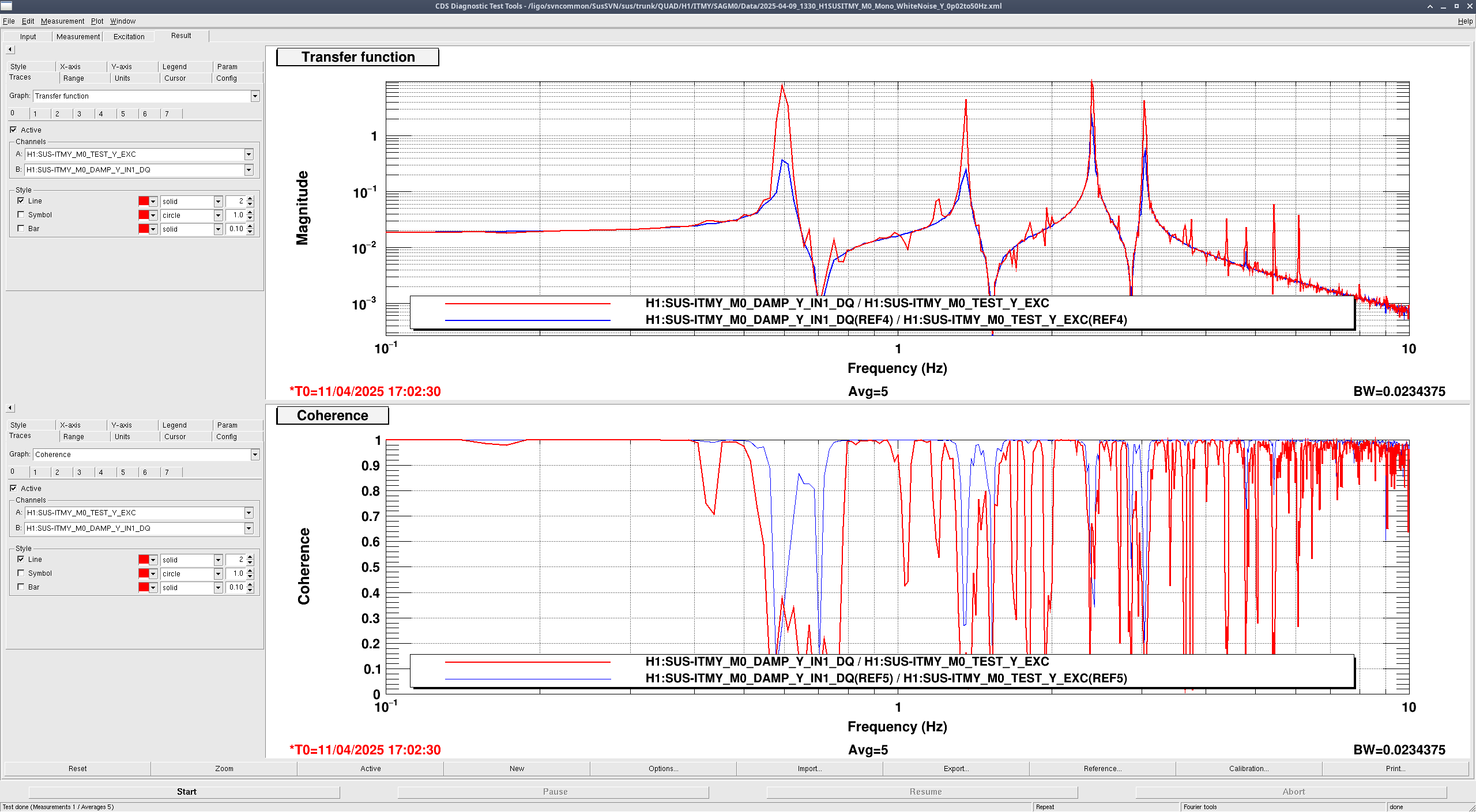
To be even more certain that we weren't going to end up with anything touching, we ran a few transfer functions on M0 with a 'double closest approach' setup. With the R0 Pitch slider still set to -250, I changed the M0 Pitch slider to +250, tilting the bottom of M0 towards the bottom of R0, putting them even closer. I then checked Pitch, Vertical, and Yaw, with Pitch being the most important in telling us whether we were anywhere near close to having them hit anything. Those also all came back clean (Yaw looks weird but Jeff assured me that that's due to cross-coupling movement that went away when we reran it with damping loops on*).
We are confident that the adjustments made in the chamber didn't put us at risk of rubbing, and so doors are clear to go on. Once doors are back on we will check again.
These measurements have been committed to svn and can be found at:
.../QUAD/H1/ITMY/SAGR0/Data/2025-04-10_1800_H1SUSITMY_R0_WhiteNoise_{L,T,V,R,P,Y}_0p01to50Hz.xml r12208
.../QUAD/H1/ITMY/SAGR0/Data/2025-04-10_2200_H1SUSITMY_R0_WhiteNoise_{L,T,V,R,P,Y}_0p01to50Hz.xml r12208
.../QUAD/H1/ITMY/SAGM0/Data/2025-04-11_1600_H1SUSITMY_R0_WhiteNoise_{V,P,Y}_0p02to50Hz.xml r12212
Results have been committed to svn and can be found in:
.../QUAD/H1/ITMY/SAGR0/Results/2025-04-10_1800_H1SUSITMY_R0_ALL_TFs.pdf r12210
.../QUAD/H1/ITMY/SAGR0/Results/2025-04-10_2200_H1SUSITMY_R0_ALL_TFs.pdf r12210
* Full explanation from Jeff: "the 'weirdness' in yaw is the several frequency points where the reference looks smooth as a function of frequency between resonances, and the new data has 'lots' of single-data-point excursions from that smoothness. I attribute this to lack of coherence, and lots of motion on the QUAD. Yaw is a differential measurement of F2 and F3. We’re already having to drive less than normal because we have large offsets on. But also, we typically see that since there’s lots of motion, the imperfect calibration of the F2 and F3 sensors shows up, and lots of other DOF’s resonances show up at a low level where they shouldn’t. Turning on the damping loops and measuring again with them on is the confirming evidence that this is what’s going on. We took the same TF with the R0 and M0 chains damped and they look good."

| Measurement | Mass? | R0 OPTICALIGN OFFSET Pitch value | M0 OPTICALIGN OFFSET Pitch value | Description |
| 2025-04-10_1800 | R0 | 0 | -108 (nominal) | nominal |
| 2025-04-10_2200 | R0 | -250 | -108 | R0 closest approach; R0 bottom tilted towards M0 |
| 2025-04-11_1600 | M0 | -250 | +250 | R0, M0 both closest approach; bottoms tilted towards each other |
Adding a PDF of the M0 measurements taken earlier, along with L, T, and R for M0 taken in that same configuration. These cannot be analyzed because they were taken with a different bin width, but more official measurements will be taken next week.
These extra measurements have been committed ot the svn and can be found at:
.../QUAD/H1/ITMY/SAGM0/Data/2025-04-11_1600_H1SUSITMY_R0_WhiteNoise_{L,T,R}_0p02to50Hz.xml r12215