TJ, Sheila, Matt, Andrew (job shadow today), Camilla. WP12433. Table layout D1400241.
Following on from other beam profile work at the end stations 81358, Madi Simmonds models G2500646 and the ideas we had for understanding ETM mode matching better (googledoc), today we took some beam profiles of the EY ALS beam reflected of ETM HR in the HWS path.
We added a 532nm quarter waveplate downstream of the beamspiltter (ALS-M11) and tuned it to maximize the light reflected into the HWS path. This was removed when we were finished and left with Nanoscan beam profile.
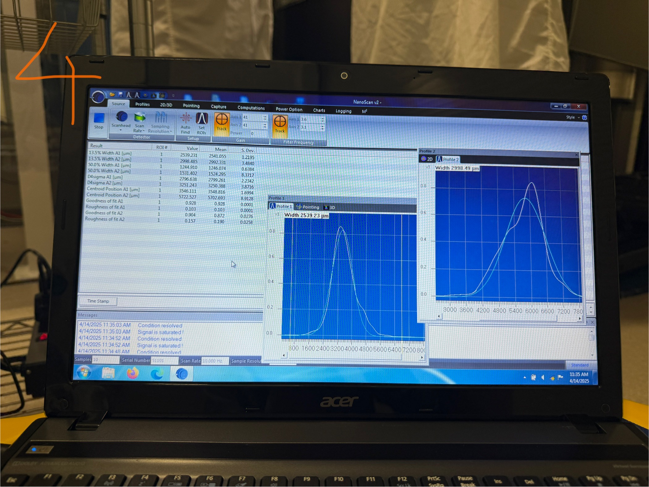
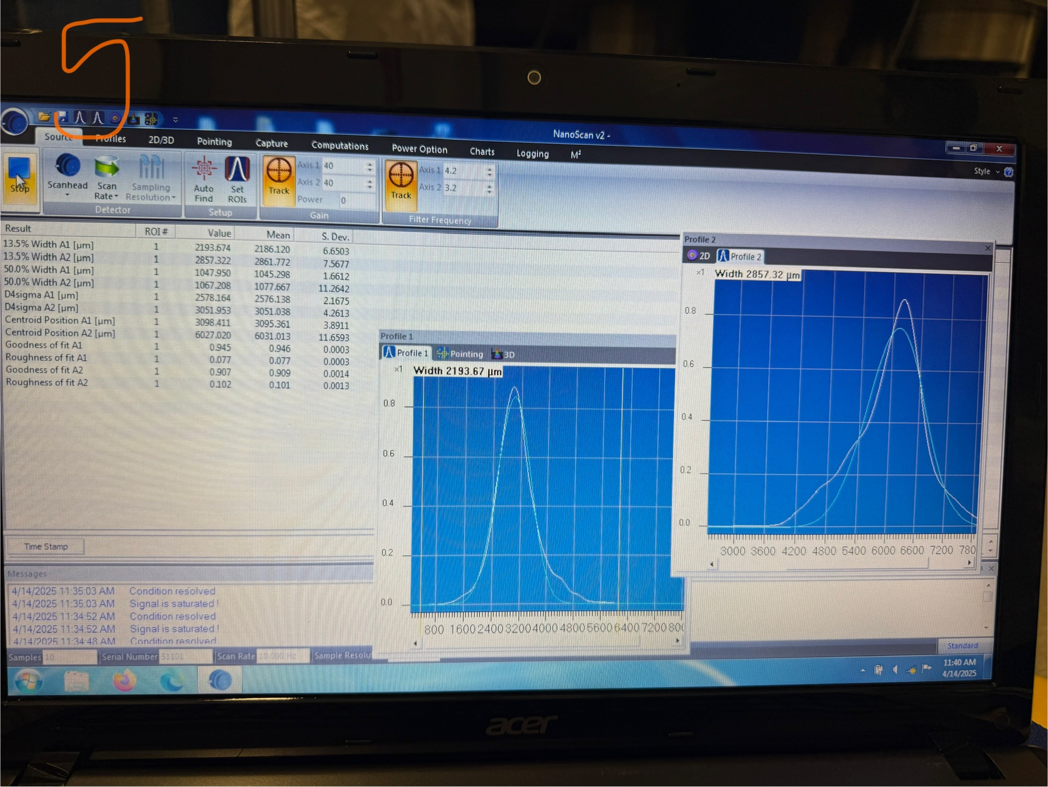
We first took some beam profile measurements (photos 1-4) first with the QPD offsets on nominally, and then with the offsets zero'ed (phots 5-9). Unless the beam has been pico-ed (which it may have) the zero offsets should have the beam more centered on the Transmon parabolic mirrors. The beam changed when the offsets were turned off but did not look better/worse, just different. Compare photo 4 (QPD offsets on) and photo 5 (offsets off).
|
Photo
#
|
|
A1 horizontal
13.5%
|
A2 vertical
13.5%
|
A1 horizontal
50%
|
A2 vertical
50%
|
| Started with QPDs on at thier usual values: | |||||
|
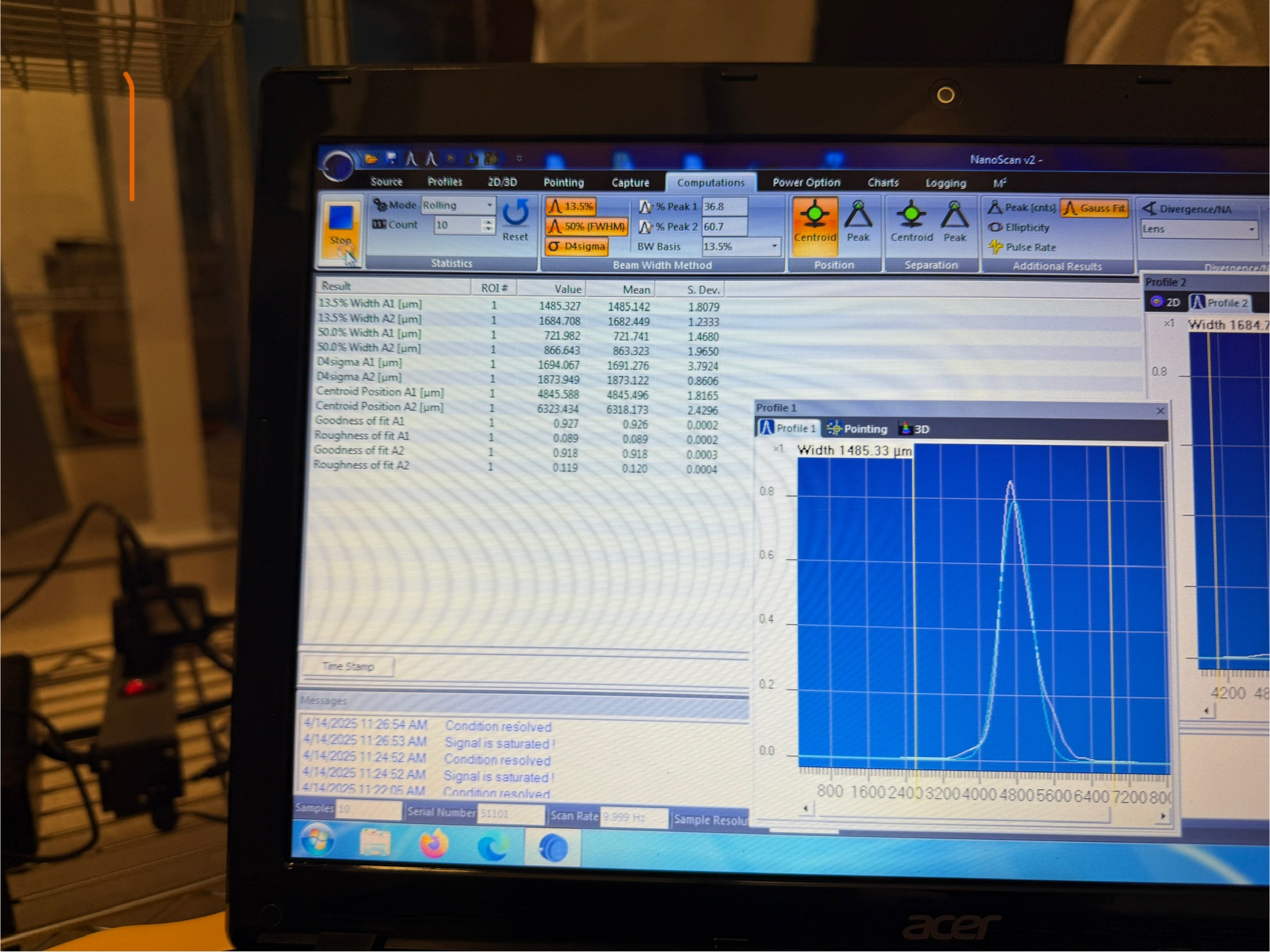
1
|
50.5cm downstream of HWS-M3 (between M3 and M4)
|
1485
|
1685
|
723
|
871
|
|
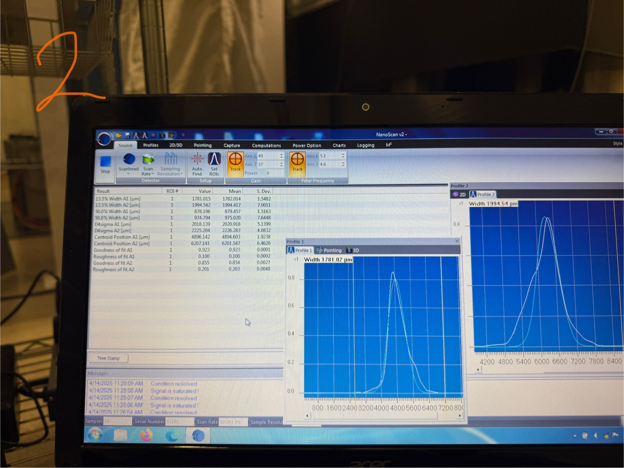
2
|
42.5cm downstream of HWS-M3 (between M3 and M4)
|
1783
|
1985
|
877
|
970
|
|
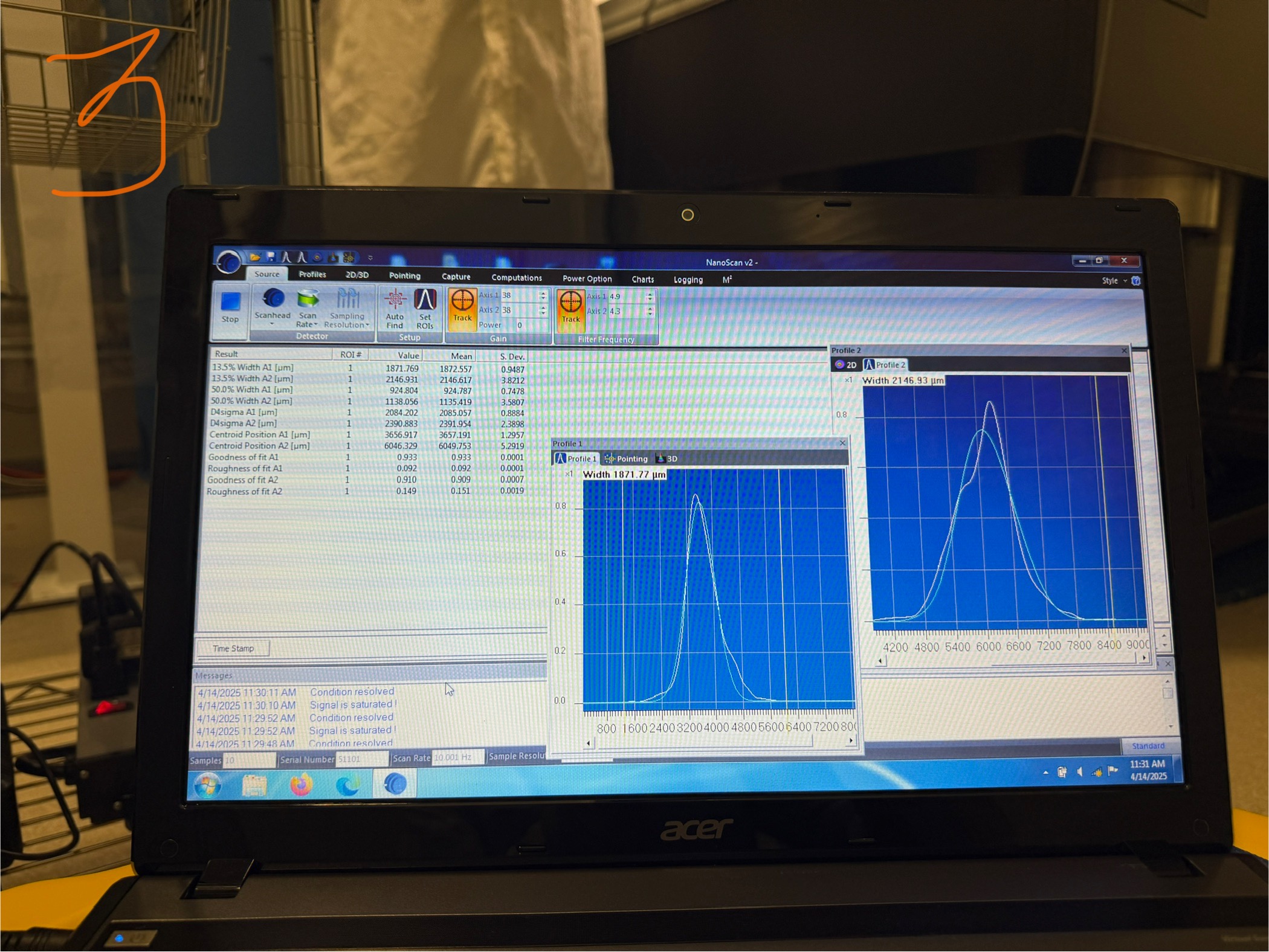
3
|
36.5cm downstream of HWS-M3 (between M3 and M4)
|
1872
|
2146
|
924
|
1135
|
|
4
|
13.0cm downstream of HWS-M3 (between M3 and M4)
|
2540
|
2991
|
1247
|
1516
|
|
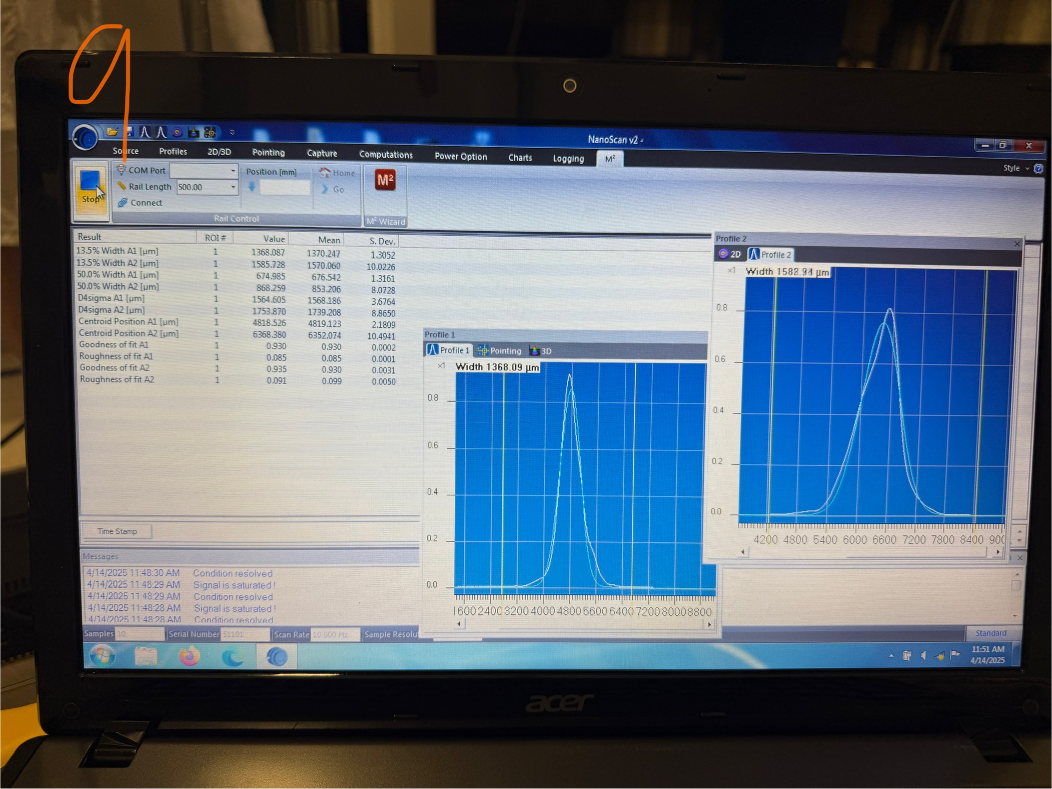
Then we turned off QPD offsets and retook data:
|
|||||
|
9
|
51cm downstream of HWS-M3 (between M3 and M4)
|
1370
|
1570
|
676
|
853
|
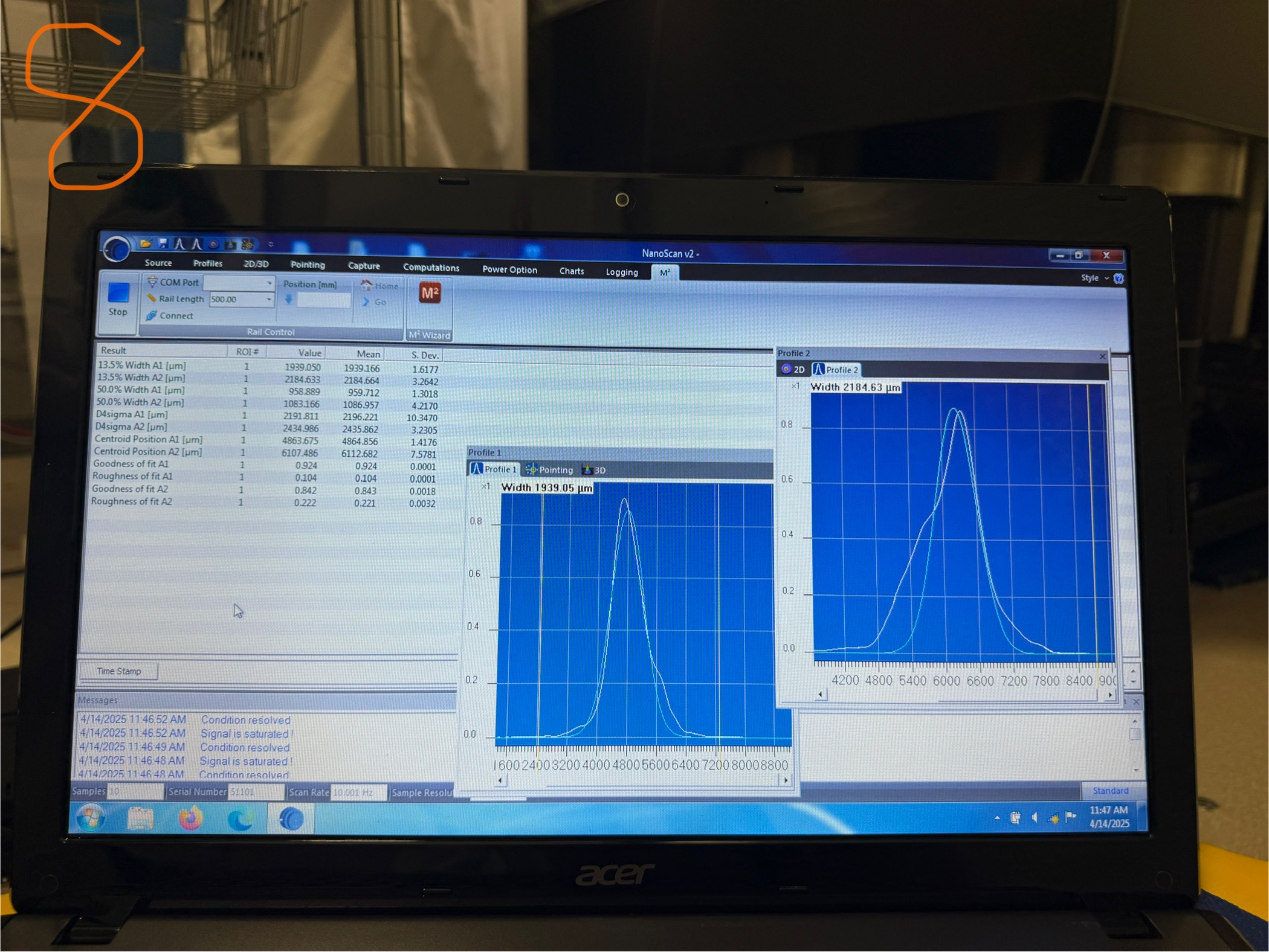
|
8
|
33.5cm downstream of HWS-M3 (between M3 and M4)
|
1939
|
2184
|
959
|
1086
|
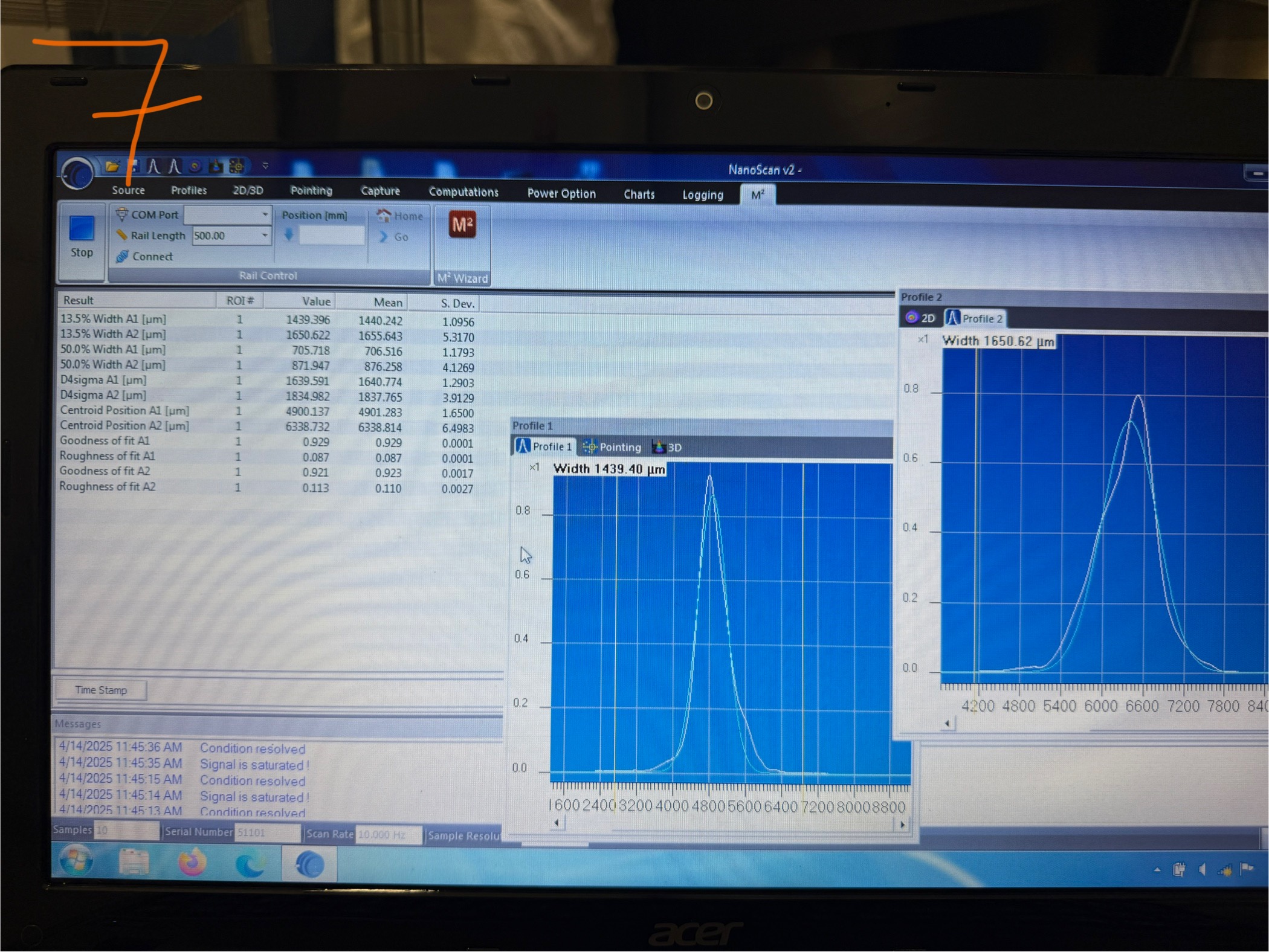
|
7
|
48.5cm downstream of HWS-M3 (between M3 and M4)
|
1440
|
1655
|
706
|
876
|
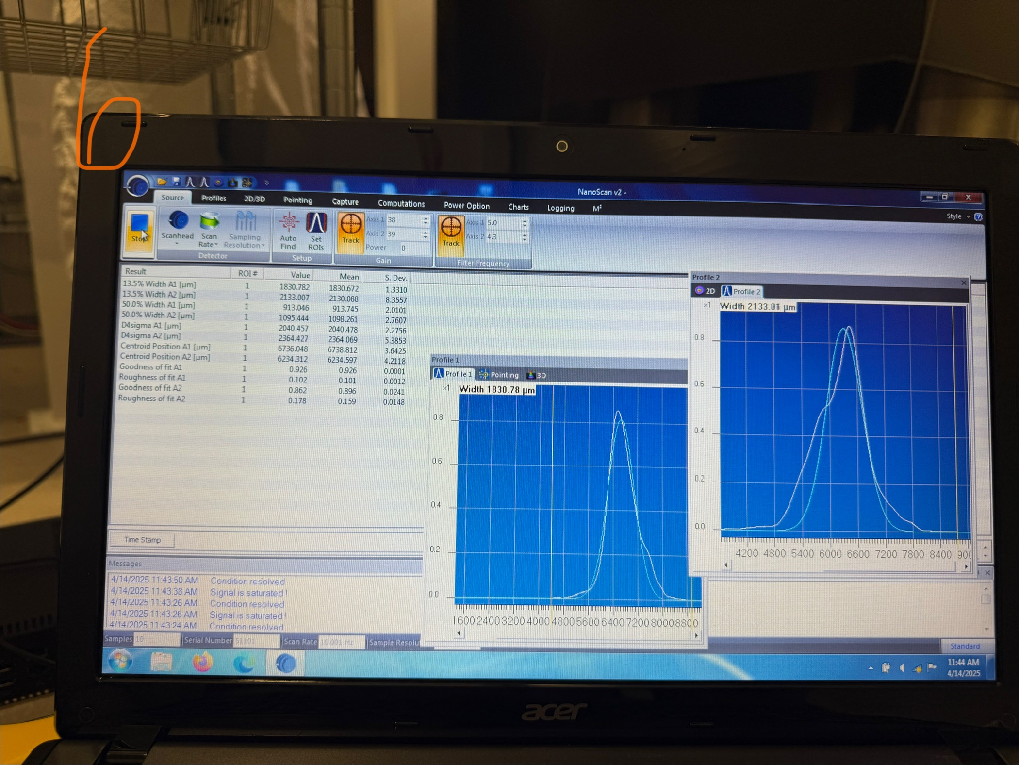
|
6
|
36cm downstream of HWS-M3 (between M3 and M4)
|
1830
|
2130
|
913
|
1098
|
|
5
|
13.0cm downstream of HWS-M3 (between M3 and M4)
|
2186
|
2861
|
1045
|
1077
|