Displaying report 1-1 of 1.
Reports until 16:03, Tuesday 15 April 2025
H1 PSL (ISC, SQZ)
jeffrey.kissel@LIGO.ORG - posted 16:03, Tuesday 15 April 2025 - last comment - 12:18, Wednesday 16 April 2025(83933)
SPI Pick-off Path Installation Begun
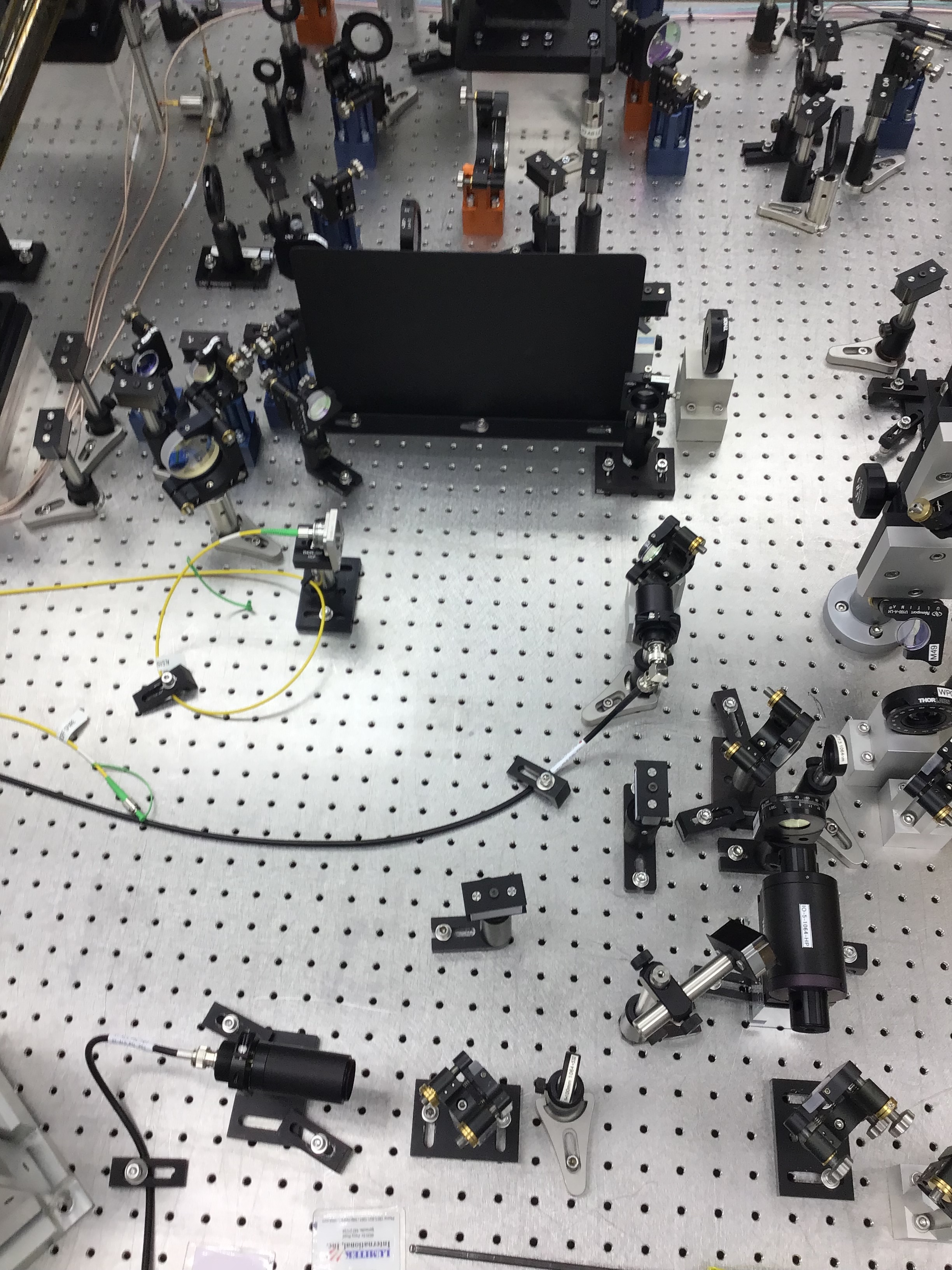
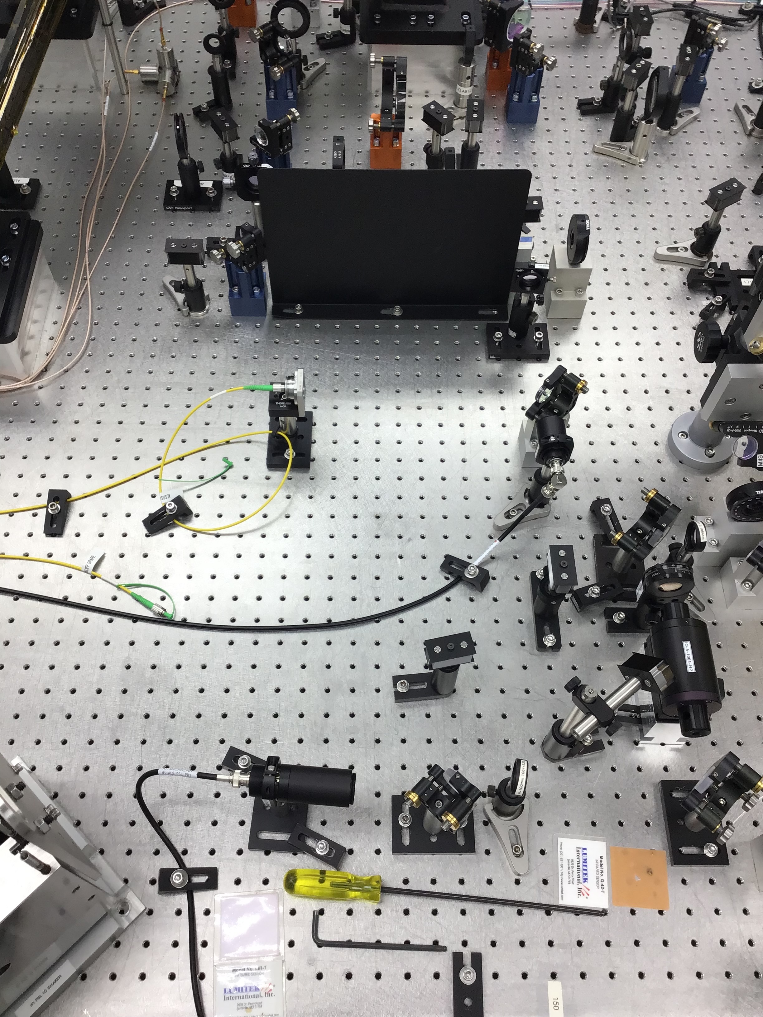
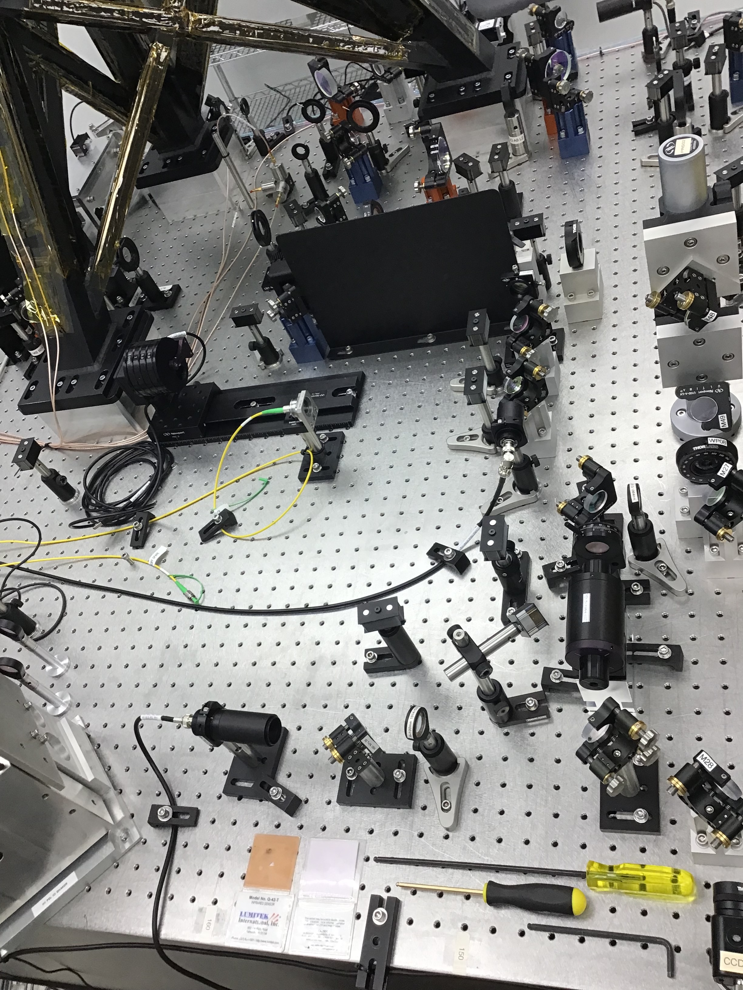
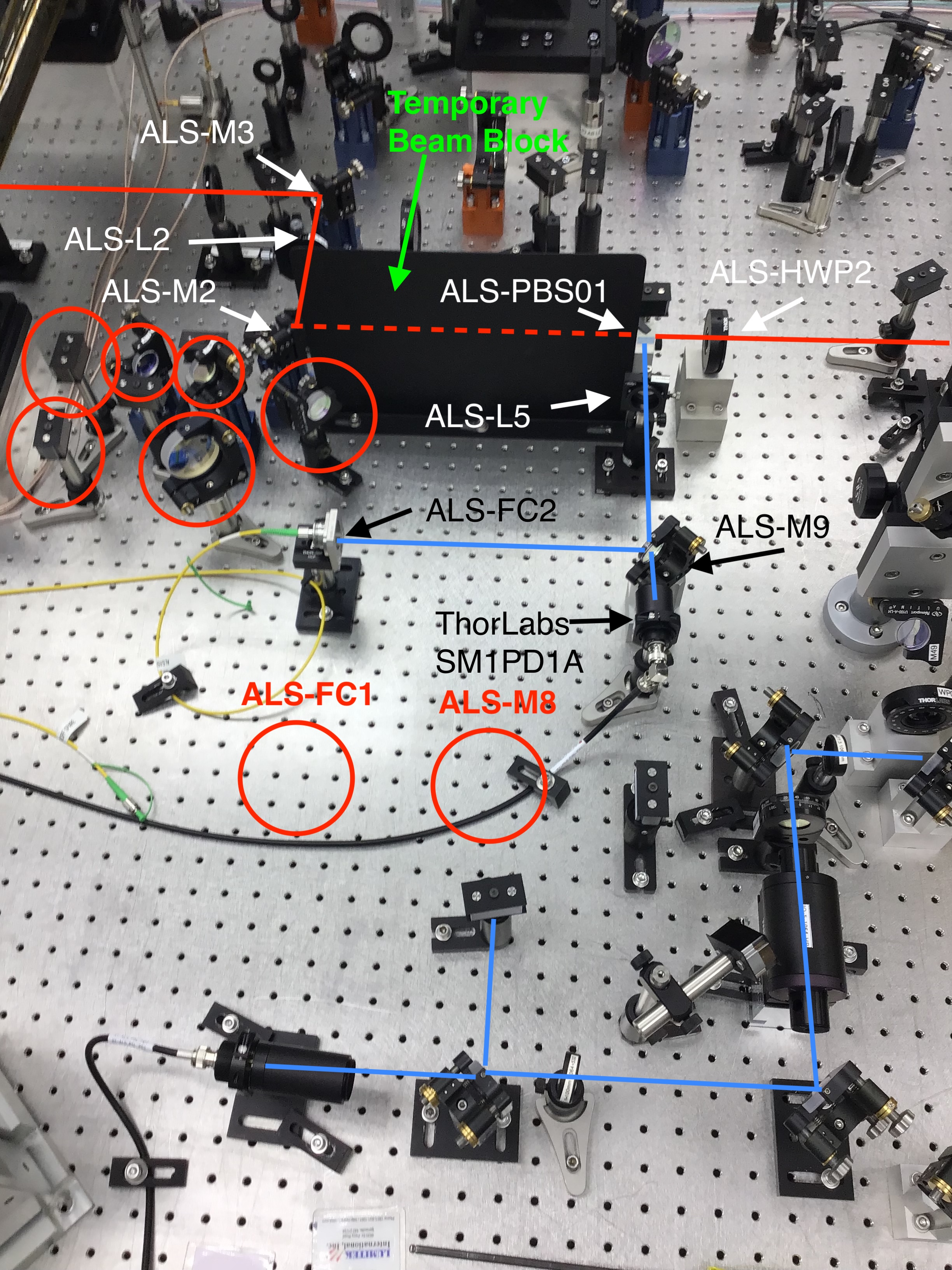
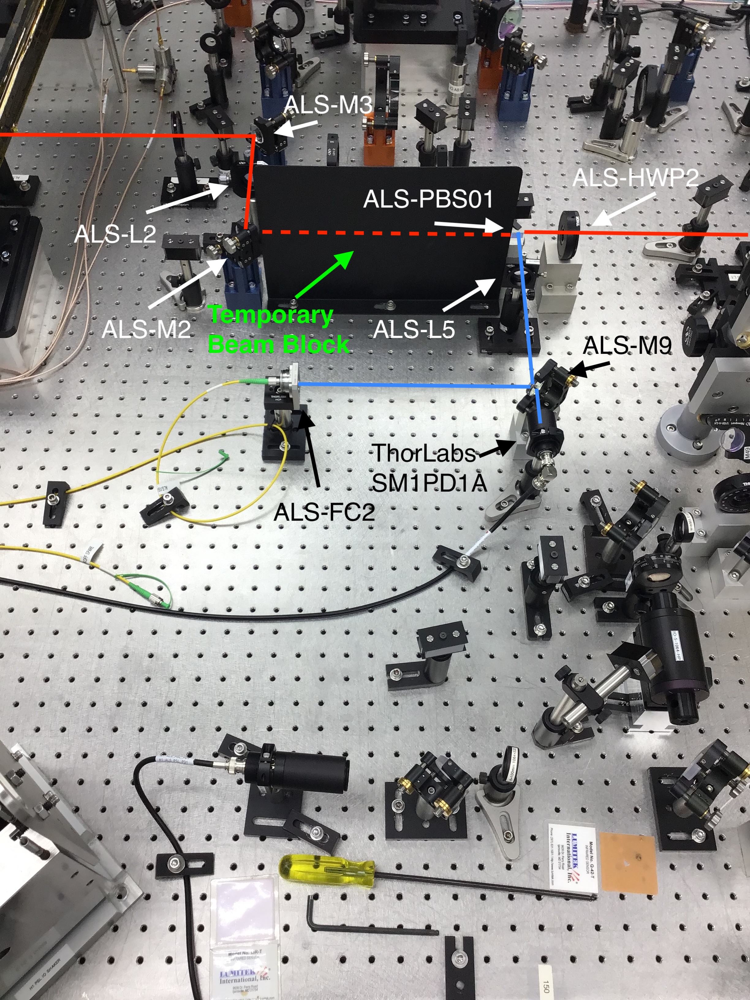
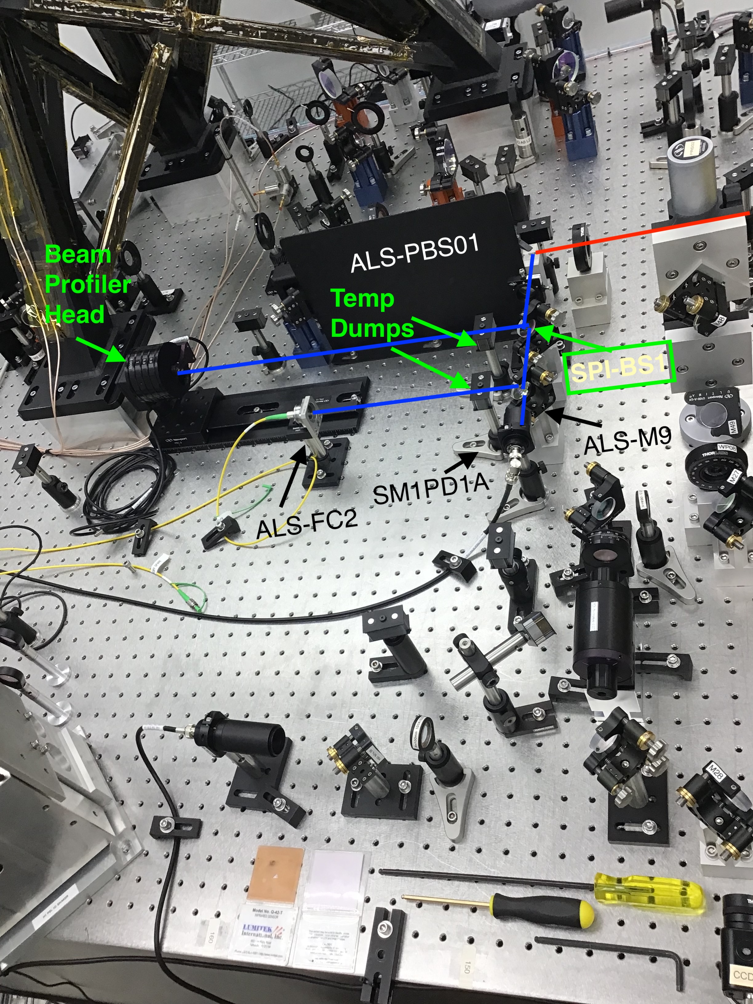
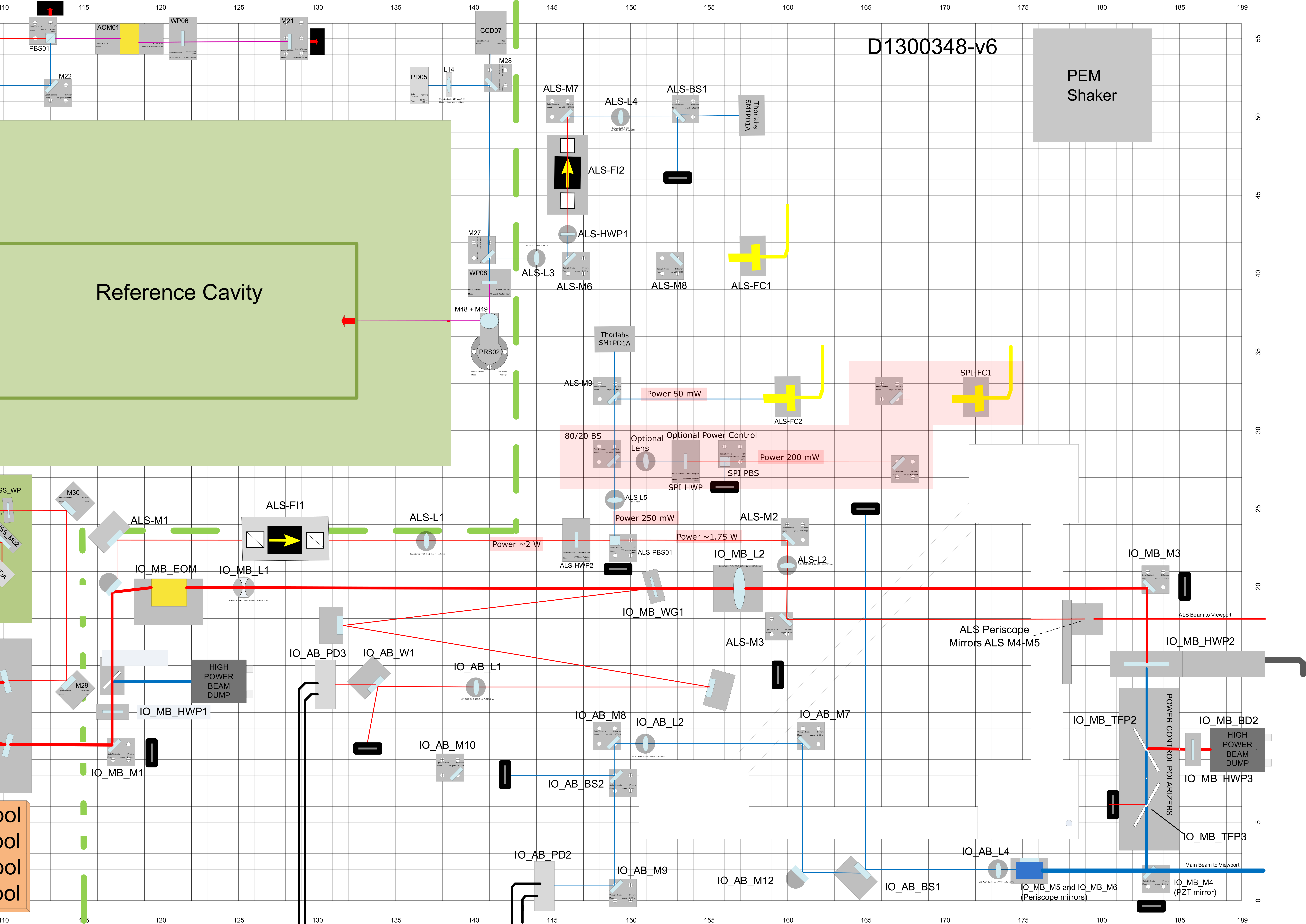
J. Kissel, S. Koehlenbeck, J. Oberling, R. Short, J. Freed
ECR E2400083
IIET 30642
WP 12453

After this morning's kerfuffle / belated power-outage recovery with the PSL HVAC system was resolved, Sina, Ryan, and Josh began the procedure we're walking thru outlined in Section 1 of T2500024. We're keeping running notes on the fly at the bottom of the google-doc for now.

In summary here, with more details to come, we got as far as 
- Clearing out some old IO equipment that unused and in the way of the SPI pick-off path
- Measuring the power around ALS-PBS01
- Installing the new ALS/SPI 80R/20T beam splitter
- Measuring the beam profile along the future SPI path, in reflection of this 80R/20T beam splitter.
Comments related to this report
jeffrey.kissel@LIGO.ORG - 08:48, Wednesday 16 April 2025 (83946)CSWG, SEI, SYS
Among the first things we did was measure the power at various places along the ALS beam path to get a good starting point. 

For the ~2W beams we used an Ophir 20C-SH (datasheet says accuracy of +/- 3%) and for ~100 mW beams we used a S401C, (datasheet says accuracy of +/- 7%). 

For laser safety, we would unlock the PMC and shutter the laser while we were placing these power meters, so I also kept track of the PMC TRANS to scale our measurements by input power appropriately.
We did NOT turn on the PMC's intensity stabilization servo (ISS), for no particular reason other than we forgot to turn it on for the first measurement, and then wanted to stay consistent. 
This meant that the PMC TRANS itself was slowly noise at that +0.5 [w] level, so my reported values below are "eyeball averages."

So, not exactly a NIST-level precision/accuracy setup, but good enough for sanity checks. As such, I'm not going to bother report uncertainty in the numbers below.

Here're the results (again, this is prior to doing anything to the path).
Times of measurements are all for 2025-04-15, and in UTC, such that trends of other PDs may be captured if need be.
    Location                               Power Meter [mW]         PMC Trans [W]       Time [UTC]
    (1) Going in to ALS-HWP2                   2060                    103.2              21:39     # expected: 2000 [mW]; good!
       (between ALS-L1 and ALS-HWP2)      

    (2) p-pol in trans of ALS-PBS01            1970                    102.8              22:17     # expected: 1950 [mW]; good!
        (between ALS-M2 and ALS-L2)          
    
    (3) s-pol in refl of ALS-PBS01               49.4                  103.2              21:44     # expected: 50 [mW]; good!
        (between ALS-L1 and ALS-M9)            
    
    (4) s-pol in refl of ALS-M9                  47.7                  103.0              21:48     # 44.9 [mW] reported by ALS-C_FIBR_EXTERNAL_DC_POWERMON, which is in trans of ALS-M9 at this time; good!
       (between ALS-M9 and ALS-FC2) 

All of these powers match expectation quite exquisitely. My guess for the inconsistency of (4) with the EXTERNAL monitor PD is that the beam splitter ratio of ALS-M9 programmed into the beckhoff calibration of the PD's channel is a bit off, but this can be cross-checked later.

We then installed SPI-BS1 (the 80R/20T BS), and cross-checked the reflectivity reported in LH0:83863.
    Location                               Power Meter [mW]         PMC Trans [W]       Time [UTC]
    (5) s-pol in refl of SPI-BS1                 37.7                  102.4              22:22

The PMC power is lower between (3) and (5), the input to the SPI-BS1 is different, so we need to scale the measurement a bit,
    Input Power to SPI-BS1 = 49.4 [mW] * (103.2 / 102.4) = 48.81 [mW]
    REFL power from SPI-BS1 = 37.7 [mW]
    
    Fractional reflection = 37.7 [mW] /  48.81 [mW] =  0.772 = 77%
    (from LHO:83863) = 77%.
Thus, our results today are consistent with what Josh and Keita measured in the optics lab.
jeffrey.kissel@LIGO.ORG - 12:18, Wednesday 16 April 2025 (83948)
Pictures from the work on 2025-04-15.

The first three attachments are without labels, just in case the pics are needed for something else in the future.

The diagram we were working with (from the SPI ECR) is also attached here for convenience.

The second three attachments *are* labeled, so I'll describe what happened using those.
20250415_some_optics_removed_labeled.jpg
- This is (mostly) the how the team started the day: with the area where the SPI pick-off path is intended to go full of un-diagrammed spare/unused stuff. I highlight red circles everything that was removed in this first attachment. Additionally, before the picture was taken, ALS-M8 and ALS-FC1 were removed and the temporary large vertical beam block was installed.

20259415_all_optics_removed_labeled.jpg
- This is the "after" all components cleared picture, and the table layout during the power measurements. As you can imagine, because of the lens tube on the SM1PD1A, there was no room between the PD and ALS-M9 to insert a power meter to measure the transmitted light  thru ALS-M9. As such, we can't validate the beam-splitting ratio of that optic. Ah well.

20250415_end_day_1_labeled.jpg
- This is how we left yesterday: We SPI-BS1 installed in its permanent location. Downstream, we sent the reflected beam into a WinCam head such that we could profile the beam incoming to the SPI path -- and assess whether we need lenses in order to adjust the beam size to match our fiber collimator. While we definitely saw the expected change in power and alignment at ALS-FC2, we elected to restore the power and alignment later.
Images attached to this comment
Displaying report 1-1 of 1.