S. Koehlenbeck, J. Freed, R. Short, J. Kissel
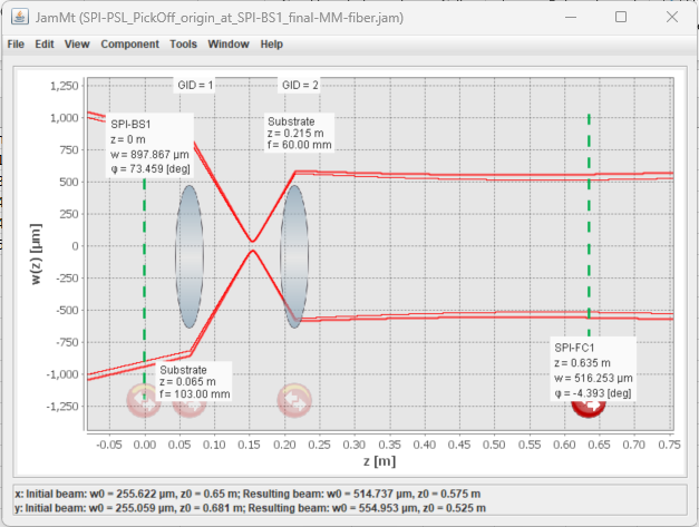
The mode matching of the PSL pick-off beam to the SPI fiber collimator has been implemented using two lenses. The target beam has a mode radius of 550 µm at a position 63.5 cm downstream from the SPI beamsplitter (SPI-BS).
The lens configuration that produced the closest match to the target mode used:
-
L1: Focal length = 100 mm
-
L2: Focal length = 60 mm
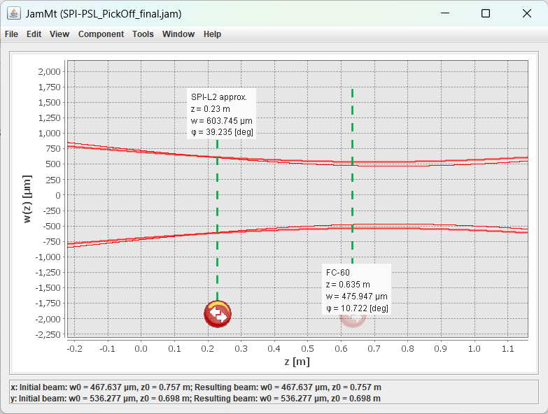
Attached is a beam profile fit performed using JaMMT on data acquired with a WinCamD of the beam after SPI-L2. The measured beam radii at various distances from the SPI-BS are as follows:
| Distance (cm) | Horizontal Radius (µm) | Vertical Radius (µm) |
|---|---|---|
| 70.734 | 476 | 542 |
| 91.054 | 470 | 543.5 |
| 116.454 | 558.5 | 616.5 |
Both lenses are oriented such that their planar sides face the small beam waist between the two lenses. The arrows on the lens mounts point toward the convex surfaces.
The power transmission through the fiber has been measured to be 83 %.
ECR E2400083
IIET 30642
WP 12453


Some "for the record" additional comments here:
- Sina refers to the "SPI-BS" above, which is the same as what we've now officially dubbed as "SPI-BS1."

- Lenses were identified to be needed after the initial measurement of the beam profile emanating from SPI-BS1. That initial beam profile measurement is cited in LHO:83956, and the lens also developed in JaMMT with the lenses that were available from the optics lab / PSL inventory.

- If anyone's trying to recreate the model of the beam profile from the two measurements (LHO:83956 with no lenses, and the above LHO:83983) just note that the "zero" position is different in the quoted raw data; in LHO:83956 is the front of the rail, on Column 159 of the table, and in LHO:83983 the zero position is the SPI-BS1 reflective surface which is on Column 149 of the table, i.e. a 10 inch = 25.4 cm difference.

- The real SPI-L1 installed to create this mode-shape / beam profile is labeled by its radius of curvature, which is R = 51.5 mm, and thus its focal length is more precisely f = R*2 = 103 mm. (We did find a lens that does have f = 60 mm for SPI-L2, and it's labeled by its focal length.)

- "the fiber" is that which is intended for permanent use, depicted as SPI_PSL_001 in the SPI optical fiber routing diagram D2400110, a Narrow Key PM-980 Optical Fiber "patch cord" from Diamond, whose length is 30 [m]. This fiber will run all the way out to SUS-R2, eventually, to be connected as the input to the SPI Laser Prep Chassis (D2400156).

- Per design, light going into this fiber is entirely p-pol, due to polarization via SPI-HWP1 and clean-up by SPI-PBS01 just upstream. We did not measure the polarization state of the light exiting the fiber.

- The raw data that informs the statement that "the power transmission thru the fiber has been measured to be 83%":
     : We measured the input to the fiber coupler, SPI-FC1, via the S140C low-power power meter we'd been using throughout the install. The output power was measured via a fiber-coupled power meter Sina had brought with her from Stanford (dunno the make of that one).

     : We measured the power input to the fiber twice several hours apart (with the change in fiber input power controlled via the SPI-HWP1 / SPI-PBS01 combo).,
         (1) 19.9 [mW] with PMC TRANS power at 104.1 [W] at 2025-04-17 16:35 UTC (while the PMC power was in flux from enviromental controls turn on)
         (2) 180 [mW] with PMC TRANS power at 103.5 [W] at 2025-04-17 14:00 UTC (while the PMC power was quite stable)

     : We measured the output power
         (1') 16.6 [mW] with PMC TRANS power at 103.7 [W] at 2025-04-17 17:35 UTC (an hour later than (1))
         (2') 150 [mW] with PMC TRANS power at 103.5 [W] at 2025-04-17 14:00 UTC (simultaneous to (2))

     : Thus derive the transmission to be
         (1'') (16.6 / 19.9) * (104.1/103.7) = 0.837 = 83.7% and
         (2'') (150 / 180) * (103.5/103.5) = 0.833 = 83.3%
In the attachment you will find the JAMMT model for the measured beam profile of the PSL pick off with the origin a SPI-BS1, as well as the lenses used to adjust the mode of the beam for the fiber collimator FC60-SF-4-A6.2-03.