Reports until 13:07, Monday 21 April 2025
H1 AOS
daniel.sigg@LIGO.ORG - posted 13:07, Monday 21 April 2025 - last comment - 15:52, Tuesday 29 April 2025(84027)
OSEM reabacks for RMs

Fil Marc Daniel

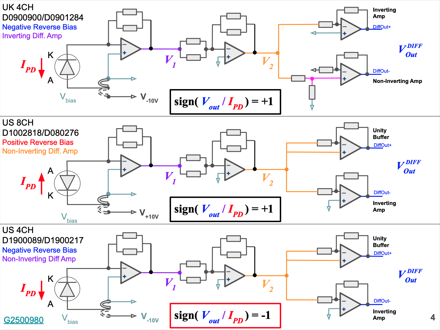
We noticed that the photodiode pins of the in-air cable that connects to RM1 and RM2 were flipped. This will flip cathode and anode which will only matter if there is a bias applied.

Going thru the schematics it seems that with 1:1 wiring the PD anode and cathode are flipped compared to what is shown in Sat Amp D080276. I assume somebody noticed this and flipped the corresponding pins of the in-air cable to correct for it back in 2013.  The polarity of the PD doesn't really matter, if there is no bias. We checked the RM sat amps and they have no bias.

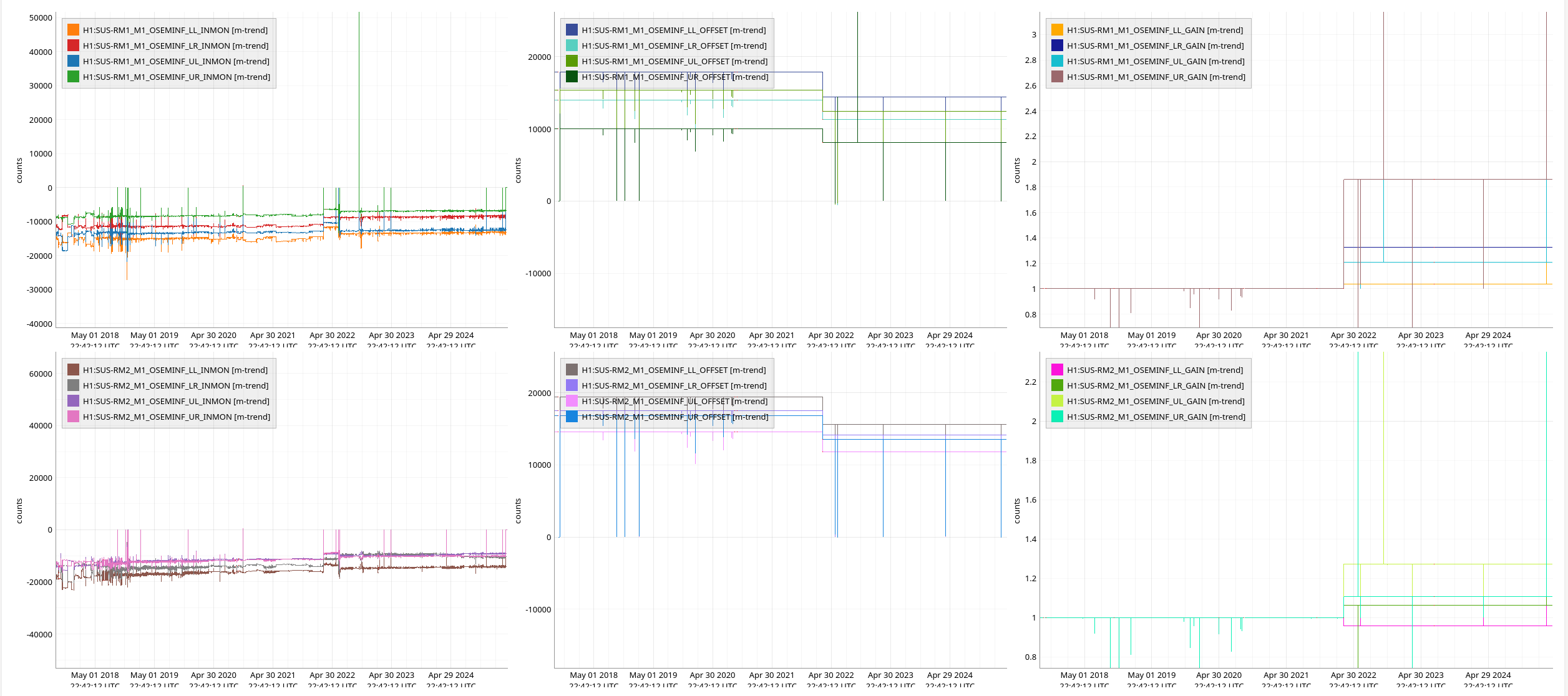
If the Sat Amp PDs are connected as shown om D080276, the OSEM values will be negative. Indeed, the RMs had negative OSEM values as expected. However, all ZMs have positive values, since nobody bothered to flip the pins. We propose to no longer flip the PD pins for the RMs and work with positive OSEM values in the future.

Comments related to this report
jeffrey.kissel@LIGO.ORG - 15:52, Tuesday 29 April 2025 (84176)CDS, ISC, SUS, SYS
J. Kissel

First, supporting Daniel's findings that the RM1 and RM2 HTTS OSEM sensor readbacks have been incorrectly negative for ages, I attach a trend of the OSEM ADC input values (and OSEMINF OFFSETS and GAINs) back to 2017.

Not said explicitly in the above aLOG -- Daniel / Fil / Marc installed fresh new DB25 Sat Amp to Vac Feedthru cables (D2100464) just after this aLOG as a part of cabling up the new signal chain for PM1. These cables are one-to-one pin-for-pin cables so it *should* have played no role in the sign of the sensors or how they're connected. 

However, it's now obvious that RM1 and RM2 have had the ADC input voltages as negative for a *very* long time. 

I reviewed the signal chains for the OSEM PDs; see G2500980.

The RMs are using a US 8CH satamps D1002818 / D080276.

I attach a screen-cap of page 4, which highlights that 
    - UK 4CH satamps D0900900 / D0901284 use 
        . a negative reverse bias configuration, with
        . anode connected to bias and cathode connected to the negative input of the TIA, and
        . an inverting differential amplifier stage
    - US 8CH satamps D1002818 / D080276 use 
        . a positive reverse bias configuration, with 
        . cathode connected to the bias and anode connected to the negative input of the TIA, and [hence the apparent "pin-flip" from the other two satamp types]
        . a non-inverting differential amplifier stage
    - US 4CH satamps D1900089 / D1900217use 
        . a negative reverse bias configuration, with
        . cathode connected to the bias and anode connected to the negative input of the TIA, and
        . a non-inverting differential amplifier stage [hence the overall "sign flip" from the other two]

I disagree with Daniel that "the polarity of the PD" i.e. how the anode and cathode are connected to the transimpedance amplifier.
All versions of the PD pinout + SatAmp configure the system in a reverse bias, be it negative or positive. 
In these configurations, even in a zero bias configuration, photocurrent always flows from from cathode to anode as light impinges on the PD. 
So if the anode is hooked up to the negative input of the transimpedance amp (as in D1002818), that signal will have a different sign than if the cathode is hooked up to the negative input (as in D0900900 and D1900089).

The RMs should have their *positive* bias from the D080276 circuit applied.
In 2011, we'd agreed in G1100856 to jumper all OSEM satamps to the "L" position, a.k.a. the LIGO OSEM a.k.a. AOSEM position, which uses a bias voltage and is thus in photo conductive or pc mode. This is mostly because we wanted to not have to think about keeping track of which satamps are jumpered and which are not, but also because the BOSEM PD didn't mind have a bias, even though it was designed to have no bias.

Given the "thought of 2nd to last, last, and never" history of the RMs as they traversed subsystem from ISC to SUS circa O1, moving from the ASC front-end to a SUS front-end circa O2, then never really appearing in wiring diagrams until O3, etc. it wouldn't surprise me if the RMs didn't get the memo to put the bias jumper in the "L" position jumpering pins 2 and 3.

I disagree with Daniel: only the US 4CH satamp D1900089 / D1900217 should read negative with light on it.

So, my guess is that that someone "in 2013" (i.e. during aLIGO install prior to O1) didn't understand these subtleties between the UK 4CH and US 8CH satamp, saw the "different from UK 4CH satamp" and tried fixing the pins of the in-air D25 from satamp to vacuum flange.

Regardless, the new cable has cleared up the issue, and ADC voltage from RM1 and RM2 is now positive.
Images attached to this comment