Jennie Wright, Sheila, Keita, Camilla
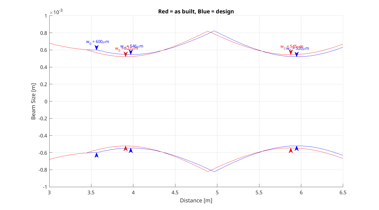
Jennie has been working on modeling of our arm to OMC mode matching, and while she was looking for some distances we noticed a discrepancy between the as built numbers and the mode matching design. It seems possible that there was a mix up, where design documents call for a distance of 97cm between the OMC waist and OM2, and the as built distance is 97 cm between the OMC input coupler and OM2 (so, the OMC seems to be translated by 14 cm from where the mode matching design expected it to be). If we have the q parameter used in the design (ROC matched to SRM, beam size there is 2.1mm), this would introduce a 1% mismatch between the OMC mode and the SRC mode (the impact could be larger for a different q parameter). Note that the analysis done in 71145 was using the design distances, so we will want to revisit that. I've attached an a la mode script below.
Editing to add more information:
I initially did this with the design ROC for OM2, which is 1.7meters, which is also what is in Finesse. This results in an overlap for the design locations of 99.95% and 99% for the as built locations, with the as built waist location 12cm from the OMC waist location (there are differences in the other distances that partially cancel the 14cm difference between OMC input coupler and OMC waist location), and a waist size of 545um compared to the OMC eigenmode of 509um. In 71145 Keita says that the OM2 ROC is 2m cold and 1.75m hot.
If we change the OM2 curvature for the as built path to 2 meters, the overlap becomes 93.8%, and the waist location becomes 14.3cm from the OMC waist location, with a waist size of 649um. Using the hot ROC of 1.75m, the overlap becomes 98.5% and the waist is 563um 11.5cm from the OMC waist. So, if our q parameter was the design one at SRM, the error in OM2 curvature would be compounding the error in the OMC placement to make the mode matching worse. The single bounce measurements agree that the mode matching is worse with OM2 cold than hot, but the full IFO measurements are the opposite.
Summarizing distances:
- OMC waist to OM3: 26.8 cm
- OMC waist to OM2: 97.6 cm
- OMC waist to OM1: 2.37 m
- OMC waist to SRM: 6.017 m
T1200410 says we should have:
- OMC waist to OM3: 26.2cm
- OMC waist to OM2: 97 cm
- OMC waist to OM1: 2.365 m
- OMC waist to SRM: 5.936 m
.yaml file, which is based on E2100383:
- OMC input coupler to OM3: 30.4cm
- OMC input coupler to OM2: 97.1cm
- OMC input coupler to OM1: 2.416m
- OMC input coupler to SRM: 5.858 m
Camilla looking at edrawings (which agree with photos):
- OMC input coupler to OM3: 30.1cm
- OMC input coupler to OM2 95.5cm
- OMC input coupler to OM1: 2.4meters
To compare the solid works to the photos we looked at D0901822 and compared it to OM3 photo and this photo of OM2 when it was a tip tilt.
Using the beam q from table 1 of T1200410 for just after SRM, and propagating it through the distances from T1000317, gives an overlap with the OMC waist of 99.96%. Adjusting the SRM to OM1 distance to agree with T1200410 gives 99.95%, so that difference between the two design documents isn't significant.

Here's a version of the script that I used to make the plot above. a la mode is a matlab beam propagation and mode matching code written by Nic Smith that is available here. If you download that in the control room it will give some errors, I have a copy of the directory I use in matlab2019a in the control room here