J. Freed
Last week, this week, and the next week, the goal is to finalize the double mixer design, drawings and chassis. M. Pirello. has begun the drawings while I finalize the design, and we will work on the layout as well as the front plate.
Currently 83439 shows that phase noise is good except for harmonics every 4096Hz away from carrier. While any frequency more than 100Hz around the carrier should not affect SPI some of them do have an effect (namely the 8192Hz harmonic), 81593 also shows an ocsiloscope reading of the output which shows how messy the signal looks. This as such this week the focus is on reducing those harmonics.
The Q2 transistor on the Low Noise Power Board failed last week, was replaced, then it popped and replaced again. The problem was diagnosed to be the power pins on the ZFL-500HLNB+ amp. The pins stick out and touched the metal casing of another minicircuit part causing a short on the +15V supply from the low noise power board. A temporary solution of electrical tape was use to isolate the pins while a more perminate isolation for the pins will be there when it is finalized
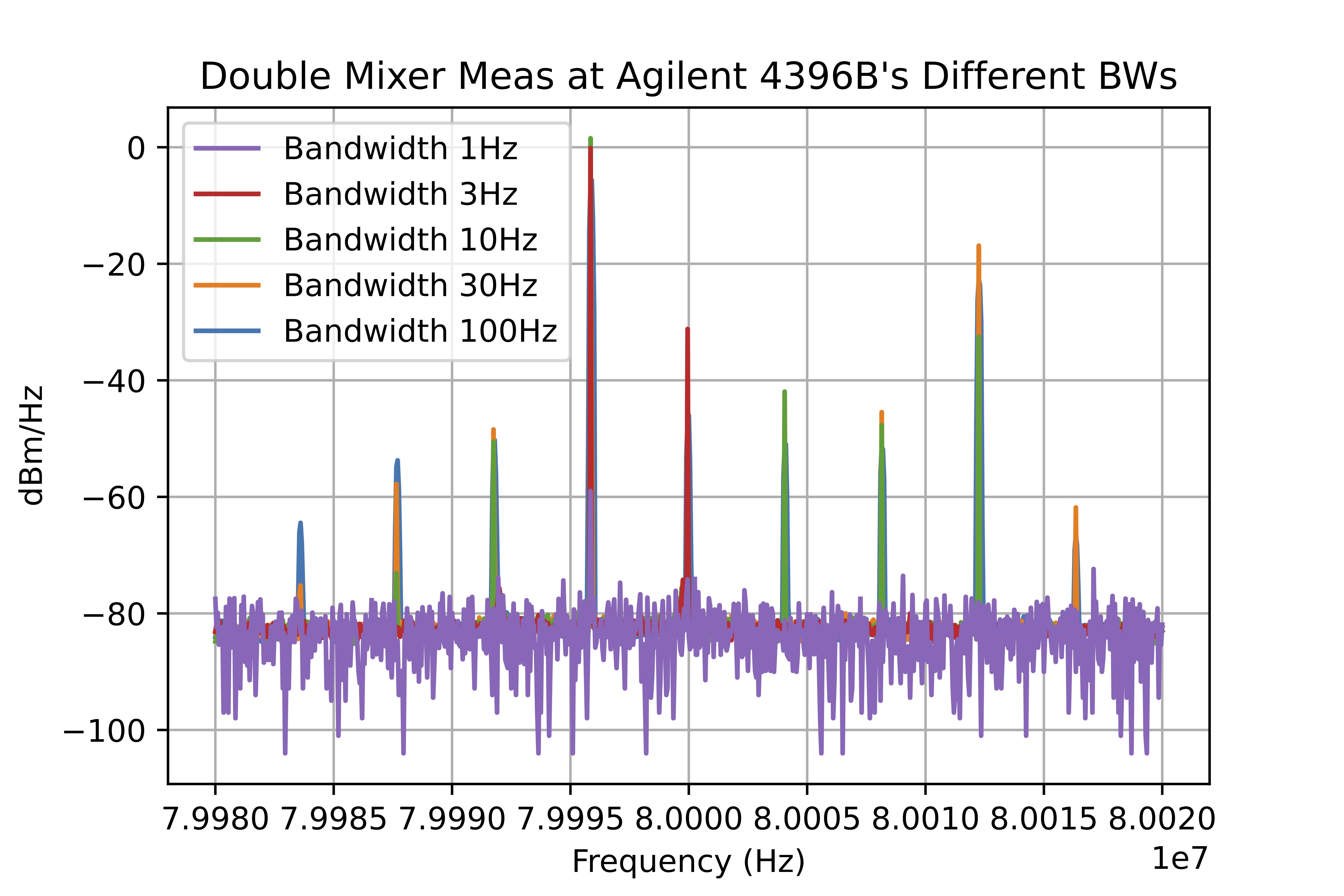
AGBW.jpg Shows that the Agilent 4396B in spectrum analyzer mode gives less information with a smaller resolution bandwidth. The higher resolution bandwidth shows more harmonics with greater power on said harmonics. I do not know why this is, which is why I will be looking at phase noise when trying to improve harmonics.
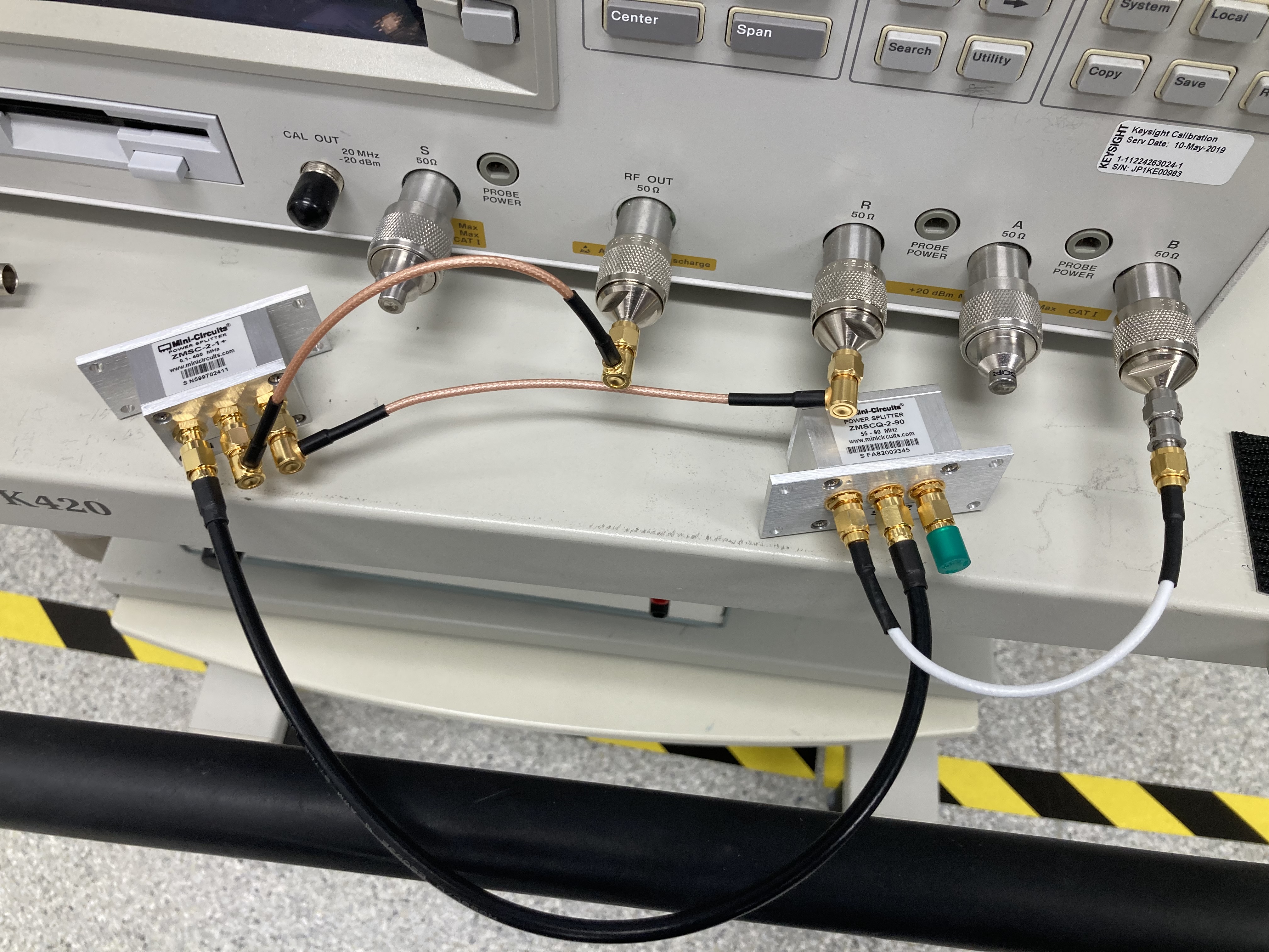
The Agilent 4396B in network analyzer mode was used to take transfer functions of the double mixer phase delayer, IMG_1472.jpg shows the set up. The source power was 13dBm, the central frequency was 80MHz. The Span and Resolution Bandwidth were both 40kHz but changeing these values did not change much as the amplitude and phase was relativly flat around 80 MHz. A 10dB attinuator was added to the output to remove the overload message on port B that appered around 7dBm input power when I was incresing power to 13dBm.This is ok as I could calibrate the machine by replacing the phase delayer with a addaptor that let the signal go straight through. This calibration became my (0dBm 0deg) reference. I took measuments of one port of the phase delayer at a time while terminating the other.
| Gain (dB) +- 0.01 | Phase (deg) +- 0.1 | |
| Port 1 | -3.31 | -84.6 |
| Port 2 | -2.93 | 3.1 |
| Difference | 0.38 | -87.7 |
This is slightly off from what was hoped for with (0dBm -90deg) difference. SPI has some 0.5dB attinuators as well as 1dB attinuators. Due to the attinuators not being their listed value at 80 MHz, Two 0.5dB attinuators on port 2 and one 1dB attinuator on port 1 seems to nearly correct the power differnece.
Continuing from here is characterizing the mixers, the summer, and RF couplers to gain inisight on reducing the harmonics.