Edgard, Oli.
Follow up to the work summarized in 84012 and 84041.
TL;DR: Oli tested the estimator on Friday and found the ISI state affects the stability of the scheme, plus a gain error in my fits from 84041. The two issues were corrected and the intended estimator drives look normal (promising, even) now. The official test will happen later, depending on HAM1 suspension work.
____
Oli tested the OSEM estimator damping on SR3 on Friday and immediately found two issues to debug:
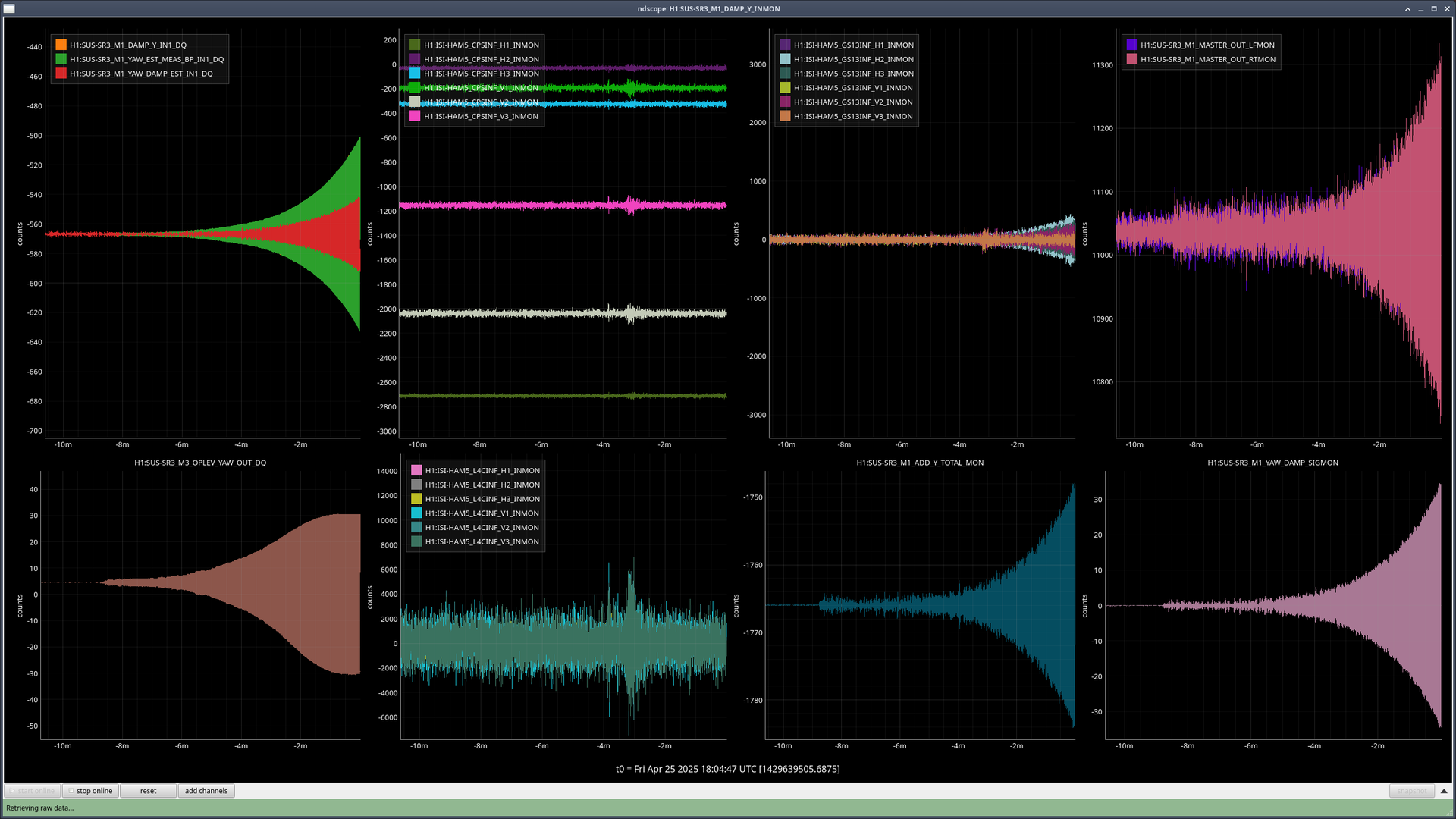
1) [See first attachment] The ISI state for the first test that Oli ran was DAMPED. Since the estimator was created with the ISI in ISOLATED (and it is intended to be used in that state), the system went unstable. This issue is exacerbated by point 2) below. This means that we need to properly manage the interaction of the estimator with guardian and any watchdogs to ensure the estimator is never engaged if the ISI trips.
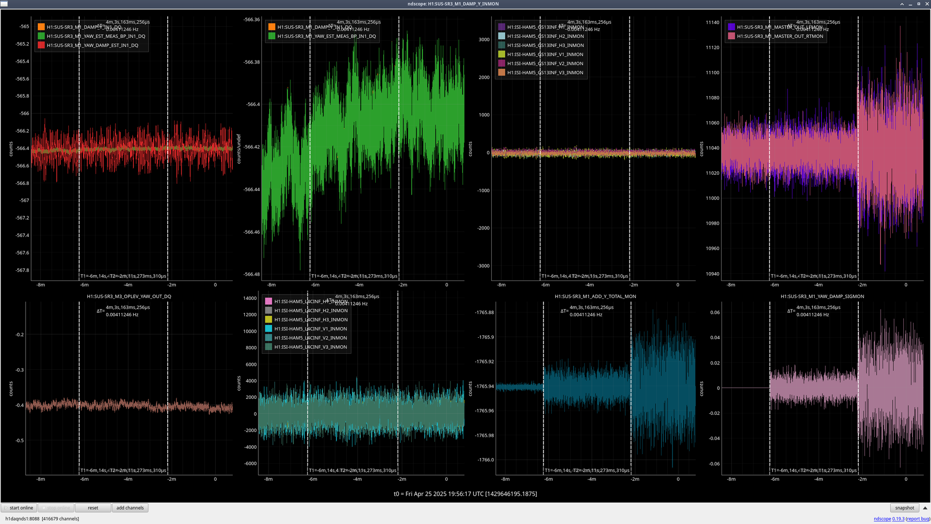
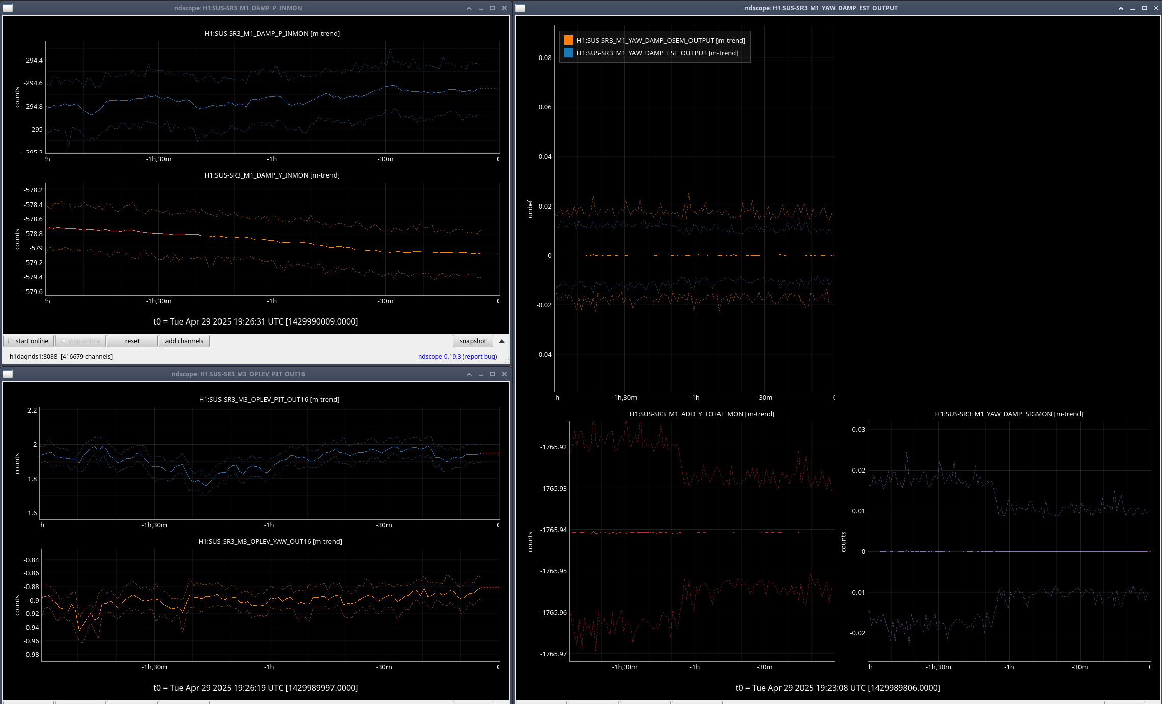
2) [See second attachment] There was a miscalibration of the fits I originally imported to the front-end. This resulted in large drives when using the estimator path. In the second figure, there are three conditions for the yaw damping of SR3:
( t < -6 min ) OSEM damping with gain of -0.1.
( -6 min< t < -2 min) OSEM damping with a gain of -0.5, split between the usual damping path and the estimator path.
( -2 min < t < 0 min) OSEM + Estimator damping.
The top left corner plot shows the observed motion from every path. It can be seen that M1_YAW_DAMP_EST_IN1 (the input to the estimator damping filters) is orders of magnitude larger than M1_DAMP_IN1 (the imput to the regular OSEM damping filters).
The issue was that I fit and exported the transfer functions in SI units, [m/m] for the suspoint to M1, and [m/N] for M1 to M1. I didn't export the calibration factors to convert to [um/nm] and [um/drive_cts], respectively.
____
I fixed this issue on Friday. Updated the files in /sus/trunk/HLTS/Common/FilterDesign/Estimator/ to add a calibration filter module to the two estimator paths (a factor of 0.001 for suspoint to M1, and 1.5404 for M1 to M1). The changes are current as of revision 12288 of the sus svn.
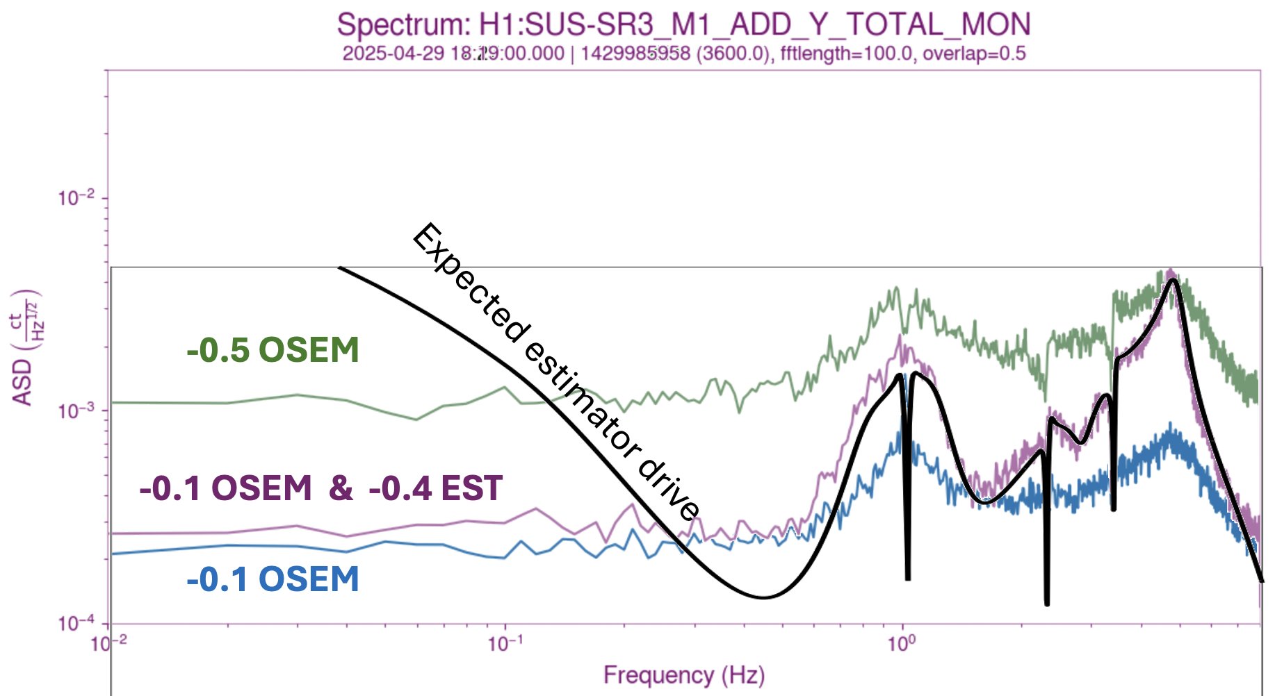
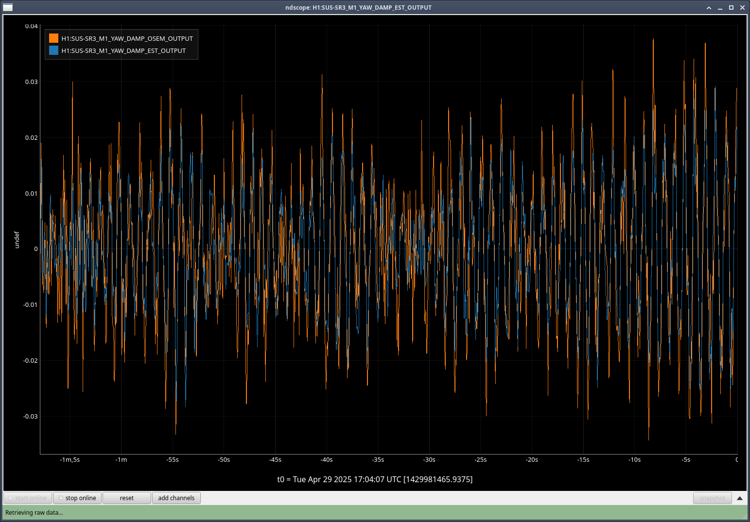
The third attachment shows the intended drives from the estimator and OSEM-only paths. They look similar enough that we believe the miscalibration issue has been resolved. For now we stand by until there is a chance to test the scheme again.
I've finished the set of test measurements for this latest set of filter files (where we now have the calibration filters in)
These tests were done with HAM5 in ISOLATED
Test 1: Baseline; classic damping w/ gain of Y to -0.1(I took this measurement after the other two tests)
start: 04/29/2025 19:22:05 UTC
end: 04/29/2025 20:31:00 UTC
Test 2: Classic damping w/ gain of Y to -0.1, OSEM Damp Y -0.4
start: 04/29/2025 17:16:00 UTC
end: 04/29/2025 18:18:00 UTC
Test 3: Classic damping w/ gain of Y to -0.1, EST Damp Y -0.4
start: 04/29/2025 18:18:05 UTC
end: 04/29/2025 19:22:00 UTC
Now that we have the calibration in, it looks like there is a decrease in the noise seen between damping with the osems vs using the estimator.
In the plot I've attached, the first half shows Test 2 and the second half shows Test 3
I analyzed the output of the tests for us to compare.
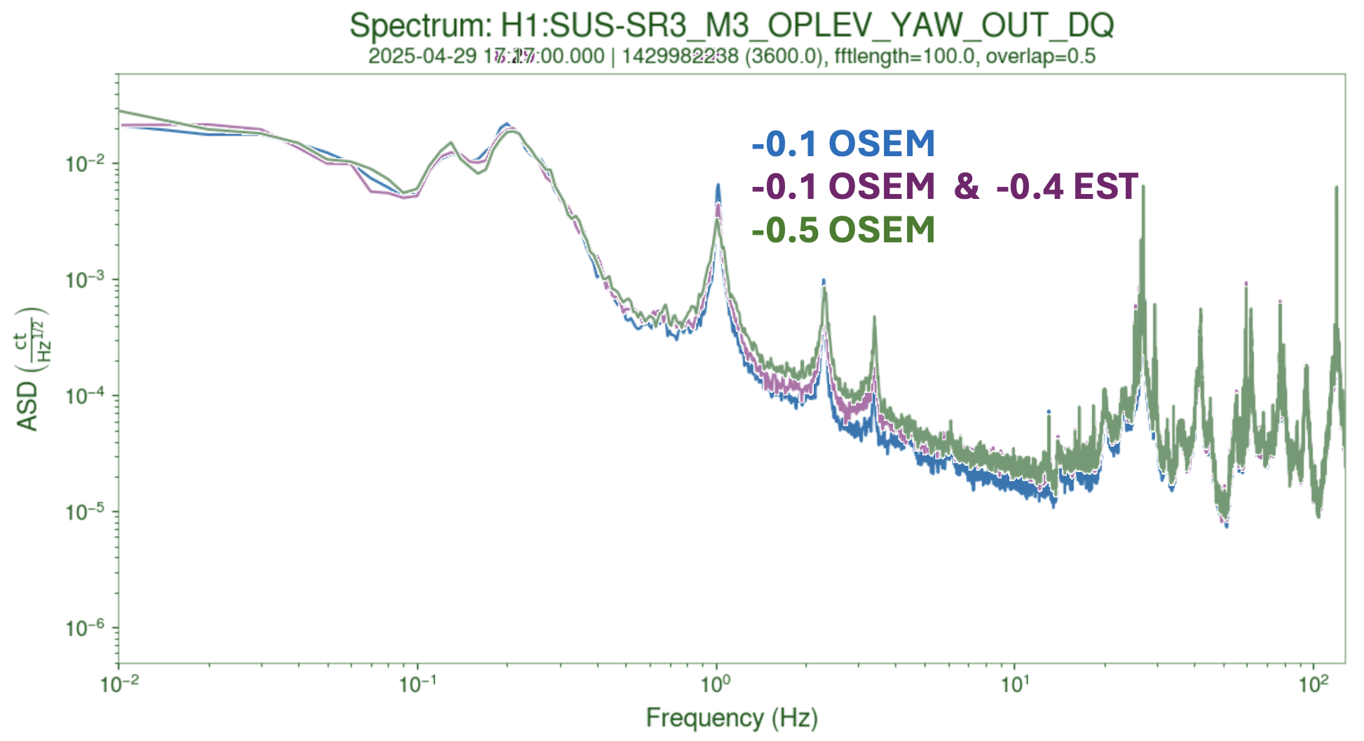
1) First attachment shows the damping of the Yaw modes as seen by the optical lever in SR3. We can see that the estimator is reducing the motion of the 2 Hz and 3 Hz frequency modes. This is most easily seen by flicking through pages 8-10 of the .pdf attached. The first mode's Q factor is higher than OSEM only damping at -0.5 gain, but it is lower than if we kept a -0.1 gain.
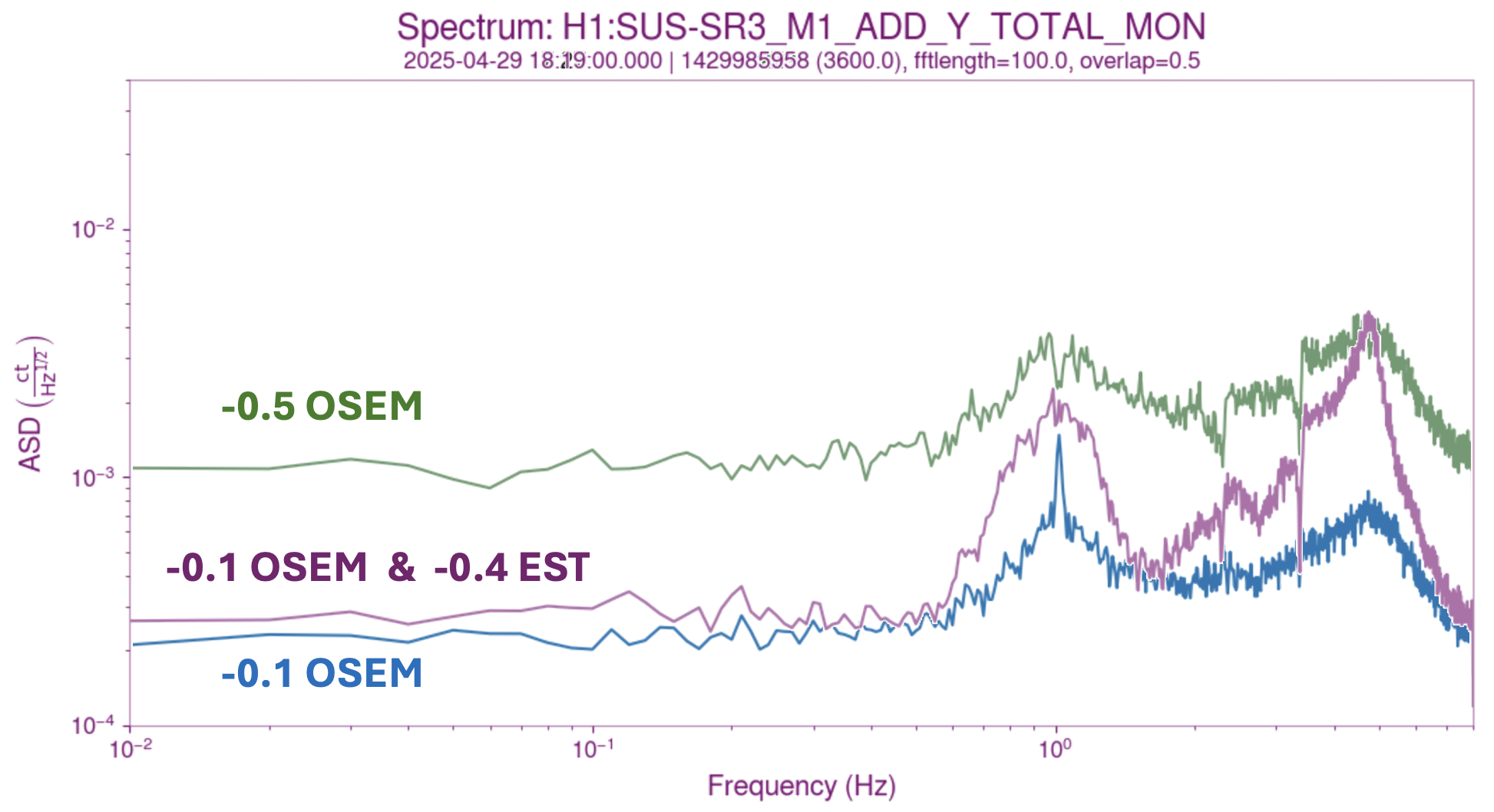
2) The second attachment shows that we get this by adding less noise at higher frequencies. From 5 Hz onwards, we have less drive going to the M1 Yaw actuators, which is a good sign. There is a weird bump around 5 Hz that I cannot explain. It could be an artifact of the complementary filters that I'm not understanding, or it could be an artifact of using a 16Hz channel to observe these transfer functions.
Considering that the fits were made on Friday while the chamber was being evacuated and that the suspension had not thermalized, I think this is a success. The Optical lever is seeing less motion in the 1-5 Hz band consistent with expectations (see, for example some of the error plots in 84004), with the exception of the 1Hz resonance. We expect this error to be mitigated by performing a fit with the suspension thermalized.
Some things of note:
- We could perform an "active" measurement of the estimator's performance by driving the ISI during the next round of measurements. We don't even have to use it in loop, just observe M1_YAW_EST_DAMP_IN1_DQ, and compare it with M1_DAMP_IN1_DQ.
The benefit would be to get a measurement of the 'goodness of fit' that we can use as part of a noise budget.
- We should investigate the 5 Hz 'bump' in the drive. While the total drive does not exceed the value for OSEM-only damping, I want to rule out the presence of any weird poles or zeros that could interact negatively with other loops.

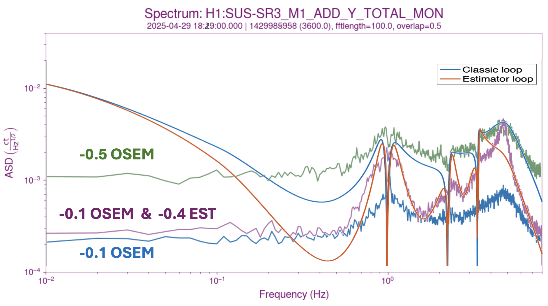
Attached you can see a comparison between predicted and measured drives for two of the conditions of this test. The theoretical predictions are entirely made using the MATLAB model for the suspension and assume that the OSEM noise is the main contributor to the drive spectrum. Therefore, they are hand-fit to the correct scale, and they might miss effects related to the gain miscalibration of the SR3 OSEMs shown in the fit in 84041 [note that the gain of the ISI to M1 transfer function asymptotes to 0.75 OSEM m/ GS13 m, as opposed to 1 m/m].
In the figure we can see that the theoretical prediction for the OSEM-only damping (with a gain of -0.5) is fairly accurate at predicting the observed drive for this condition. The observed feature at 5 Hz is related to the shape of the controller, which is well captured by our model for the normal M1 damping loops (classic loop).
In the same figure, we can see that the expected estimator drive is similarly well captured (at least in shape) by the theoretical prediction. Unfortunately, we predict the controller-related peaking to be at 4 Hz instead of the observed 5 Hz. Brian and I are wary that it could mean we are sensitive to small changes in the plant. The leading hypothesis right now is that it is related to the phase loss we have in the M1 to M1 transfer function that is not captured by the model.
The next step is to test this hypothesis by using a semi-empirical model instead of a fully theoretical one.
We were able to explain the drive observed in the tests after accounting for two differences not included in the modelling:
1) The gain of the damping loop loaded into Foton is different from the most recent ones documented in the sus SVN:
sus/trunk/HLTS/Common/FilterDesign/MatFiles/dampingfilters_HLTS_H1SR3_20bitDACs_H1HAM5ISI_nosqrtLever_2022-10-31.mat
They differ by a factor of 28 or so, which does not seem consistent with a calibration error of any sort. But since it is not documented into the .mat files makes it difficult to analyze without ourtright having the filters currently in foton.
2) There was spurious factor of 12.3 on the measured M1 to M1 transfer function due to gains in the SR3_M1_TEST filter bank ( documented in 84259 ). This factor means that our SR3 M1 to M1 fit was wrong by the same factor, the real transfer function is 12 times smaller than the measured one, and in turn, than our fit.
After we account for those two erroneous factors, our expected drive matches the observed drive [see attached figure]. The low frequency discrepancy is entirely because we overestimate the OSEM sensor noise at low frequencies [see G2002065 for an HSTS example of the same thing]. Therefore, we have succeeded at modelling the observed drives, and can move on to trying the estimator for real.
_____
Next steps:
- Recalibrate the SR3 OSEMs (remembering to compensate the gain of the M1_DAMP and the estimator damping loops)
- Remeasure the ISI and M1 Yaw to M1 Yaw transfer functions
- Fit and try the estimator for real