Jennie W, Sheila,
I have been working on a numerical model to check against some of our single bounce and full IFO measurements of the OMC to IFO mode-matching. Keita did a similar analysis using single bounce measurements and an alamode mode-matching simulation here alog #71145. In this entry while trying to check input parameters for the model, Sheila, Keita, Camilla and I worked out that the original; design for the OMC telescope has an extra 14 cm between OM1 and the input to the OMC.
My model takes the parameters for the bow-tie OMC cavity design from LIGO-T1300189, page six.
distance between two flat mirrors = distance between two curved mirrors = 0.2816m
diagonal distance between one curved and one flat mirror = 0.2844m
The RoC for each curved mirrors is take from LIGO-T1500060
Mirror C6 in table in appendices is curved mirror 1 in OMC design.
RoC CM1 = 2.57321 m
Mirror C5 is CM2
RoC CM2 = 2.57369 m.
Using the ABCD matrices for each mirror and the spaces between them I solved for the q parameter of the circulating mode just inside the input coupler.
This is q = -0.1408 + 0.7102i m.
This gives a beam waist between the two flat mirrors of 4.9044e-4 m. Note: The following analysis is all for the vertical modes, since the OMC has some astigmatism due to a non-zero angle of incidence in the horizontal direction we simplify our analysis by only considering the vertical modes in the mode propagation, this is especially easy for our particular OMC (OMC001) as it has a very small degree of astigmatism (108 kHz difference vs the fwhm of the resonance at 667 kHz) between the vertical and horizontal modes.
I then start just in front of OM2 using a q parameter (q_pre_OM2 = 0.8902 + 0.8034j) Sheila worked out from propagating the q from table 1 of LIGO-T1200410 for just after SRM using her alamode model from (alog #84089) entry.
I construct some 70 x 70 grid of possible q parameters.
I then propagate this towards the OMC using both the hot (1.75m RoC) and cold (2.1m RoC) that OM2 can have in its two PSAMS states (for calibration of the heater see alog #65276 and for the radii of curvature see alog #71145).
The q parameter can be used to define the electric field amplitude transverse to the beam propagation direction z:
U = 1/q ( exp( -jk ( x2 + y2 ) / 2q ))
where k is the wavenumber of the light and x and y are the transverse distances from the center of the beam in the horizontal and vertical directions.
Using the overlap integral:
O(q1,q2) = | U2 U1* |2 / ( |U1|2 |U1|2 )
where U1 is the field amplitude for TM 00 mode of the OMC and U2 is the field amplitude of the pre-OM2 mode after propagation to the OMC.
for the OMC field and each of the fields propagated from before OM2 I work out two mode mis-match plots, where mode-mismatch (MM) is:
MM % = (1 - O(q1,q2)) * 100,
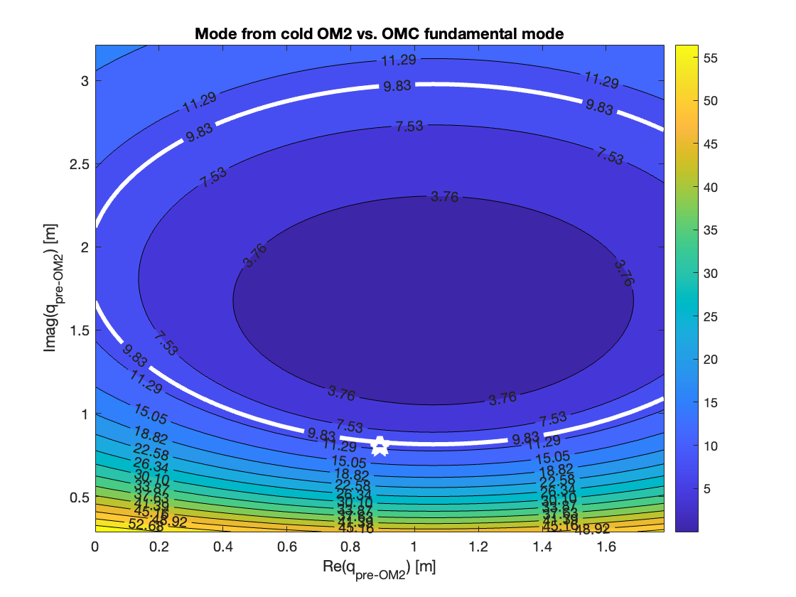
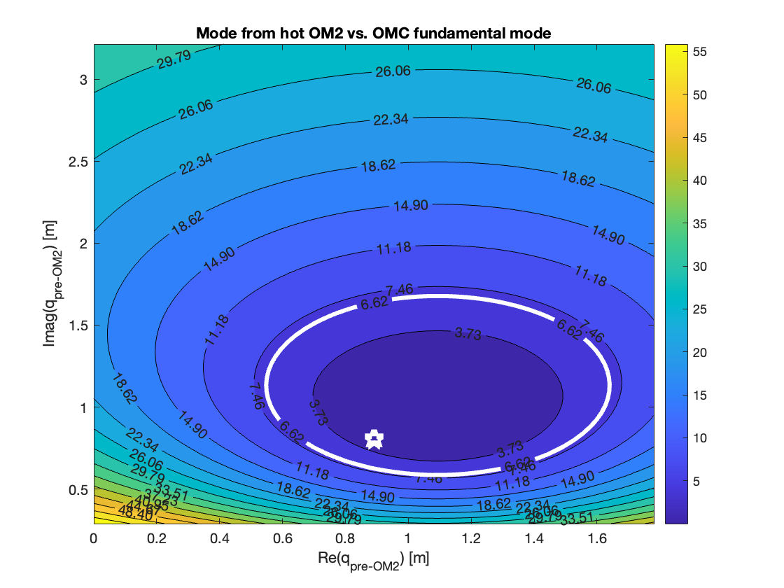
in terms of the imaginary and real parts of the q parameter I started with upstream of OM2. See image 1 for the grid of pre-OM2 modes against the mis-match each mode would have with the OMC mode at the OMC after propagating through a cold OM2 and OM3. See image 2 for the same plot but with the mis-match the pre-OM2 grid would have after propagating through a hot OM2 and OM3.
On both images the original mode before OM2 is shown by a white star and the coloured countours show the mode-mis-match percentage at the OMC. The white contour in each plot is a measurement of the single bounce mode-mismatch measured in alog #79229 for the cold state and in alog #78727 for the hot state.
Sheila verified these mode-matching values for the hot and cold state of OM2 by propagating q_pre_OM2 in her model to the OMC and overlapping it with the OMC q parameter from my model.
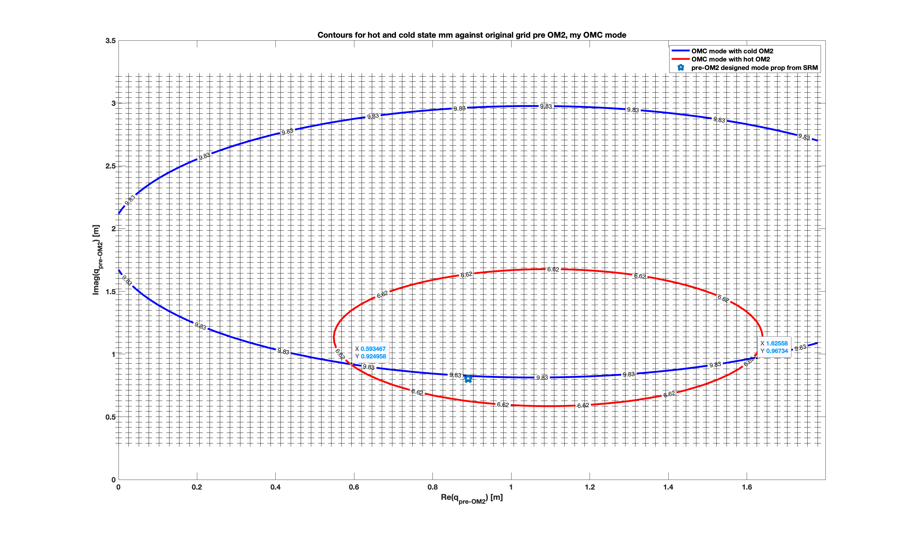
The points where the two measurement contours overlap give us two possible q parameters for the real mode pre-OM2 in the single bounce state. See the third image, where the blue contour is the mode-mismatch measured with the OM2 in the cold state and the red contour that measured with the OM2 in the hot state. The light blude star is the pre-OM2 q used in my numerical model obtained from Sheila's alamode model.
The two possible qs that match experiment are q1 = 0.593 + 0.925j and q2 = 1.626 + 0.967j. This gives a beamwaist of 5.597e-4 m located 0.681 m behind OM2 or a beamwaist of 5.722e-4m located 1.714m behind OM2.
Terra Hardwick and others did some on-bench beam profiler measurements in HAM6 (alog #41490) and their model for between OM1 and OM2 seems to be consistent with q1 rather than q2.

The OMC waist used in the orginal mode-matching design document for the OM1-OM2-OM3 telescope (LIGO-T1000317) was 5.09e-4 m.
Note the OMC has two waists, one between the two flat mirrors (closer to the input coupler) and a larger waist between the two curved mirrora.
The waist (in the vertical direction) I calculated for the as-built curvatures was 4.9043e-4 m. This was with the flat mirror-flat mirror distance in the OMC as 0.2816 m and the flat mirror-curved mirror diagonal as 0.2844m.
The waist from Zac Korth's measurements (LIGO-D1300507) of our OMC before installation was 4.907e-4 m (vertical waist between two flat mirrors) with the flat-flat distance as 0.2815m and the flat-curved diagonal distance as 28.42m.
Code used to run analysis is at https://git.ligo.org/aligo_commissioning/omc-mode-matching and the main file is OM2_to_OMC_h_c.m. The commit is 50465375.