jeffrey.kissel@LIGO.ORG - posted 13:55, Tuesday 06 May 2025 (84289)
RM1 and RM2 Signs... Again
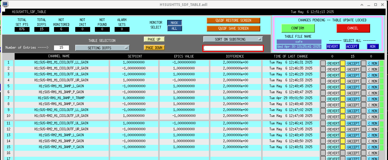
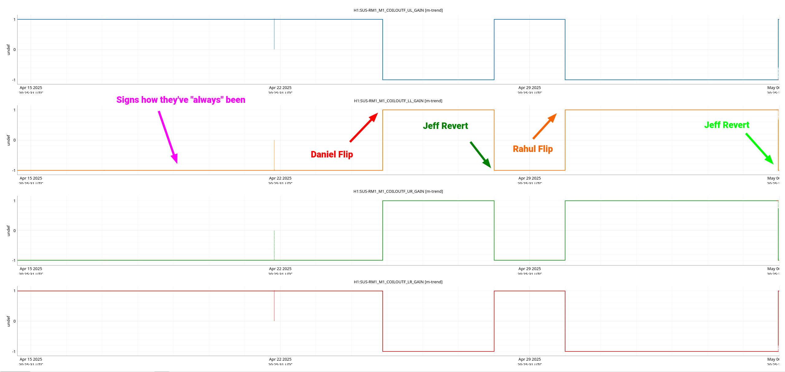
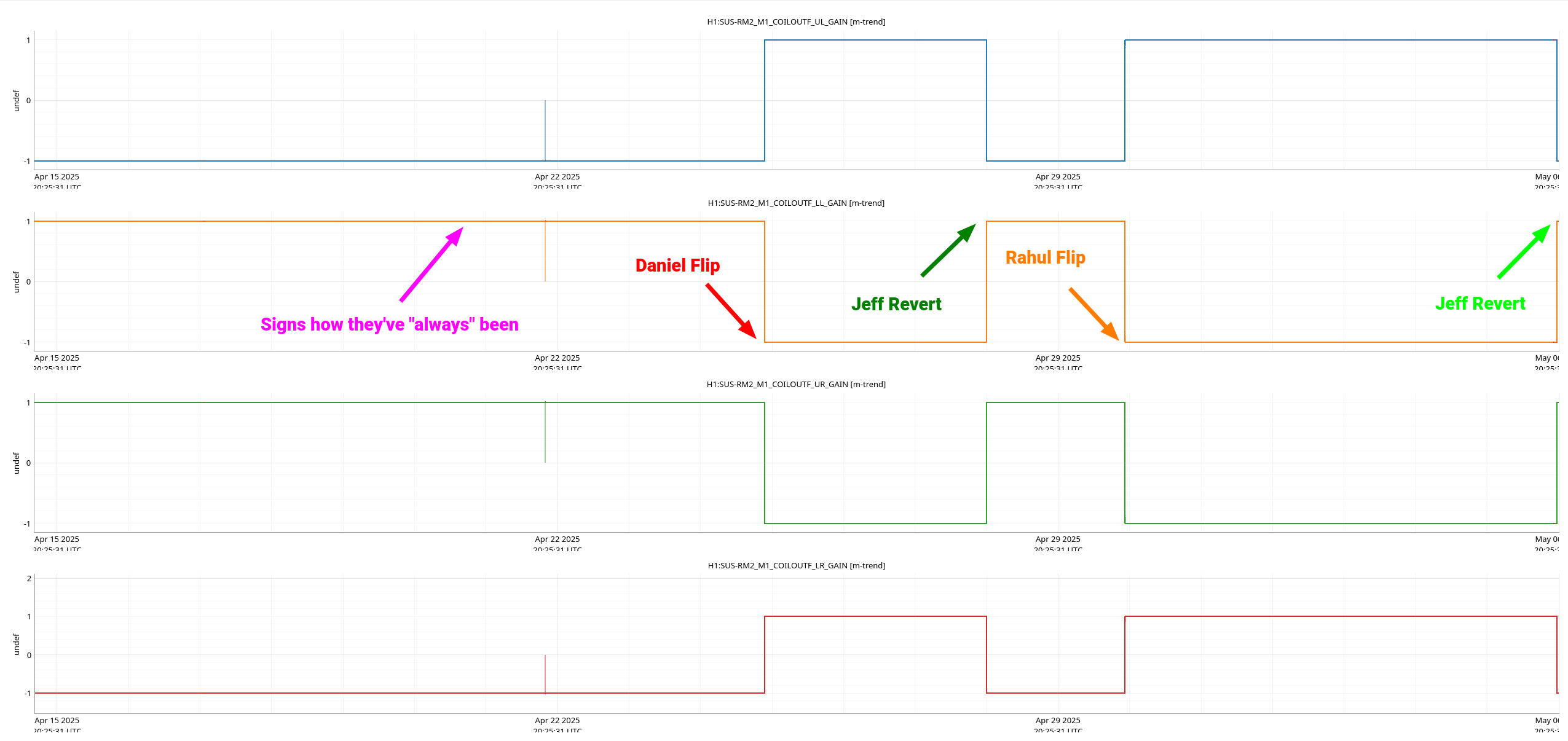
J. Kissel

It was brought to my attention that the DC centering loops for the REFL path weren't working, so we revisited the sign of the RM1 and RM2 signal chains to confirm the functionality.

Recall,
- 2025-04-21 Daniel Fil and Marc found that raw ADC input voltage for OSEM sensor readbacks for the RMs were negative, and have been for over a decade, discovered as they replaced the in-air, sat-amp to vac feedthru cable which flipped the sign for both RM1 and RM2 OSEM sensors. LHO:84027
- 2025-04-25 Daniel, acknowledging that this OSEM sensor sign flip should be accounted for somewhere, decided to stick the sign flip in the 4x COILOUTF gains, typically reserved for magnet polarity compensation. LHO:84123
He acknowledged that putting the compensating sign there would impact the REFL WFS DC centering loops, and we've later realized this will also impact the alignment sliders.
- 2025-04-29 For the above three "don't put the sign flip there!" reasons, on 2025-04-29, I reverted Daniel's COILOUTF gain sign flip. LHO:84186
That means that regardless of whether RM1 or RM2 have the wrong magnet polarity (see LHO:40853 which concluded it was RM2***), the actuator chain's sign will be the same as it has been for a very long time, and no ISC or alignment loops should need adjusting.
I left that aLOG with a "we'll adjust the damping loop signs once the in-chamber work dust settles."
- 2025-04-30 Rahul, a day later, wanted to resolve the remaining issue. I then communicated to Rahul that we needed to flip the sign in the DAMPING loops, and *only* in the DAMPING loops, because these are the only loops that would need to be changed. He instead re-flipped the coil output filter COILOUTF gains again, see LHO:84204, and accepted them into SDF.

So, today, 2025-05-06
I again reverted the sign back to how they've been since 2013
    $ caget H1:SUS-RM1_M1_COILOUTF_UL_GAIN H1:SUS-RM1_M1_COILOUTF_LL_GAIN H1:SUS-RM1_M1_COILOUTF_UR_GAIN H1:SUS-RM1_M1_COILOUTF_LR_GAIN
    H1:SUS-RM1_M1_COILOUTF_UL_GAIN 1
    H1:SUS-RM1_M1_COILOUTF_LL_GAIN -1
    H1:SUS-RM1_M1_COILOUTF_UR_GAIN -1
    H1:SUS-RM1_M1_COILOUTF_LR_GAIN 1

    $ caget H1:SUS-RM2_M1_COILOUTF_UL_GAIN H1:SUS-RM2_M1_COILOUTF_LL_GAIN H1:SUS-RM2_M1_COILOUTF_UR_GAIN H1:SUS-RM2_M1_COILOUTF_LR_GAIN
    H1:SUS-RM2_M1_COILOUTF_UL_GAIN -1
    H1:SUS-RM2_M1_COILOUTF_LL_GAIN 1
    H1:SUS-RM2_M1_COILOUTF_UR_GAIN 1
    H1:SUS-RM2_M1_COILOUTF_LR_GAIN -1

and now have also flipped the damping loop sign, to account for the OSEM sensor readback sign change fixed from the in-air satamp to feedthru change
    $ caget H1:SUS-RM1_M1_DAMP_L_GAIN H1:SUS-RM1_M1_DAMP_P_GAIN H1:SUS-RM1_M1_DAMP_Y_GAIN
    H1:SUS-RM1_M1_DAMP_L_GAIN      1
    H1:SUS-RM1_M1_DAMP_P_GAIN      1
    H1:SUS-RM1_M1_DAMP_Y_GAIN      1
    $ caget H1:SUS-RM2_M1_DAMP_L_GAIN H1:SUS-RM2_M1_DAMP_P_GAIN H1:SUS-RM2_M1_DAMP_Y_GAIN
    H1:SUS-RM2_M1_DAMP_L_GAIN      1
    H1:SUS-RM2_M1_DAMP_P_GAIN      1
    H1:SUS-RM2_M1_DAMP_Y_GAIN      1

This *positive* damping loop gain is markedly different than any other suspension, which have damping loop gains negative. Now I'm pretty confident that means that RM1's magnet polarities have been installed incorrectly, rather than RM2 as declared in 2018 ***.
However, because we tried during this vent and can't access the magnets to verify the polarity, let alone change it (see LHO:84178), we will leave this situation as is because we don't want to have to think about the down-stream impacts of alignment and DC centering.

That being said, the ISC team is going to put a positive digital alignment offset in PIT and YAW now, and will confirm that this steers the beam according to standard SUS convention:
    :: with a right-handed coordinate system defined by +L perpendicular to, and coming out from, the HR surface, and +V pointing up,
    :: +PIT should push the optic "down" curling around the +T access, and
    ::: +YAW should push the optic "counter clockwise, if you're looking from above the mirror, down the -V axis."
If they find this backwards, the may request a change...

For now, in this sign configuration, I've
- Confirmed that the damping loops close and are stable, and
- Saved the current sign state into the userapps repo copy of the h1sushtts_safe.snap, to which the target area's safe.snap and OBSERVE.snap both point,
    /opt/rtcds/lho/h1/target/h1sushtts/h1sushttsepics/burt$ ls -l safe.snap
        lrwxrwxrwx 1 controls advligorts 64 Oct  5  2017 safe.snap -> /opt/rtcds/userapps/release/sus/h1/burtfiles/h1sushtts_safe.snap
    /opt/rtcds/lho/h1/target/h1sushtts/h1sushttsepics/burt$ ls -l OBSERVE.snap
        lrwxrwxrwx 1 controls advligorts 64 Jun 22  2018 OBSERVE.snap -> /opt/rtcds/userapps/release/sus/h1/burtfiles/h1sushtts_safe.snap


Attached are
    - a screenshot of me accepting the correct, above mentioned, COILOUTF and DAMP gains in SDF (I swear and promise I hit accept after I took the shot.)
    - a one-month trend of the RM1 COILOUTF gains, with the above associated timeline called out
    - a one-month trend of the RM2 COILOUTF gains, with the above accociated timeline called out
Images attached to this report