Oli, Keita, Elenna, Jennie, Sheila, Ryan S, Ryan, Jeff, Camilla
Day 1: 84193, Day 2: 84228, Day 3: 84230 and 84239, Day 4: 84274
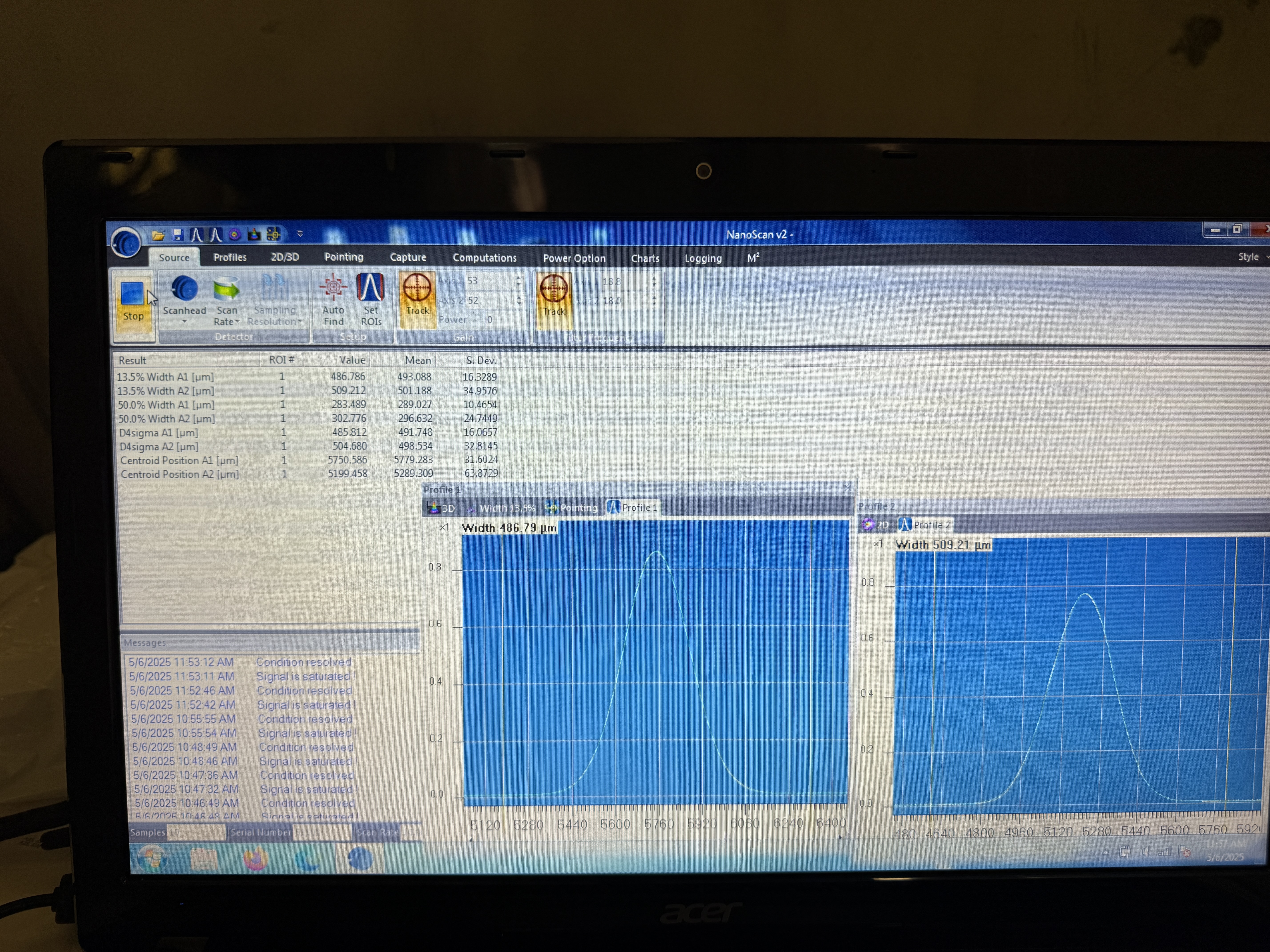
Realsied that yesterday we had the POP aligned causing flashes and need to have ITMX misaligned to work on the REFL path best. Elenna and Keita re-took the final two REFL path beam profile measurements, Travis and I turned down the purge air for these. Turned back up to maxium afterwards.
Rahul installed PM1, slightly out of the way of the POP path so it will need to be moved ~12" to be in it's final postion. It's beam dump will later be added.
Oli, Shiela and I recentered the ASC REFL B diode as yesterday we left it with the beam off mostly off the diode. We swapped the pico cables to the two on sled picos so now the match the medm labels and tested them both. Sheila then centered ASC REFL B using picos. Around 400 NSUM counts on each diode with 200mW of PSL beam in.
Elenna, Sheila and Jeff did some troubleshooting of the DC centering loops (use ASC REFL A and B signals and feedback to RM1 and RM2), there was two issues: one was that the RM1 and RM2 sign flip was no effecting the LOCK filters, Jeff chnegd this (see 84289), secondly it seemed that what was the DC signal of ASC REFL A is now ASC REFL B, Ryan is doing some alog digging to check if this was known in the last HAM1 vent. It's possible the DC signals have just been the wrong way around and this would make some sense why the pico labeled were swapped, but if the RF signals are swapped it will cause lots of issues locking the IFO. After these things were fixed, the DC centering loops were working.
Oli turned up the PSL input to 2W and then de-energized and locked out.
Elenna and I could then see POP flashes, we started to align the periscope but ran out of time before finishing.
ITMX left misaligned so there3's no POP beam.