|
location number on drawing |
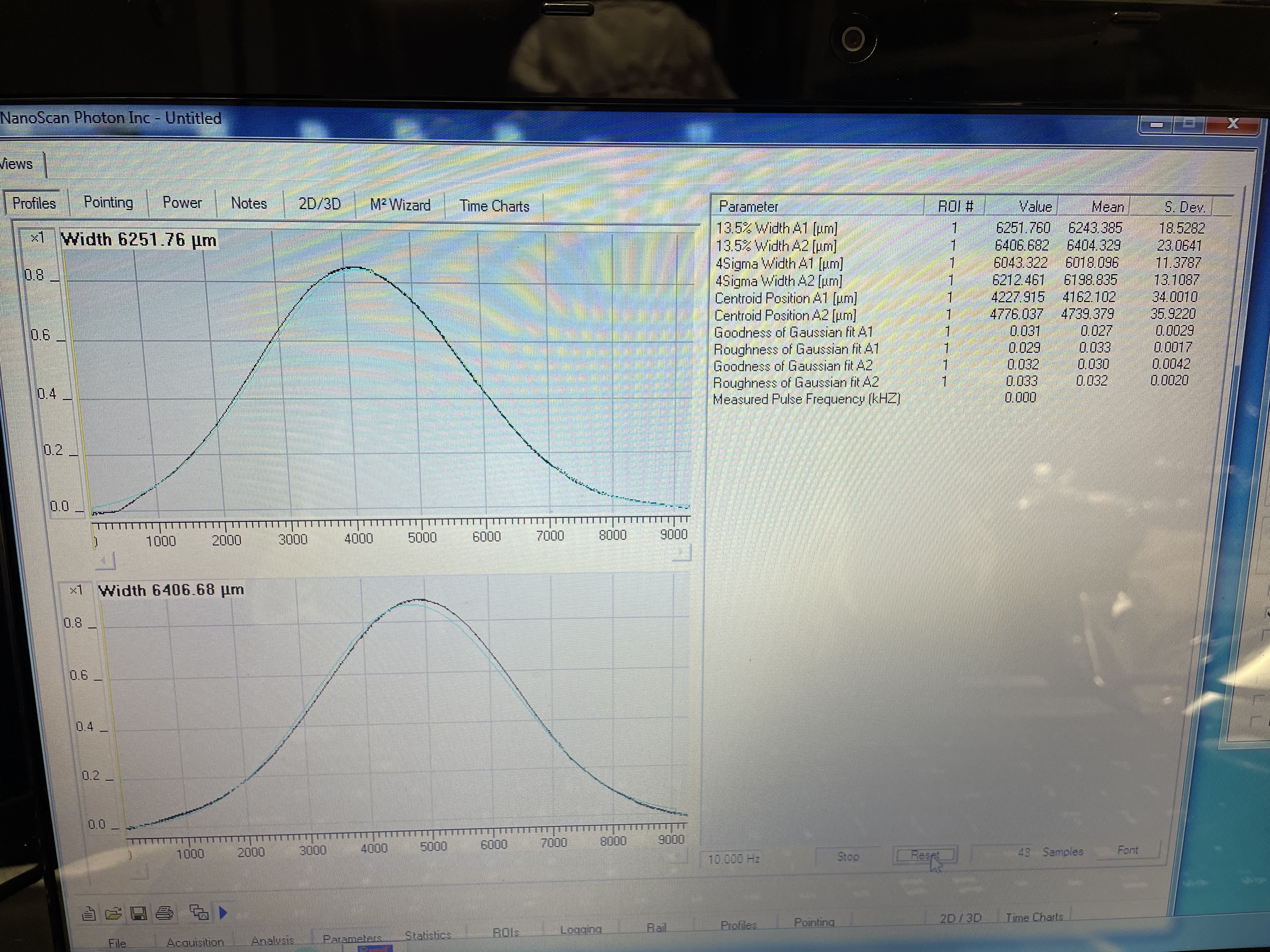
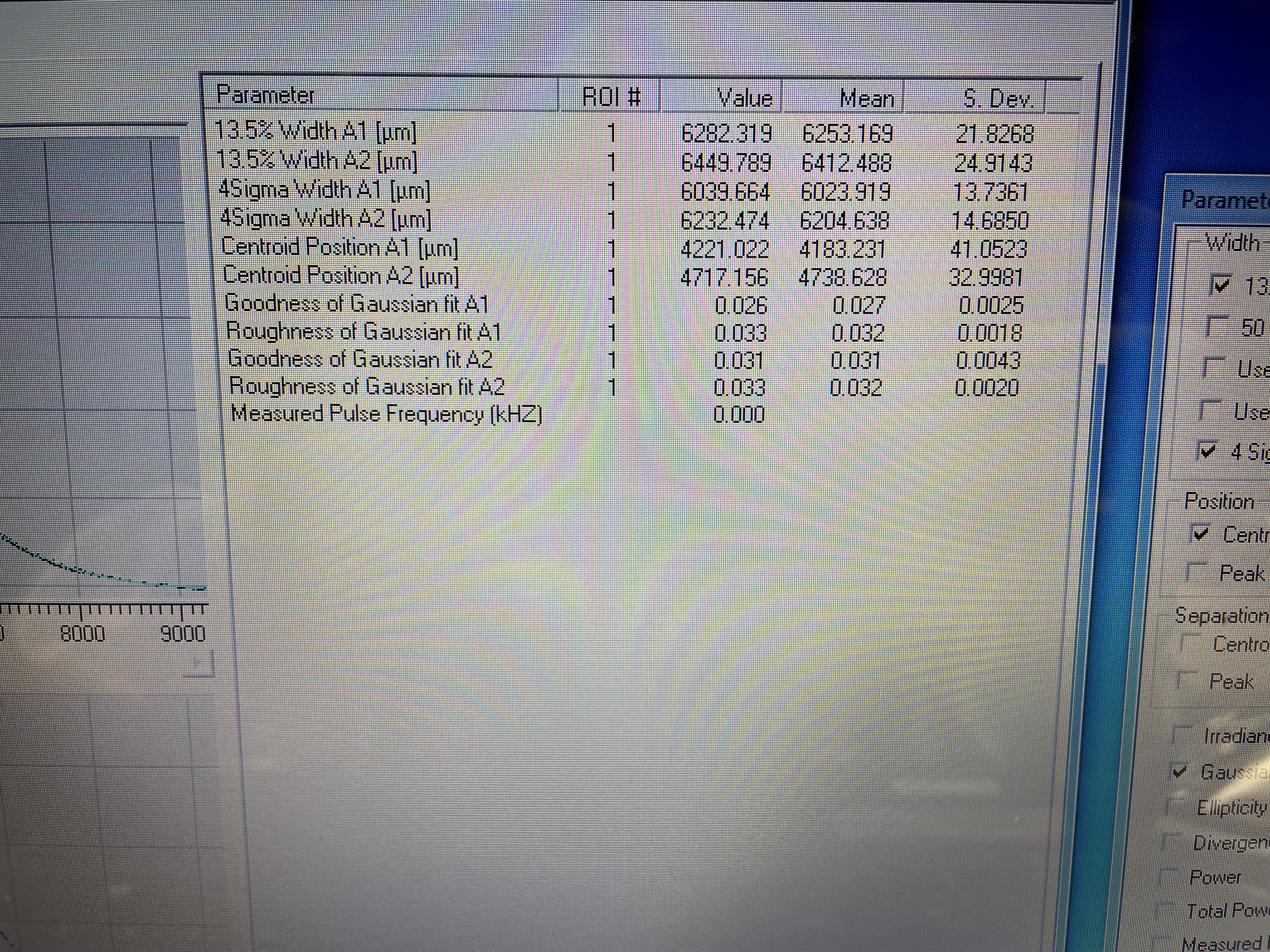
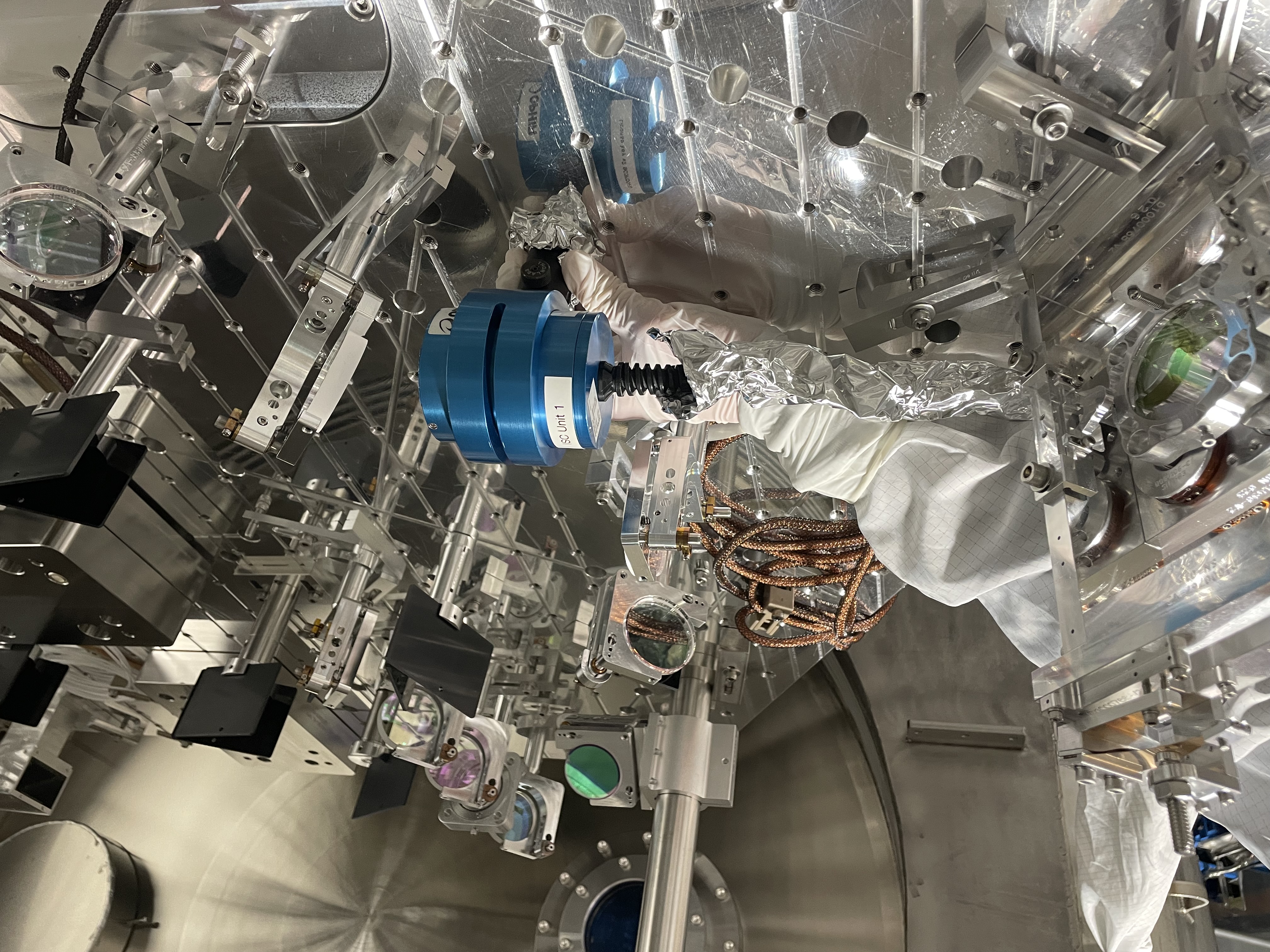
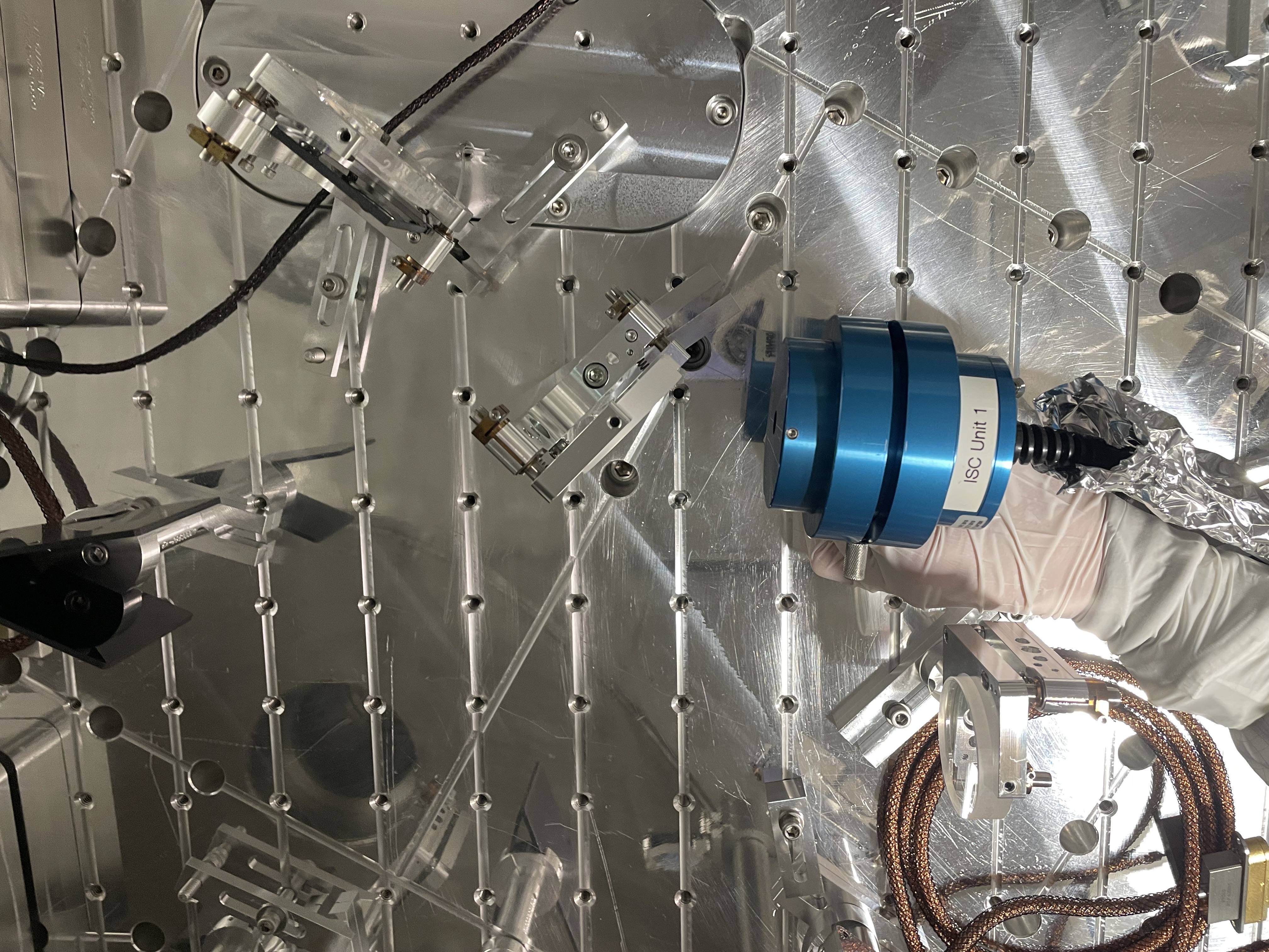
distance | horizontal 13.5% diameter [um] | vertical 13.5% diameter [um] | photo of profiler location | photo of profiles | photo of beam scan measurements |
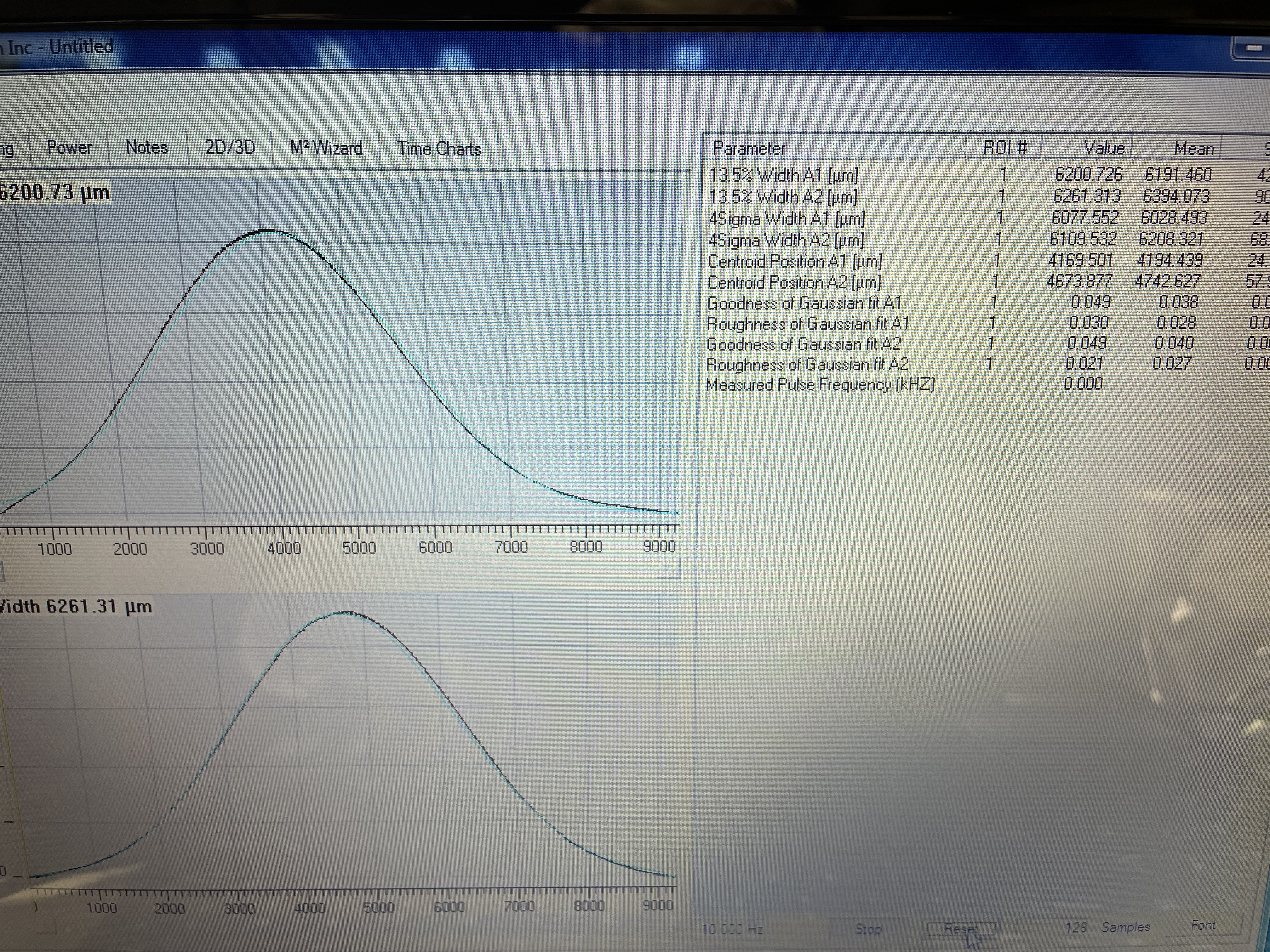
| 1 | 52 mm from dichroic M10 | 6243 | 64040 | here and here | 9022 | 9023 |
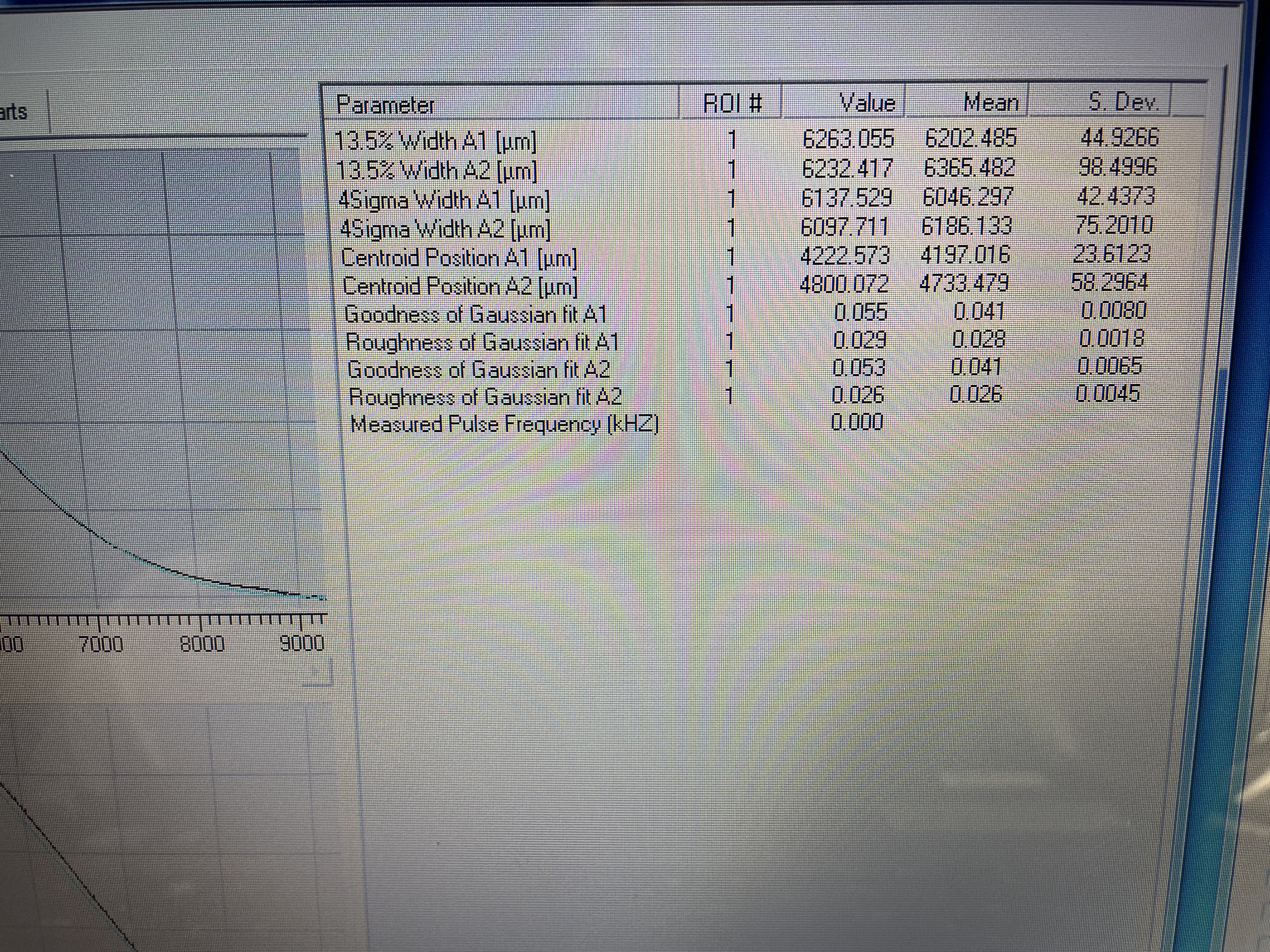
| 2 | 147 mm from dichroic M10 | 6202 | 6365 | 9028 | 9026 | 9027 |
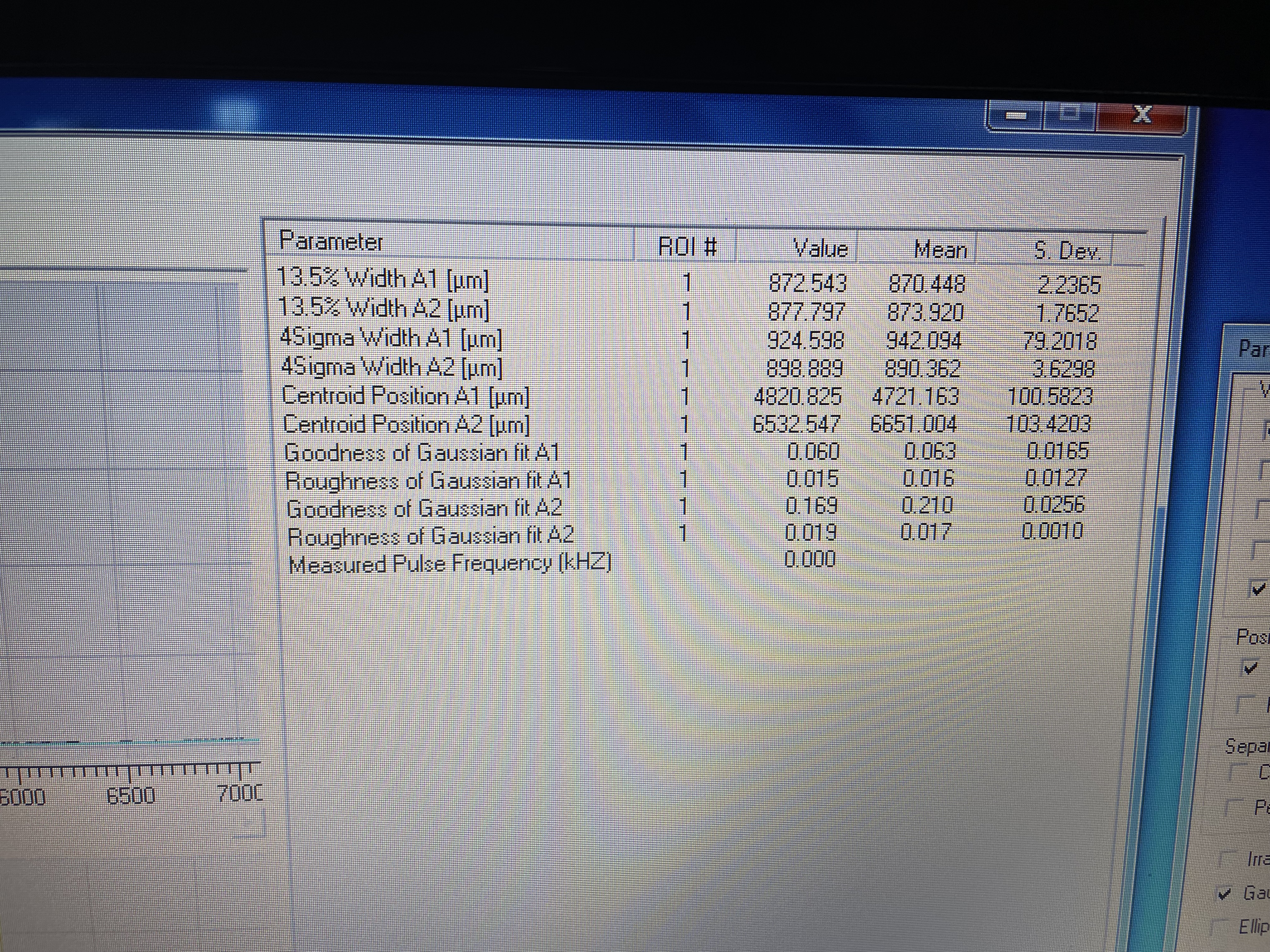
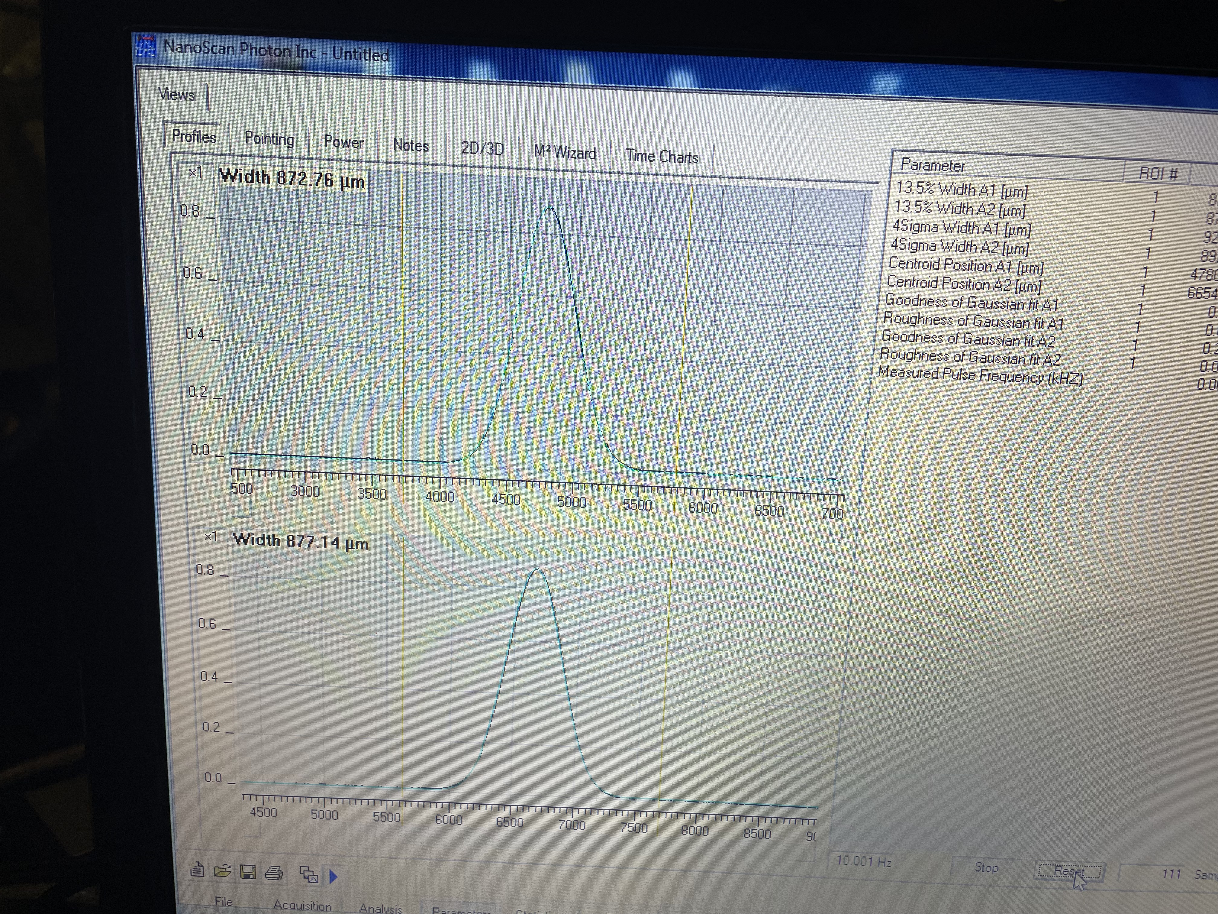
| 3 | 119 mm from HR of 50/50 BS M15, also 295mm from center of lens L2 | 870 | 874 | 9031 | 9030 | 9029 |
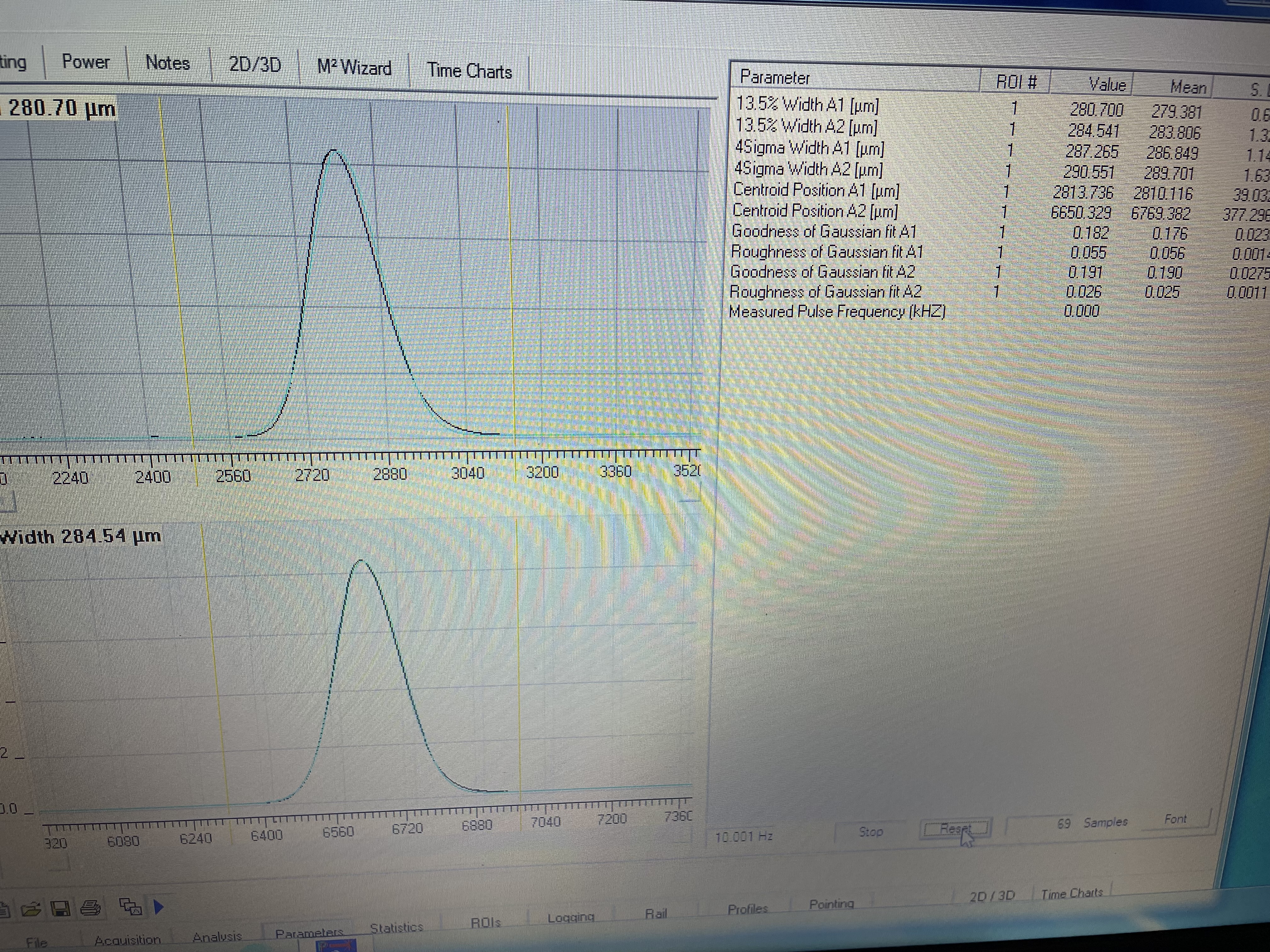
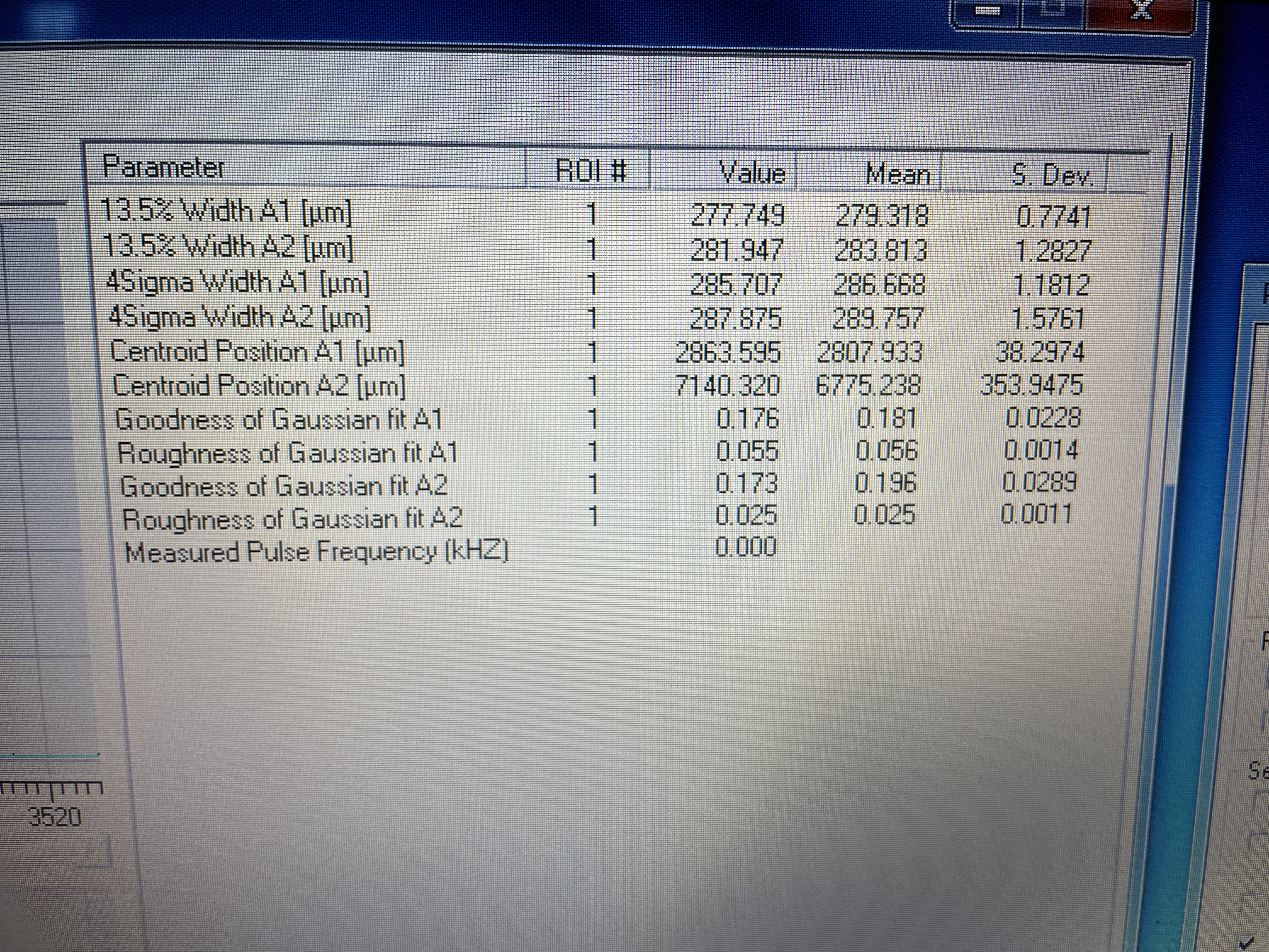
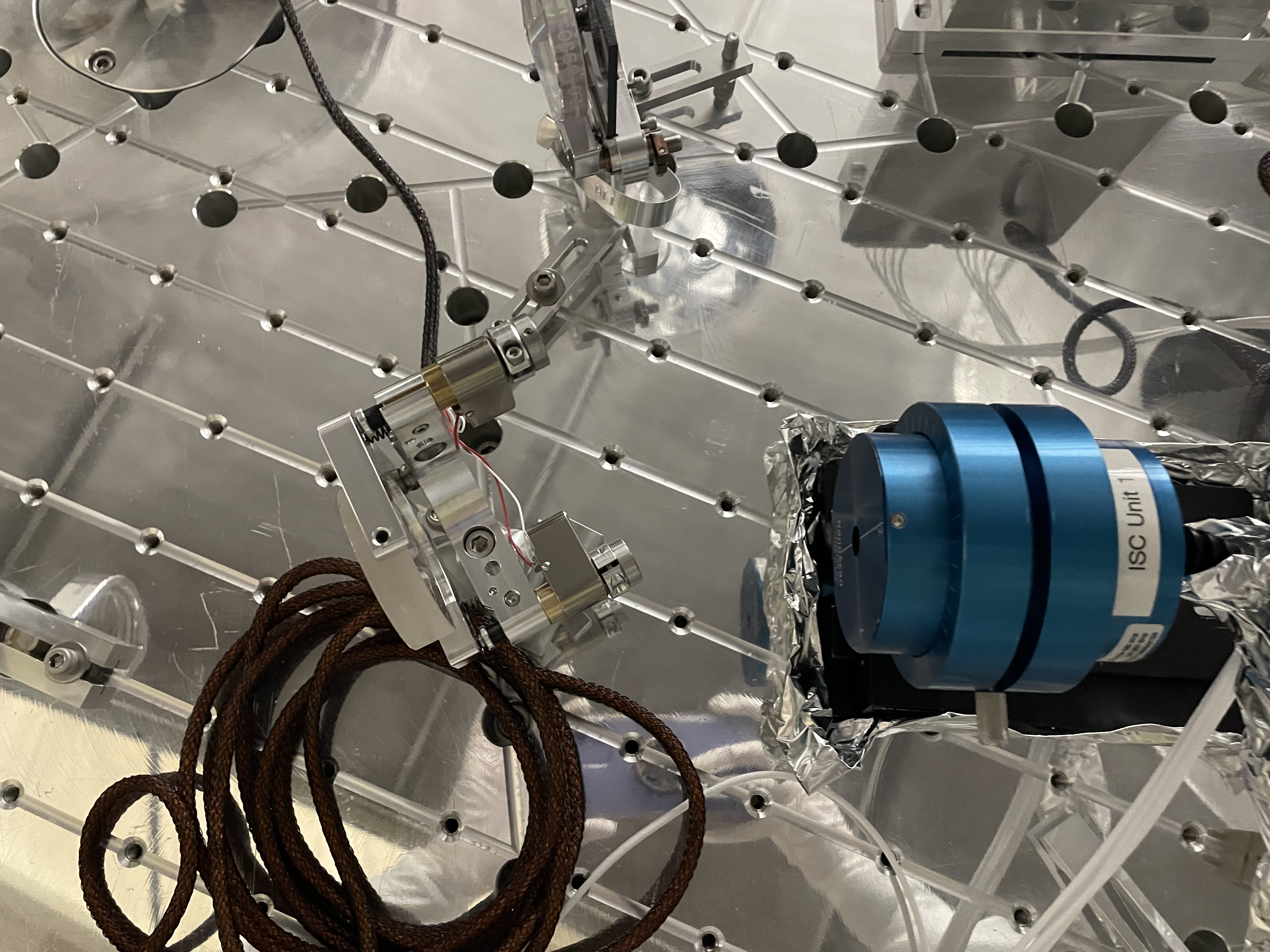
| 4 | 153 mm from HR of 50/50 BS, approximate location of LSC diode | 279 | 284 | 9035 | 9032 | 9033 |
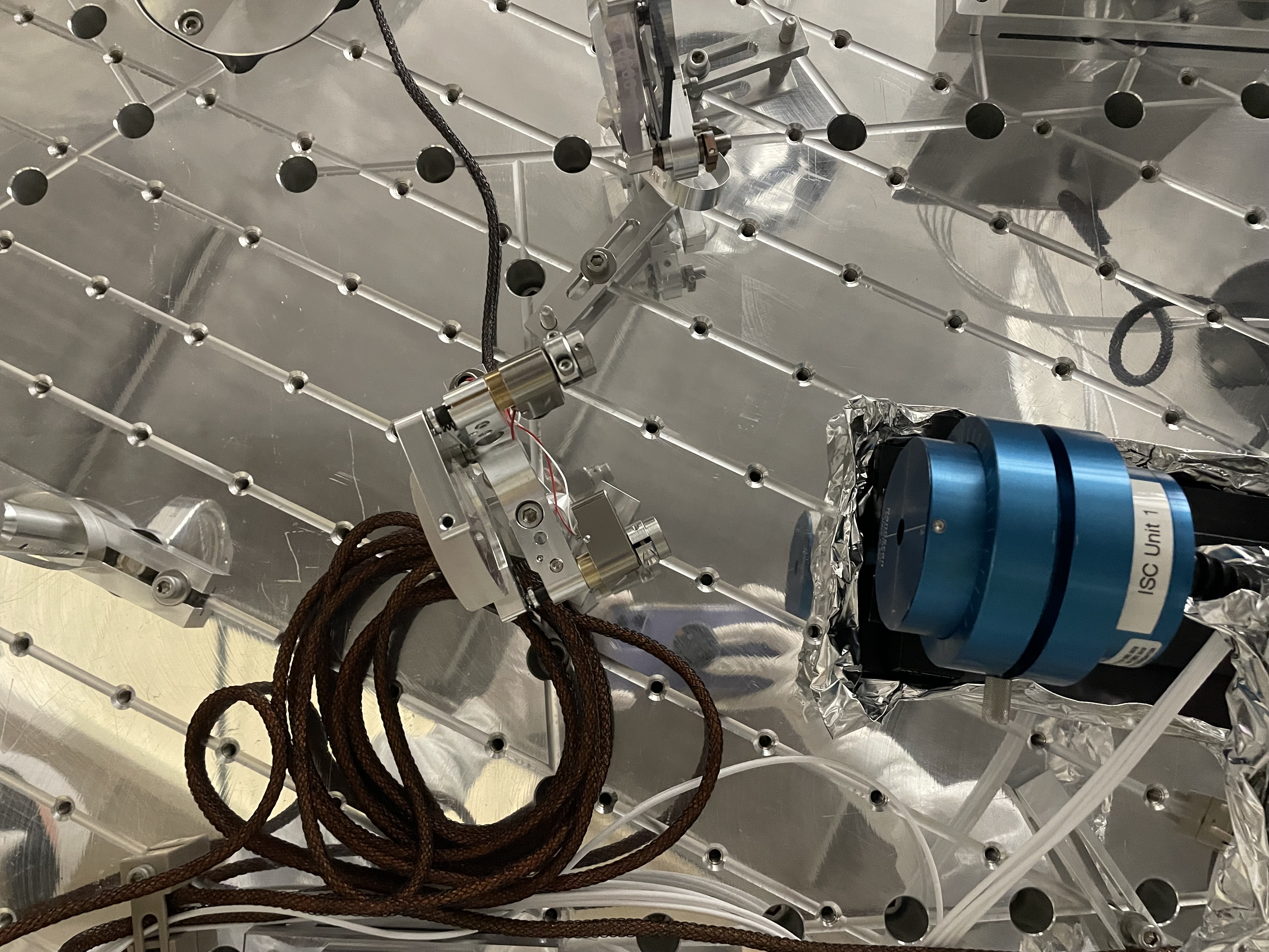
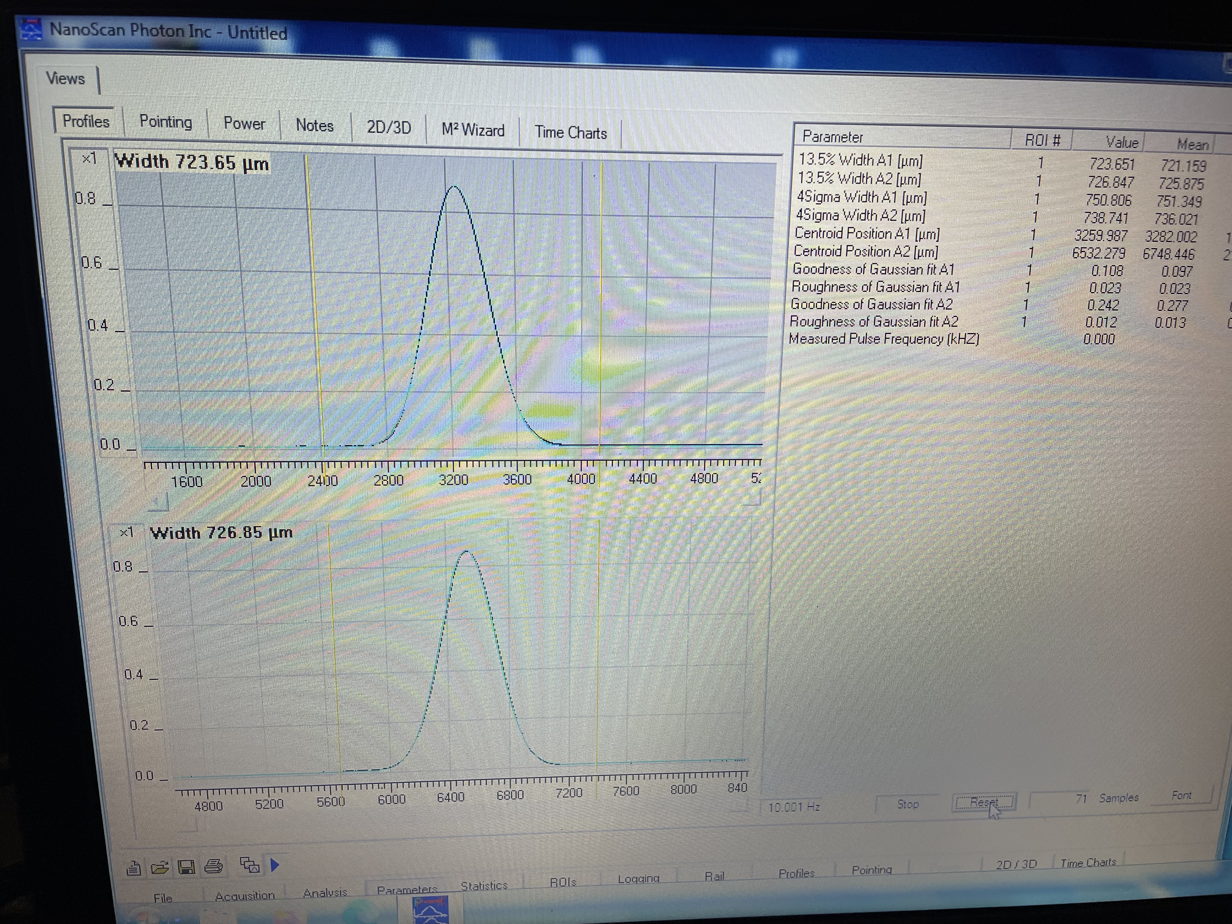
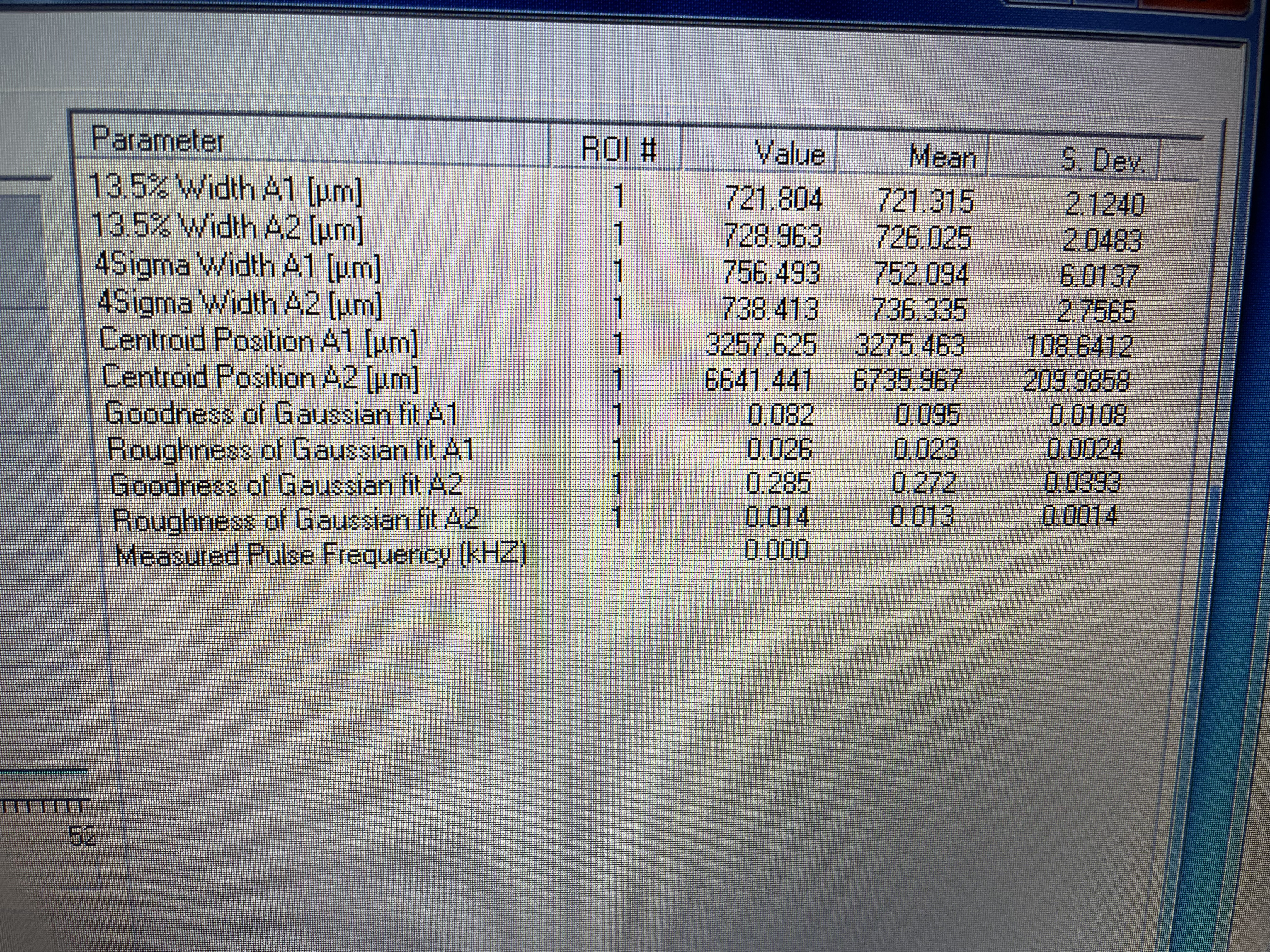
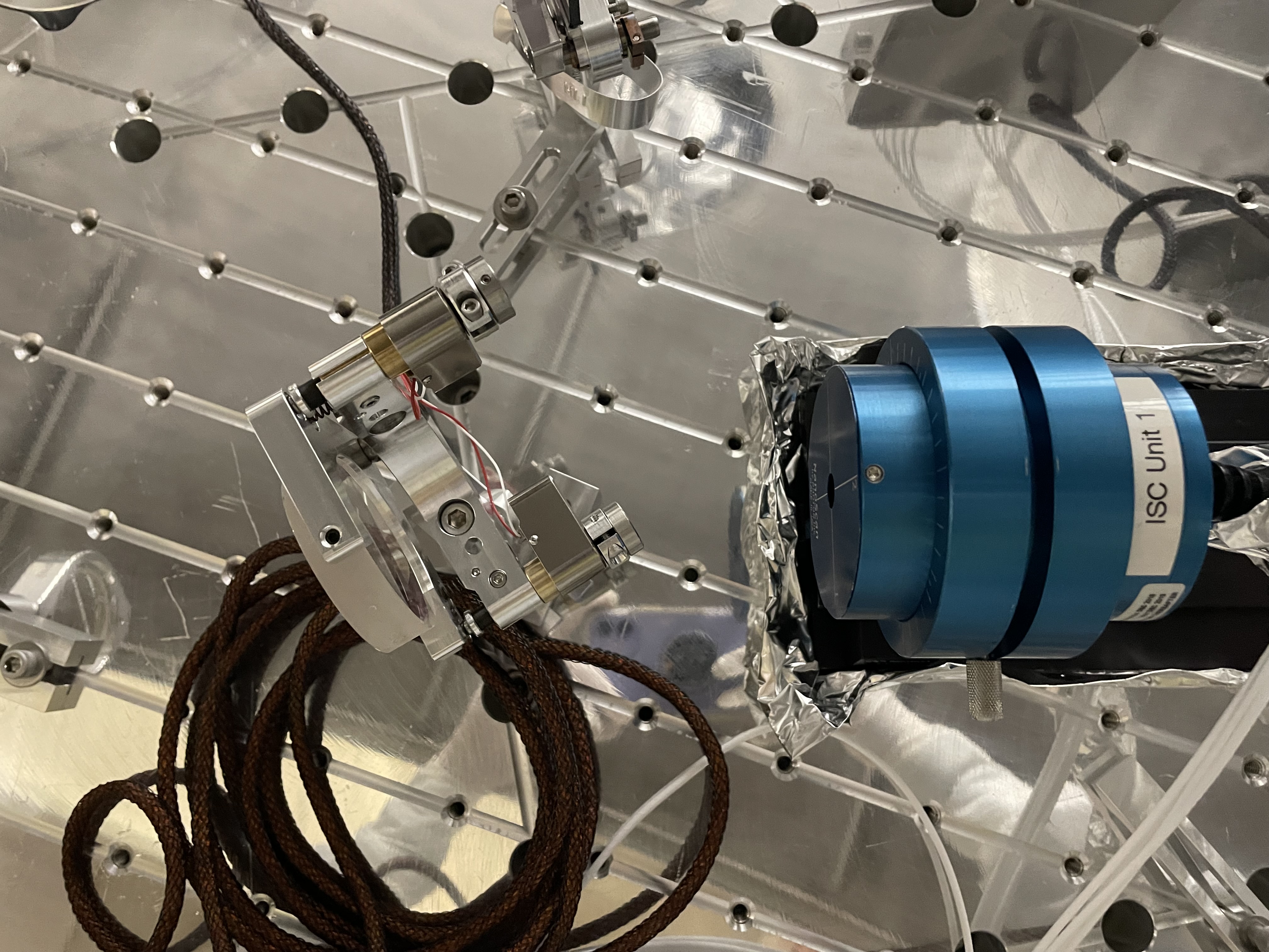
| 5 | 128 mm from HR of 50/50 BS | 721 | 726 | 9036 | 9037 | 9038 |
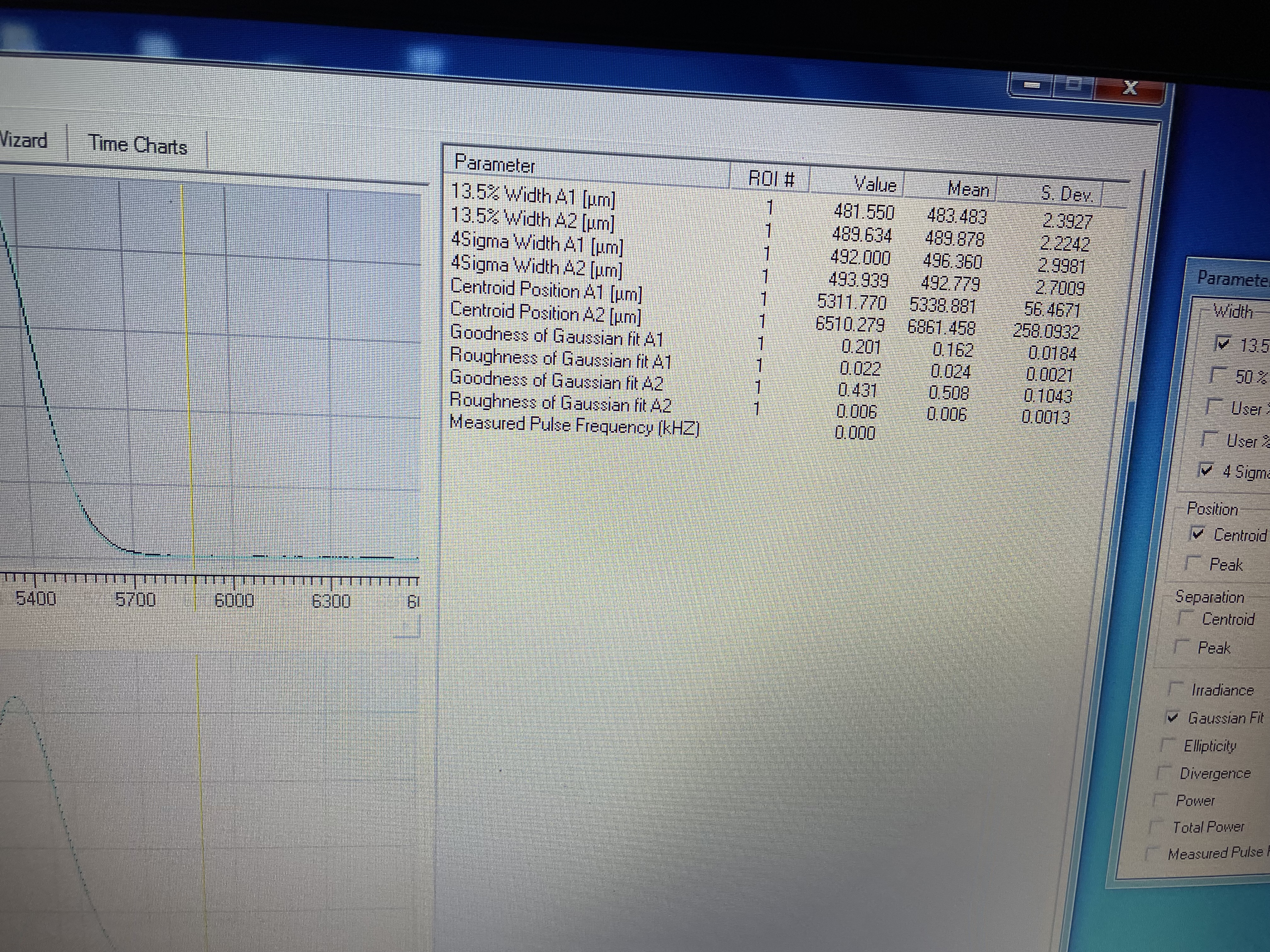
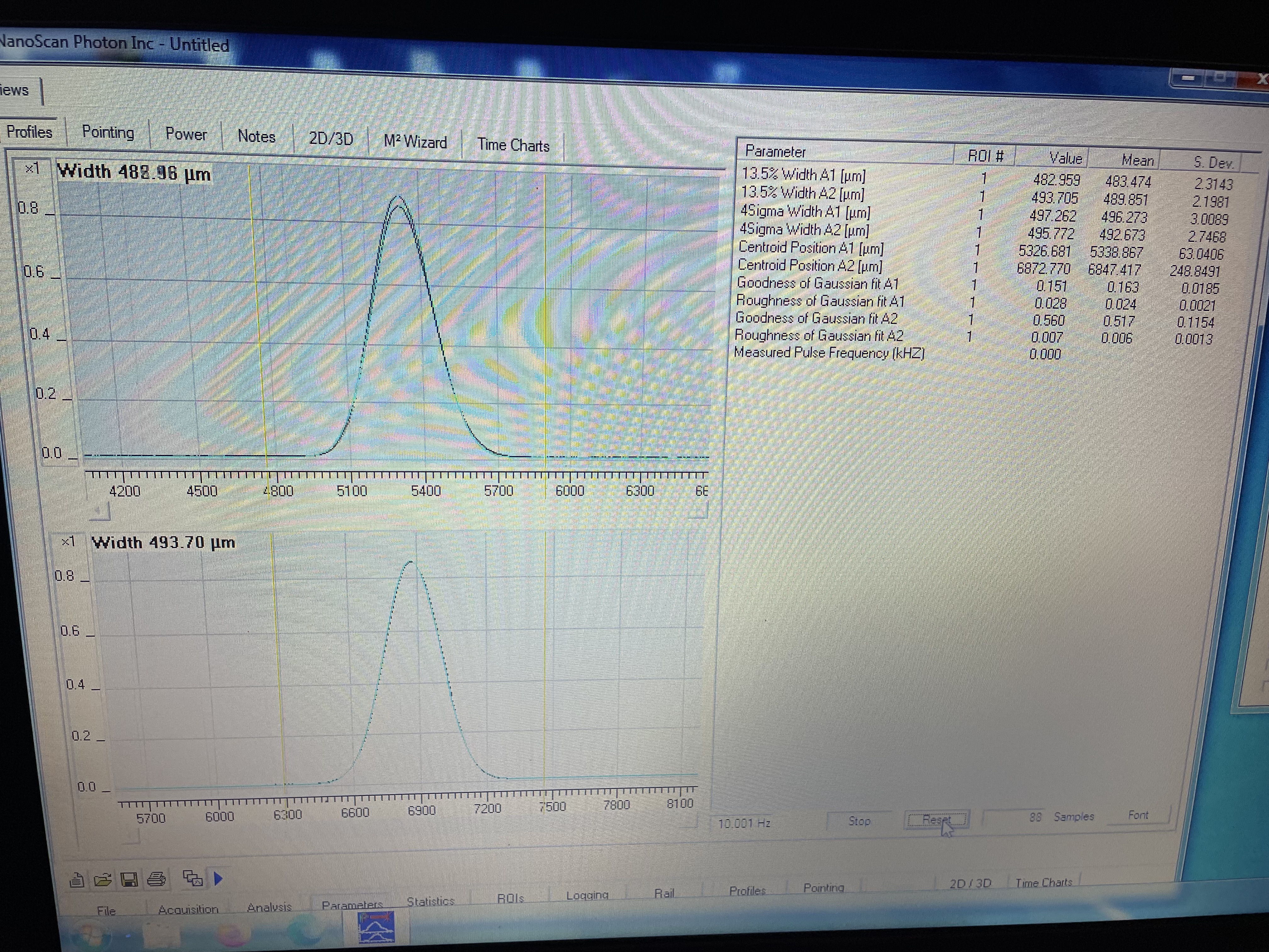
| 6 | 139 mm from HR of 50/50 | 483 | 490 | 9041 | 9040 | 9039 |
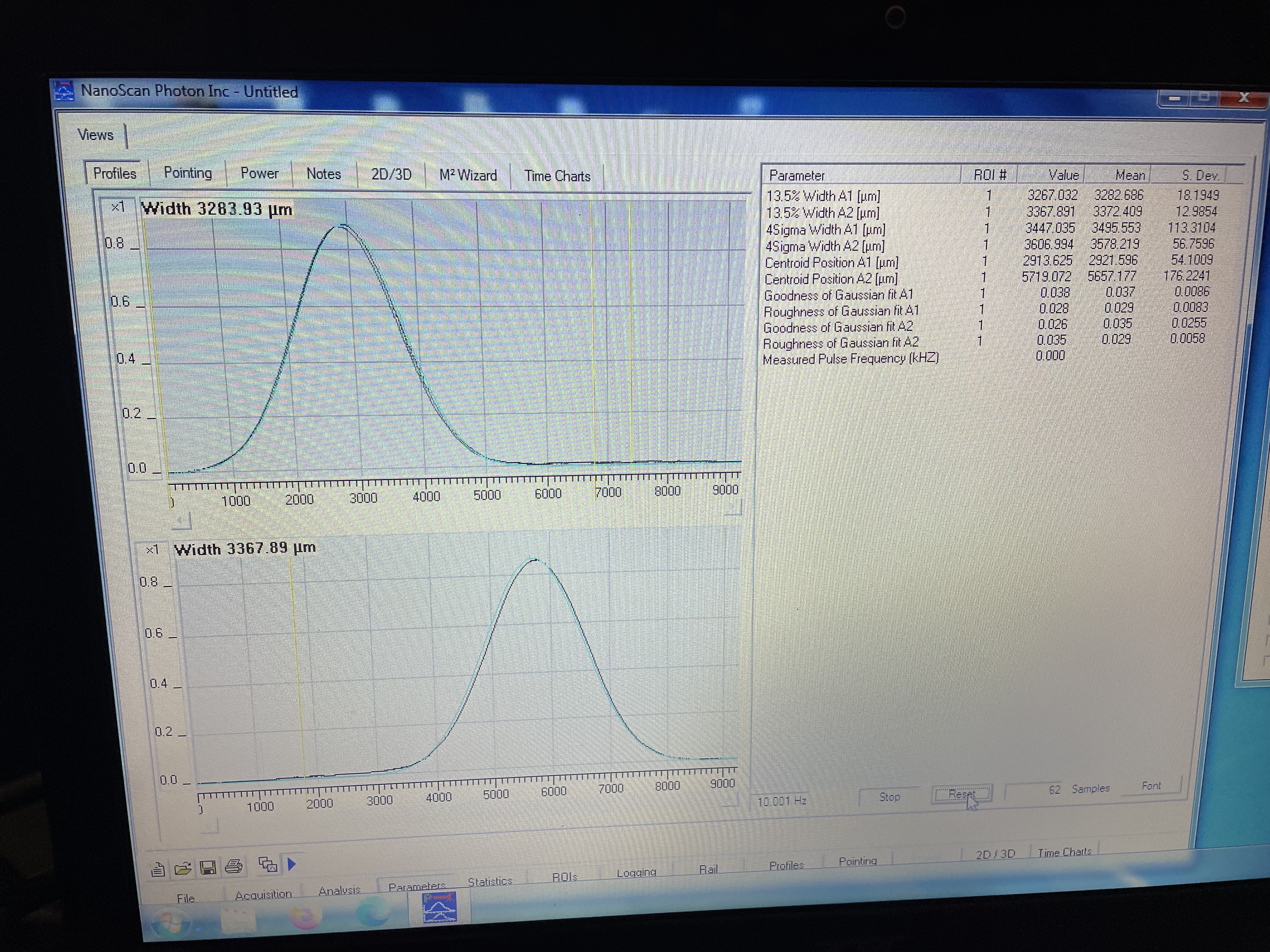
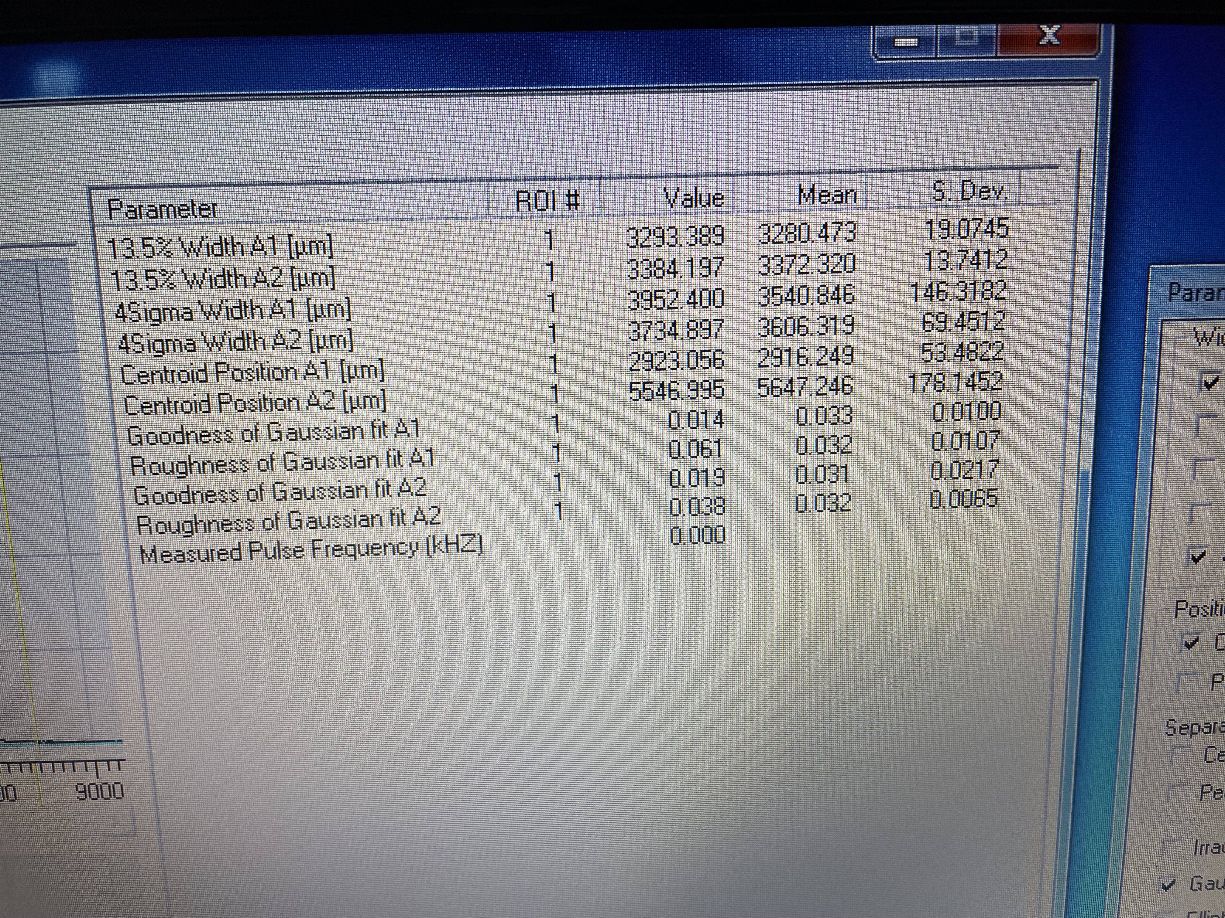
| 7 | 353 mm from HR of 50/50 BS | 3280 | 3372 | 9042 | 9043 | 9044 |
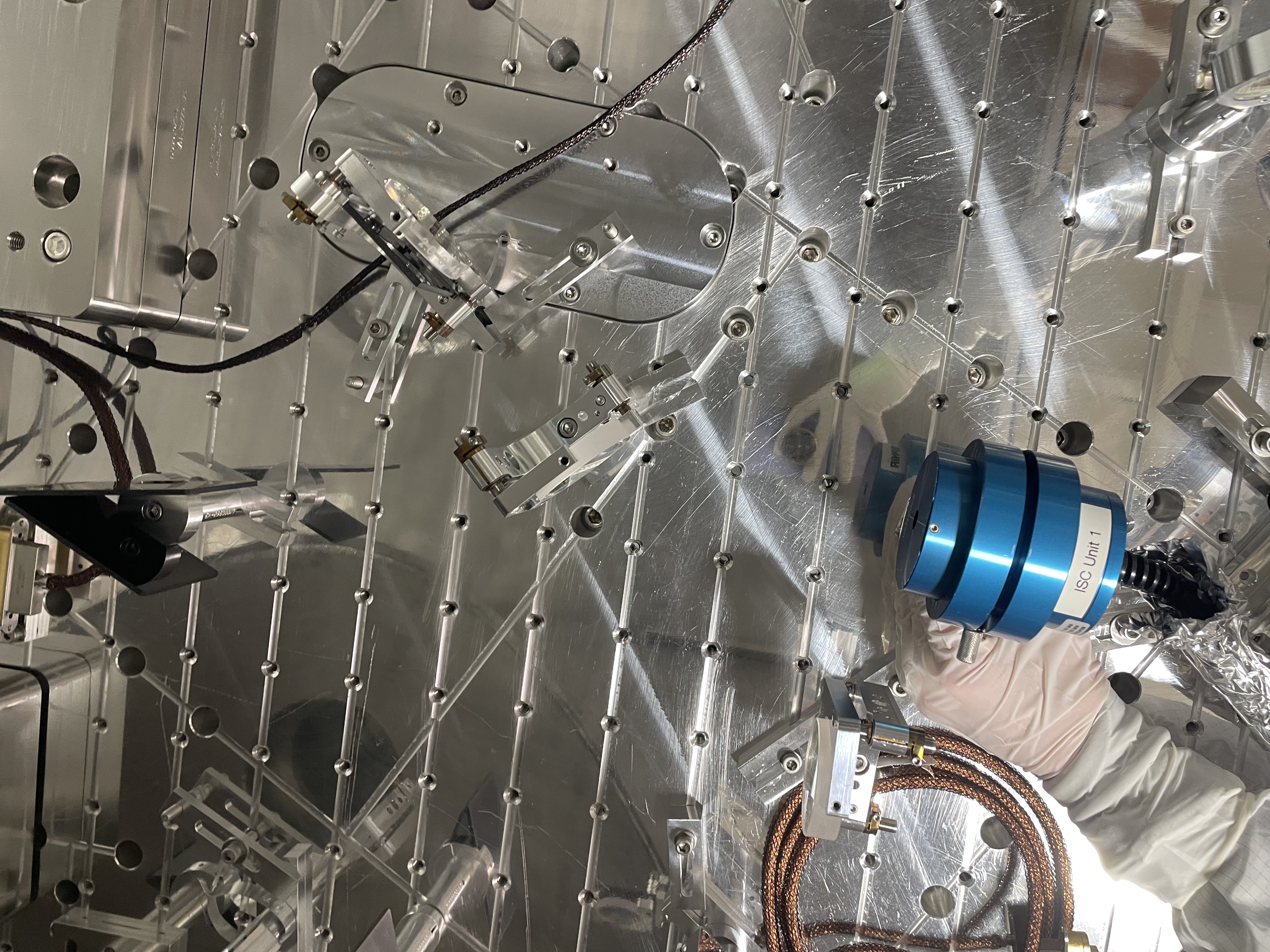
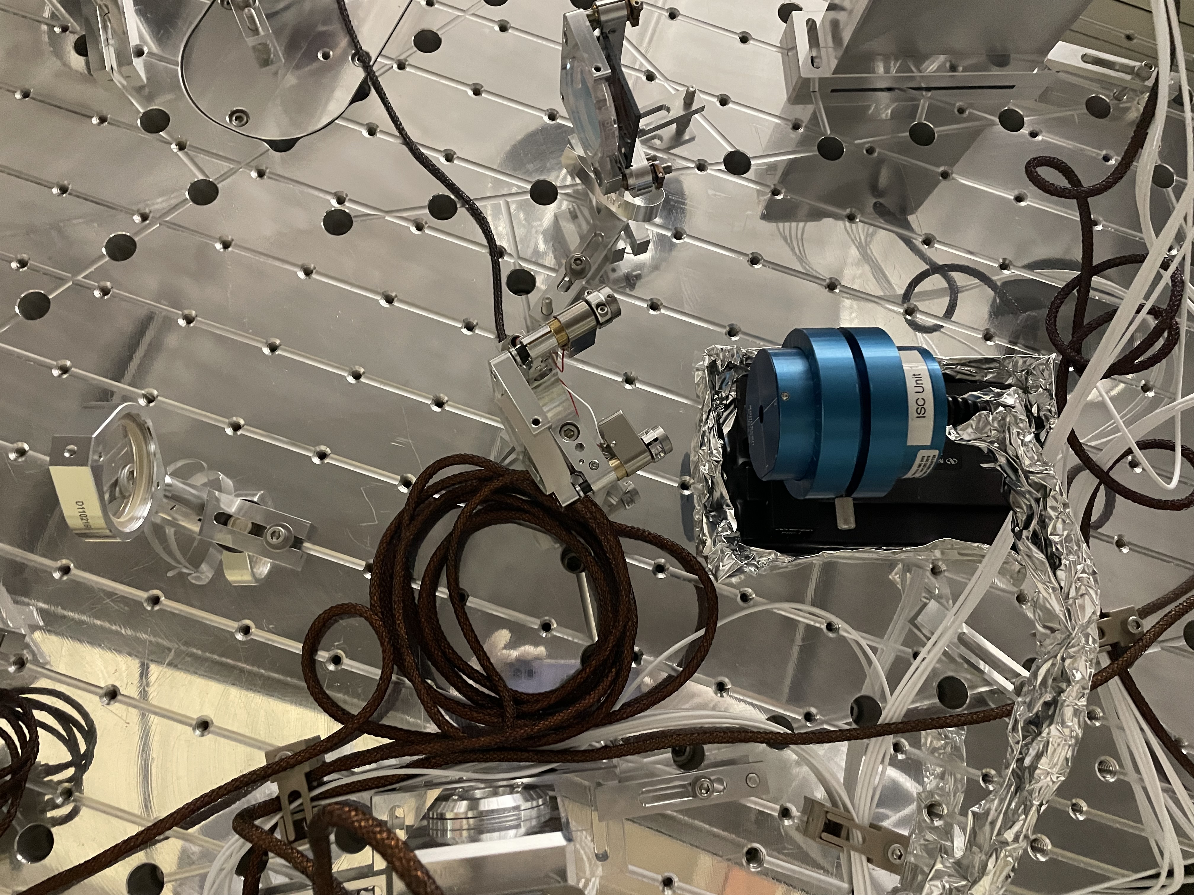
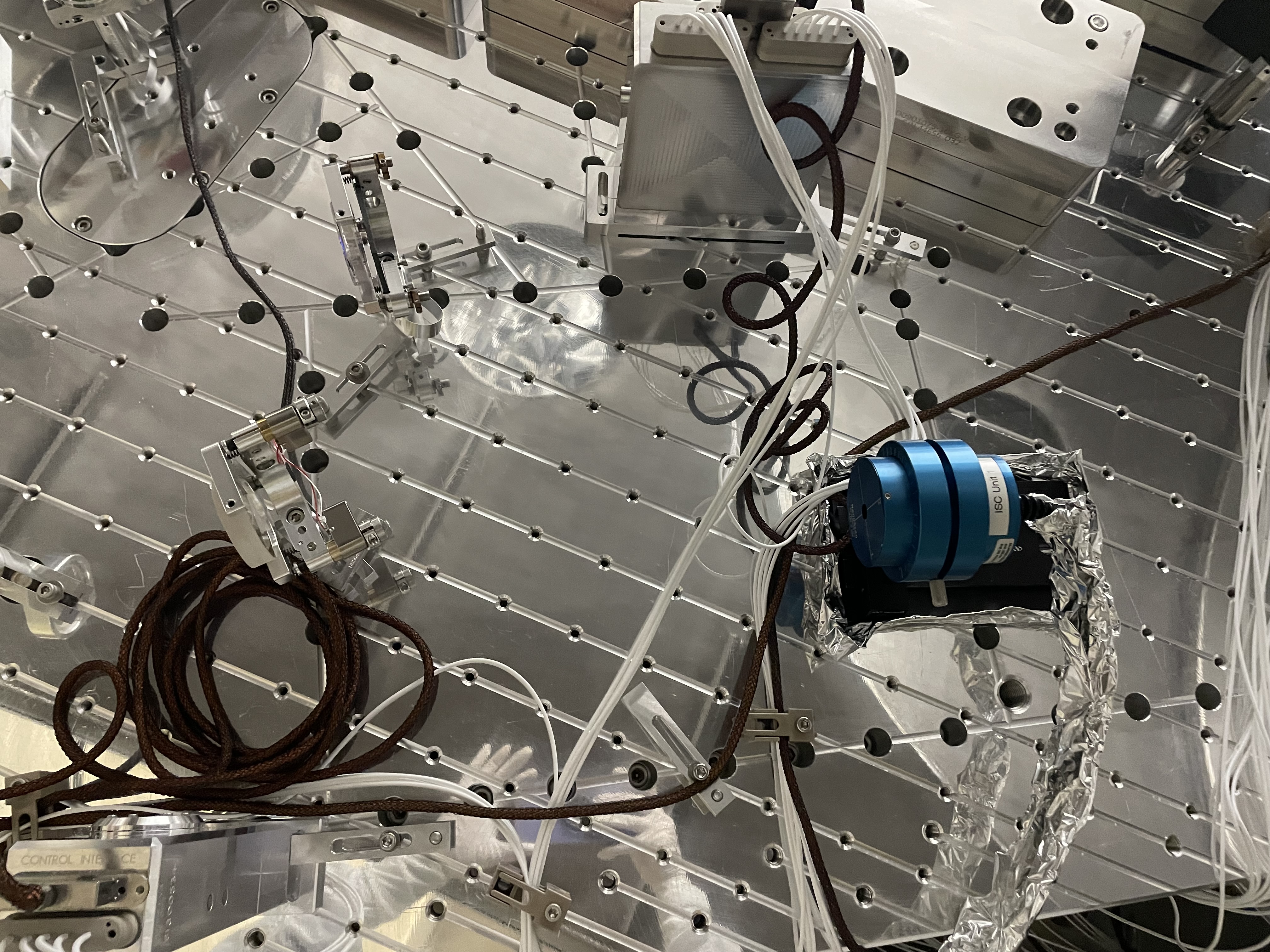
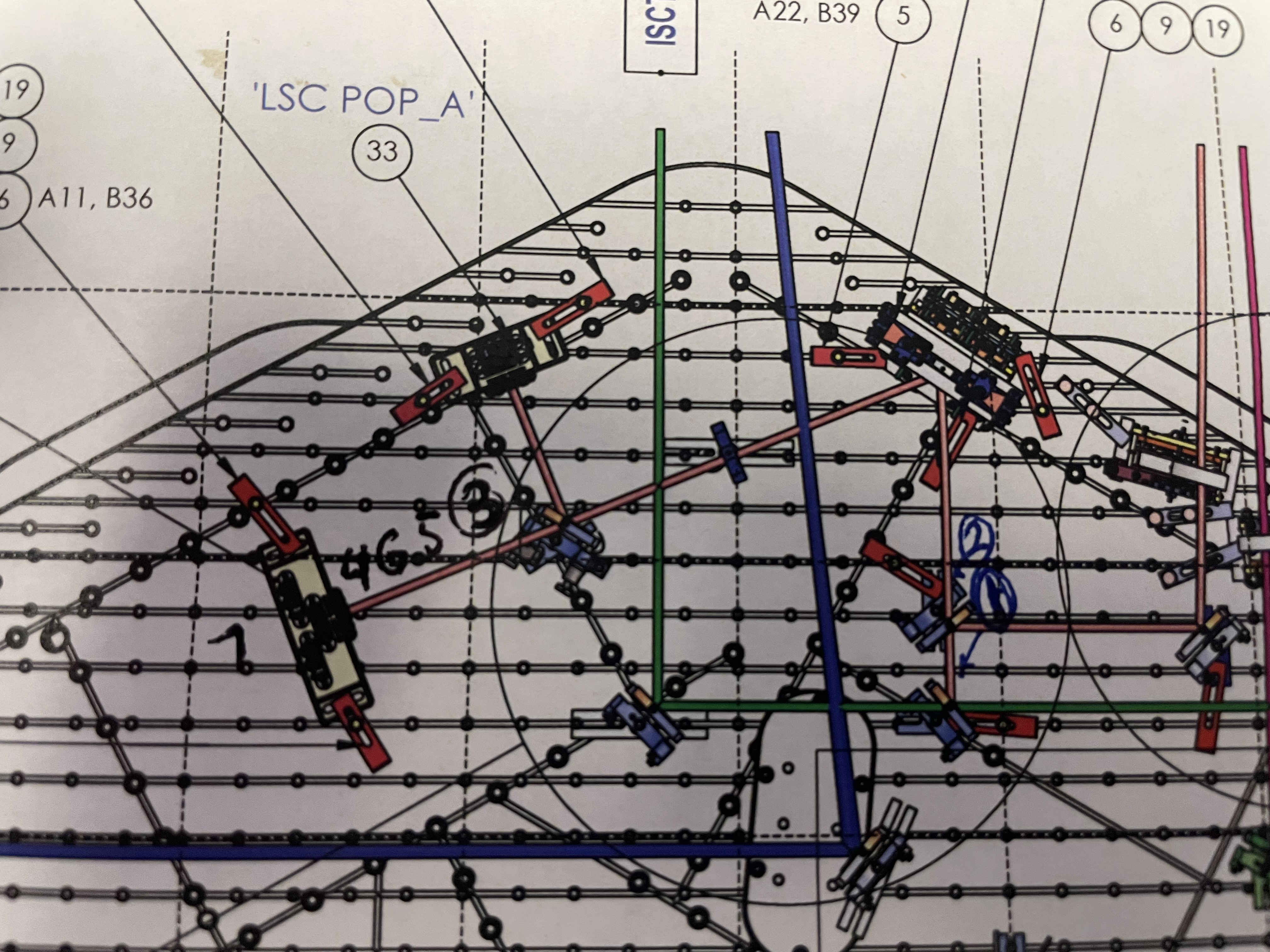
Camilla made these measurements with 20W input power into the IMC, PRM and ITMY misaligned single bounce beam. We didn't place the 90/10 BS M12 in the pop path yet so that we would have about 35uW to measure beam profiles. There's a rough pen sketch of where these locations are in this photo.
Camilla also made ruler measurements of some distances:
- PM1 to 50/50 BS M15 is 405mm
- PM1 to center of L2 is 229 mm
- center of L2 to M15 is 178 mm
- dichroic M10 to PM1 is 360 mm
- bottom of periscope (M8 or M9) to dichroic M10 482mm
- HR side of M15 (50/50 BS) to front of LSC diode box is 158 mm, diode itself is 3 mm proud of diode box.
I think these measurements look pretty good, and the result is not that much different than the model (at least in terms of where to put the diodes). The biggest surprise is that Keita and I were pretty sure the beam coming into HAM1 is just over 2 mm in radius, when in reality it is more like 3 mm in radius.
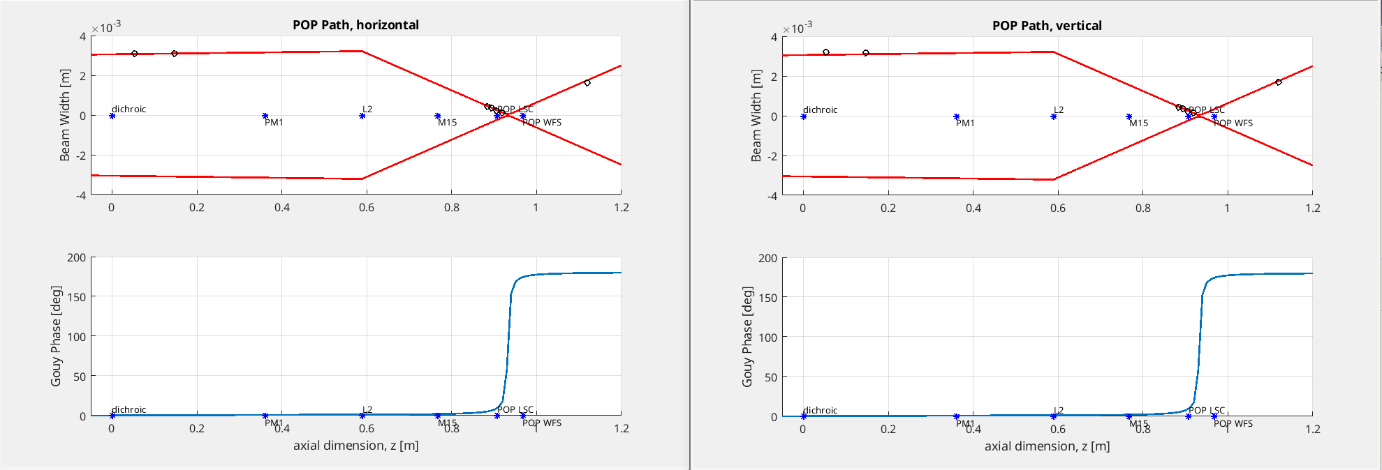
I have attached plots of both the horizontal and vertical propagations, but you can see that the results for each direction are very similar. The black points are the measurements Sheila and Camilla took today, and I fit them with a la mode and the 2 inch POP lens (f = 334 mm), using the distances from the dichroic mirror that Sheila and Camilla measured.
If we place the POP LSC diode about 140 mm from M15 and the POP WFS about 200 mm from M15, we should get the beam sizes we want on each. I think these positions are a little closer to M15 than they are in the drawing, but I don't think that's a problem.
I also attached my a la mode script.

Linking here that Keita added distances to the refl air and popair periscopes here: https://alog.ligo-wa.caltech.edu/aLOG/index.php?callRep=84345
Here is the layout to reference optic numbers listed above: D1000313-v20
And here are Corey's chamber close out photos: 84561