Morning (JennieW, Rahul, Keita)
We used the PRX flashes to align the POP path.
POP periscope location is good but the drawing is not.
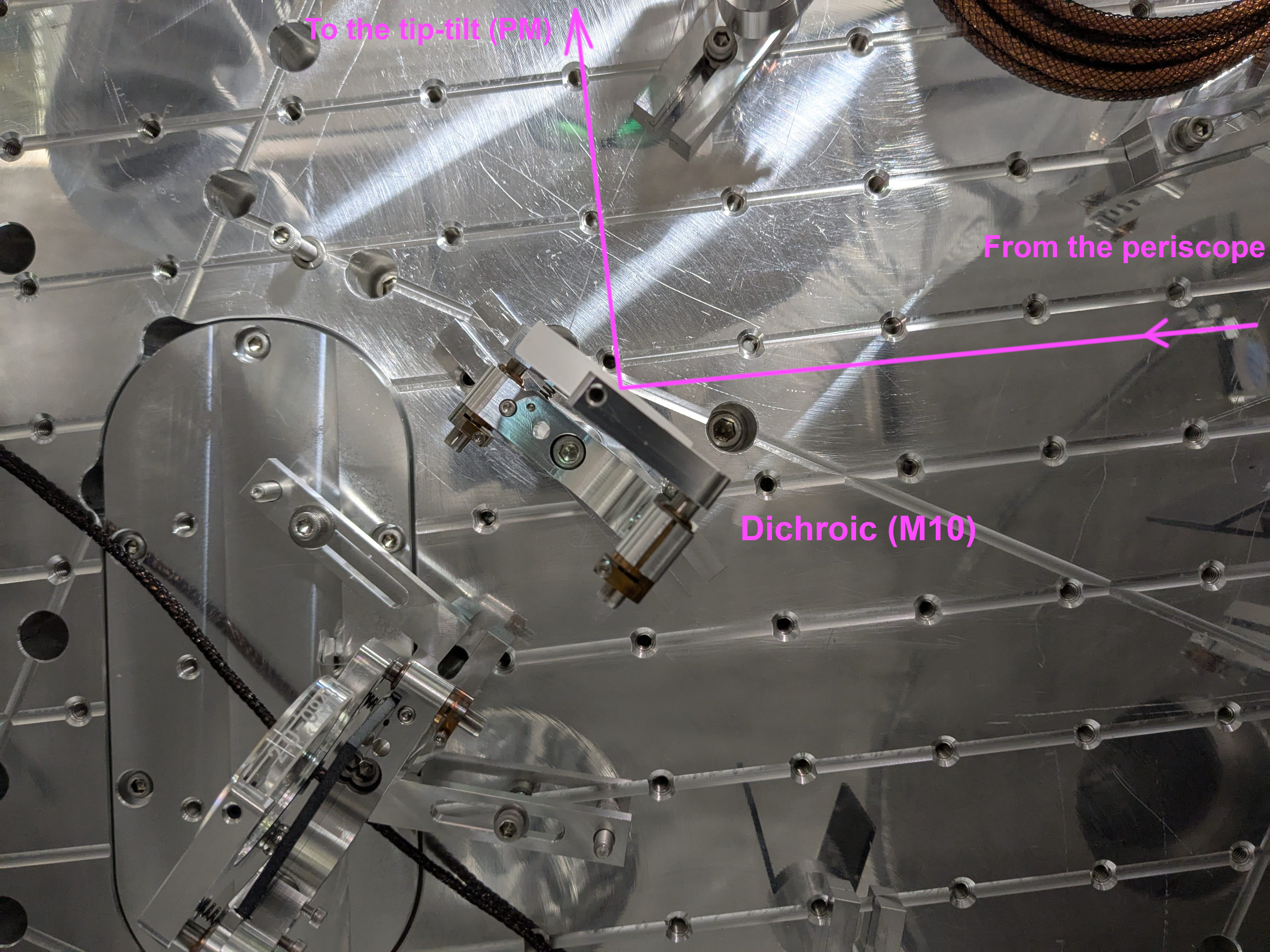
The POP periscope position, which was set yesterday by Camilla and others, was right. That means that the drawing on D1000313-v19 is wrong. The periscope in reality is about an inch toward -Y direction relative to D1000313-v19. See the first picture, which was shot with a cellphone inserted under the top periscope mirror and looking straight down the bottom mirror. This means that the dichroic (M12) needed to be shifted by the same amount too.
Since the distance betwen the IFO and the lens for POP WFS doesn't matter that much, everything downstream (i.e. 90:10, PM1 tip-tilt, a lens, 50:50 and POP LSC as well as POP WFS) will be installed using the drawing.
We mainly rotated the periscope mirror clamps around the post for rough alignment, but we might have changed the mirror height by a millimeter or two in the process.
PM1, which is calld that because it's the 1st (and the last) suspended Mirror for POP, is somehow called RM3 in D1000313. Systems please fix it.
Set the IR beam spot height/position on the periscope as well as the dichroic
The IR beam is supposed to be about 6mm or 1/4" lower than the center line of both of the periscope mirrors as well as the dichroic. This is because the green ALS beams are supposed to be ~13mm higher than IR. See L1200282 “CPy-X, CPx-Y” case on Table 1.
Top Periscope Mirror
It was almost impossible to see how much the beam is lower than the center of the top and bottom periscope mirror. Using the IR viewer card, I and Jennie agreed that the beam is lower than the center, but we could not quantitatively say how much especially on the top. We'll leave it as is, and if the green beam from the end station is too high we will have to use pico because we periscope is already as high as possible.
Bottom peri mirror
If everything is as intended, the bottom periscope mirror is 4" high from the ISI surface and the POP beam is 1/4" lower than that, therefore the POP beam is (1-0.25*sqrt(2)) = 0.646" = 16.4mm away from the bottom edge of the mirror.
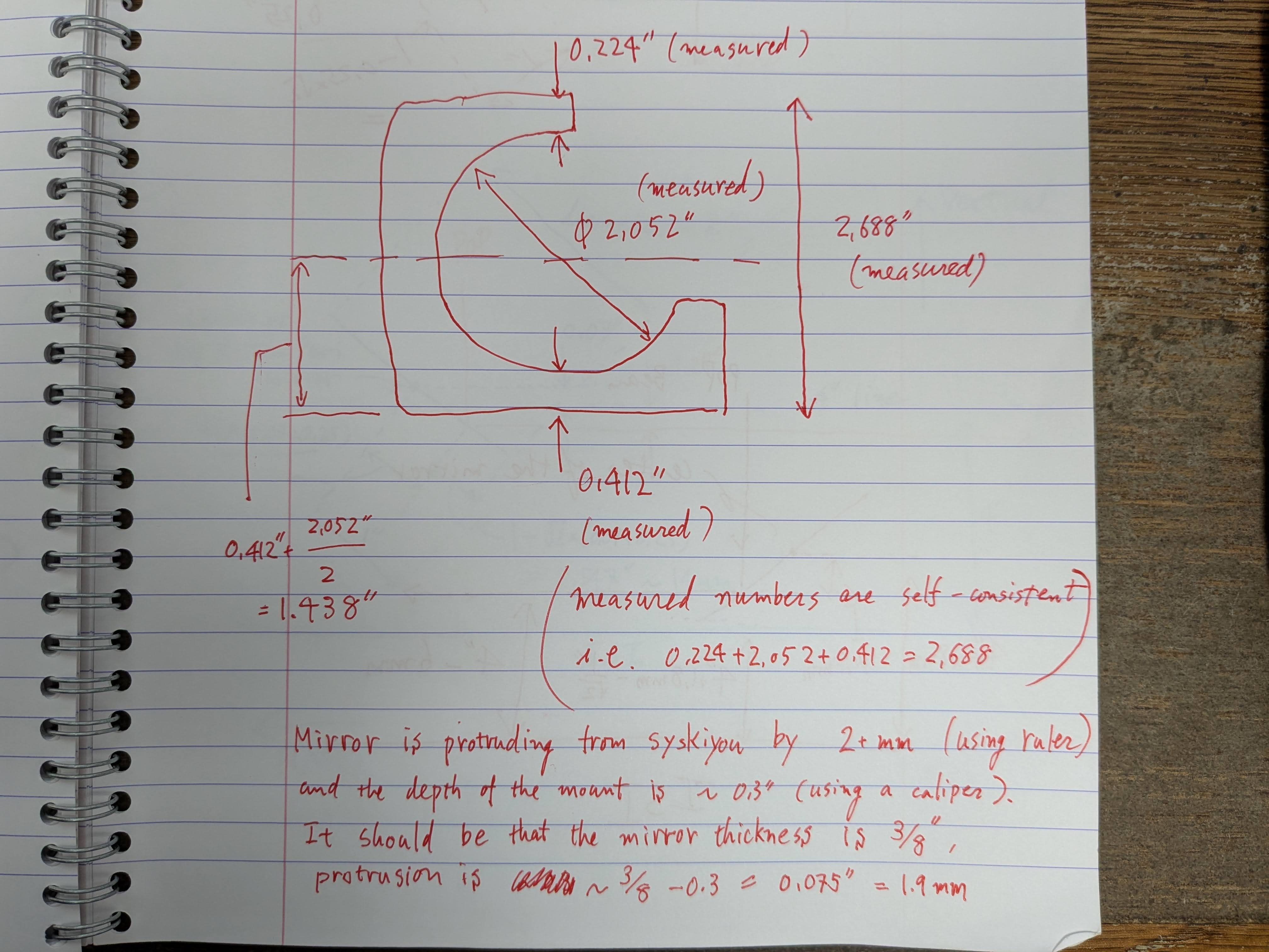
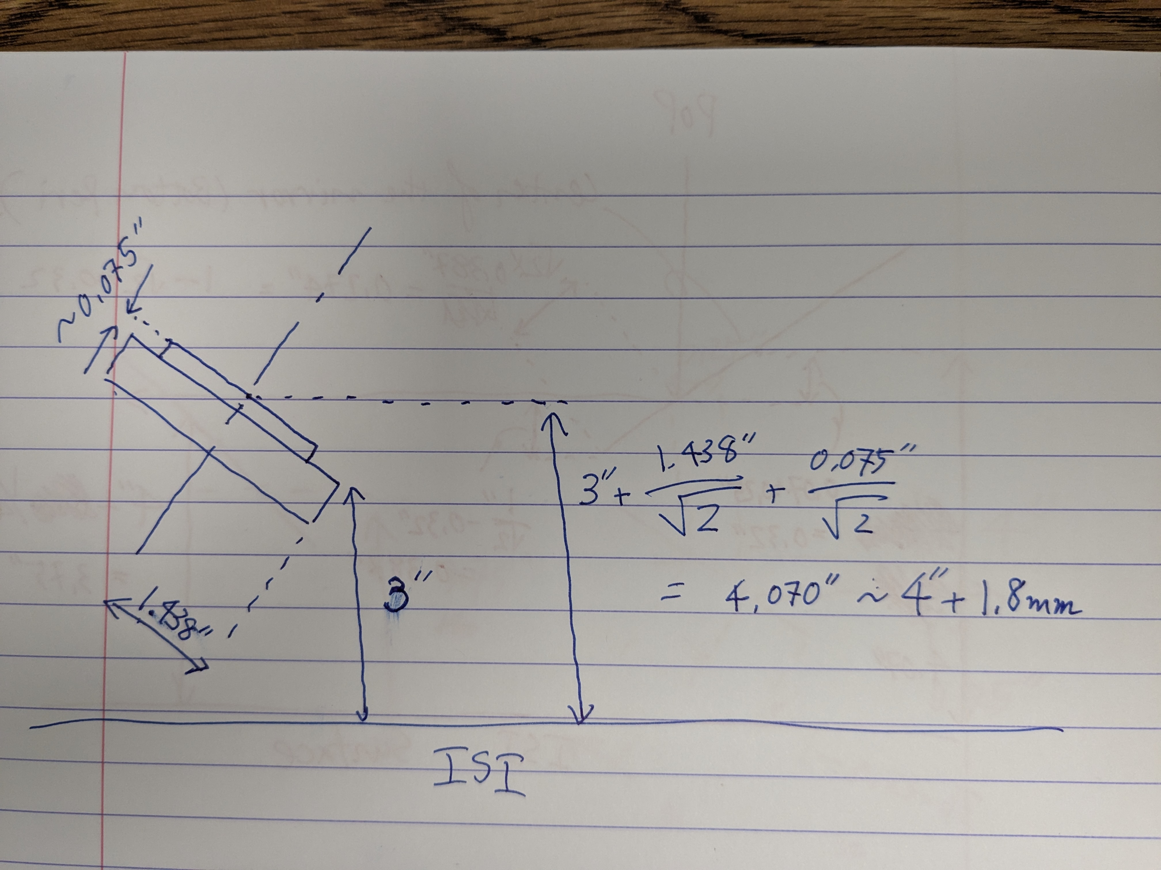
Using a ruler in chamber (and measuring the dimensions of a spare Siskiyou mount using caliper), the height of the bottom periscope mirror center was calculated to be ~4.07" from the ISI surface, i.e. 0.7" too high. This means that, when the beam height measured from the ISI is as designed (i.e. 4"-1/4"), the POP beam is (1-(0.25+0.07)*sqrt(2))=0.547"=13.9mm away from the bottom edge of the mirror.
If you have difficulty understanding this, see the cartoon.
POP beam radius is ~2mm, so 13.9mm (or even 13mm for that matter) looks like a safe distance to me. I don't see the need to readjust the height of the bottom periscope mirror.
I adjusted the top periscope mirror to set the beam height right after the bottom peri mirror to be ~3.75" using the IR viewer card and a ruler.
Dichroic
I placed the dichroic about 1" into -Y direction relative to the drawing (because I had to), and used the bottom periscope mirror to set the beam height close to the dichroic to be ~3.75".
Then I used the dichroic to steer the beam into the direction of the location for PM1 without placing 90:10.
For the beam profile measurement, the downstream alignment is done without 90:10. Later we will install 90:10 back in place and do the final alignment.
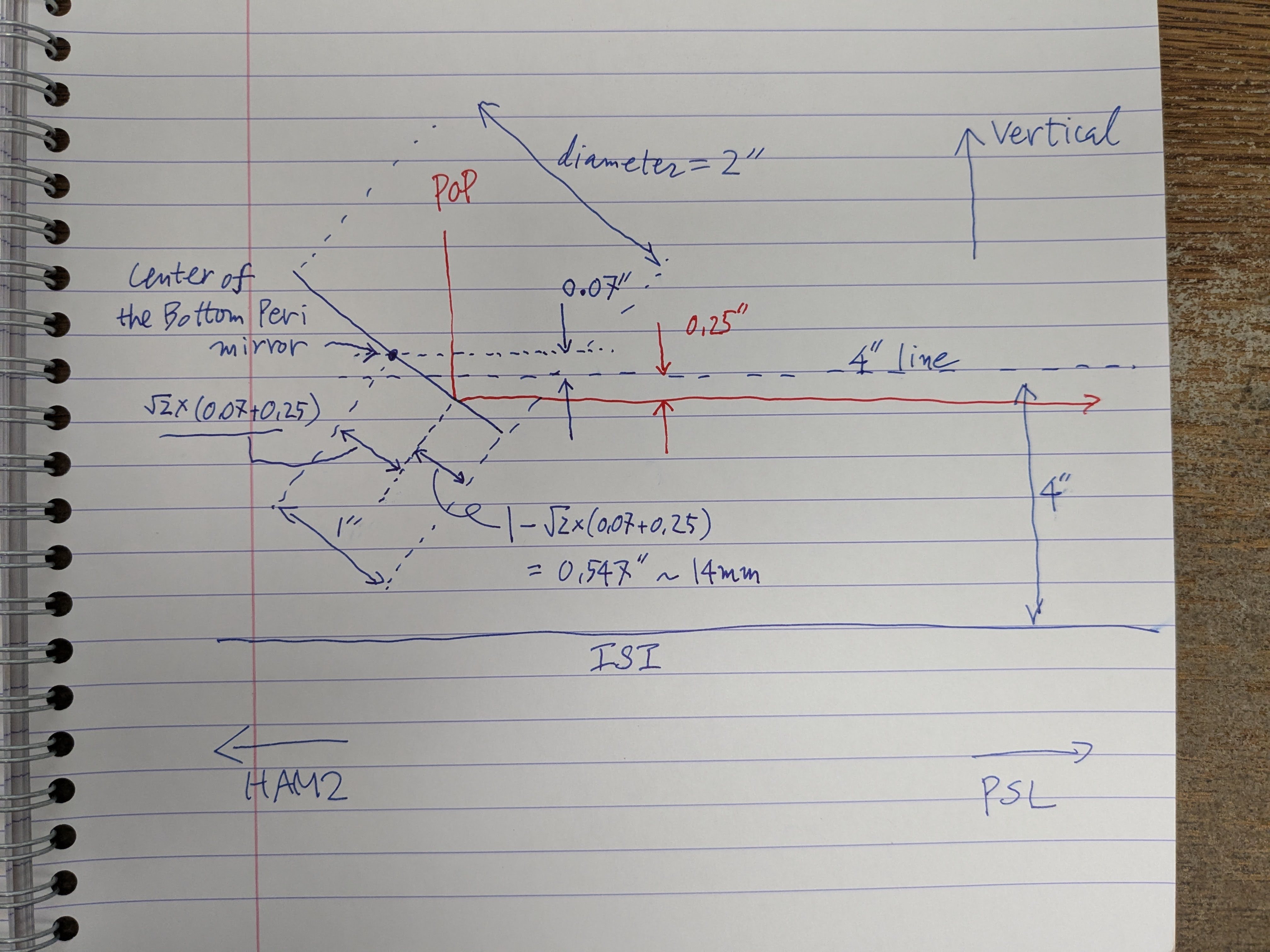
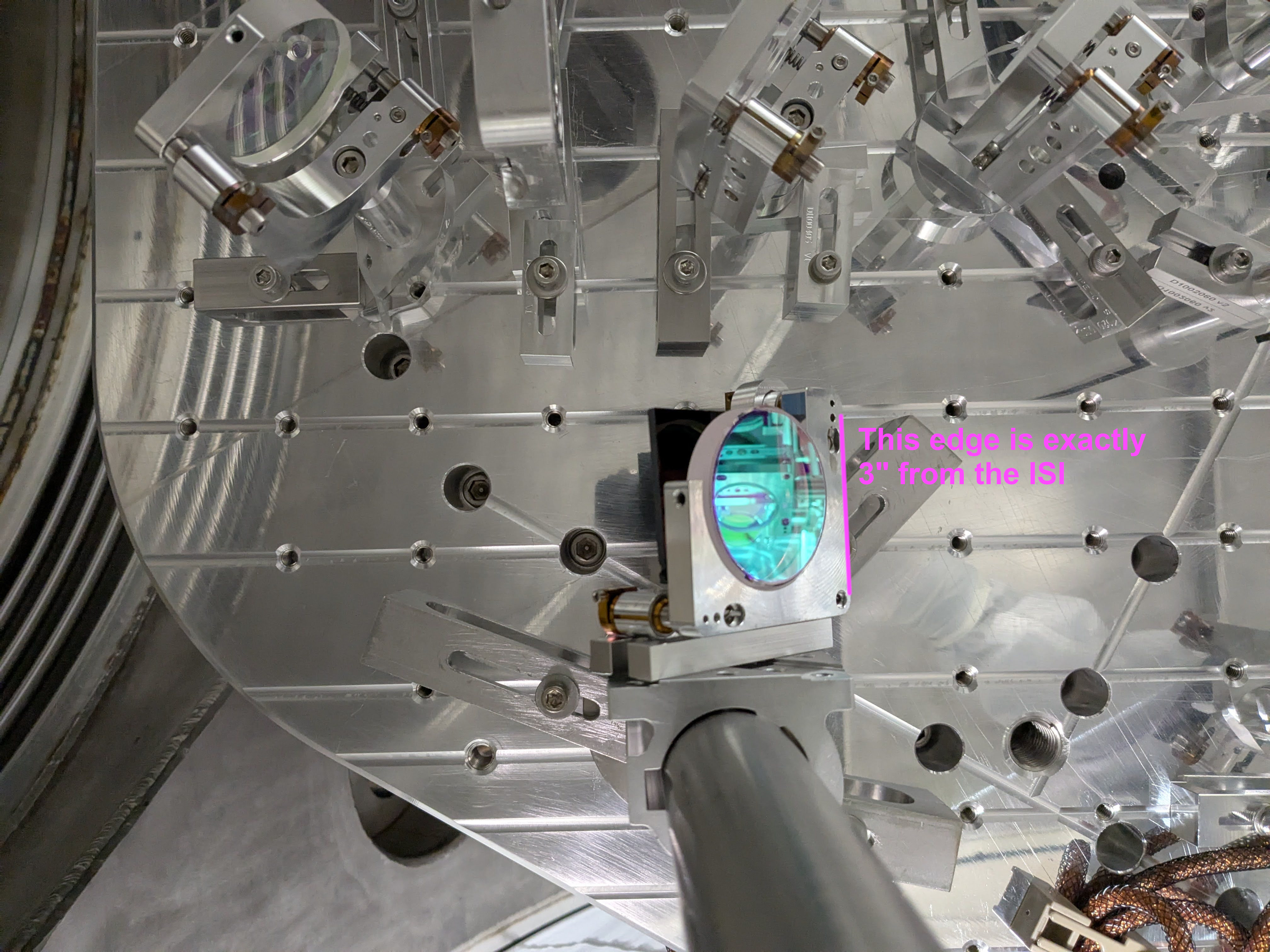
And here's a memo of how we "measured" the height of the center of the bottom periscope mirror.