[Sheila, Elenna]
Alog 84230 contains an extensive report of the beam profile measurements in HAM1 along the REFL path. Keita did a fit of the measurements along the WFS sled to determine that the gouy phase separation of the REFL WFS is good. I have now taken all the data, starting just before RM1 through the WFS sled measurements and run a fit.
Looking back at T1300960, which does a similar fit model from the measurements in the REFL path, there is some confusion about what the input q to HAM1 is, and this resulted in some doubt about the radius of curvature of both RM1 and M5, whose design specs are 1.7 m. That code uses RoCs that are 1.75 m for each mirror, which Sheila and I think is a bit far out of the range of the specification (see E1100056).
There is a total of 8 measurements, four taken around the WFS sled and four taken around the RM1-RM2-M5 area (a ninth measurement of the beam size at the LSC REFL diodes is not included). I added these measurements to the model, as well as RM1, RM2, M5, L101 and L102. I ran a fit based on these components and the beam profile measurements.
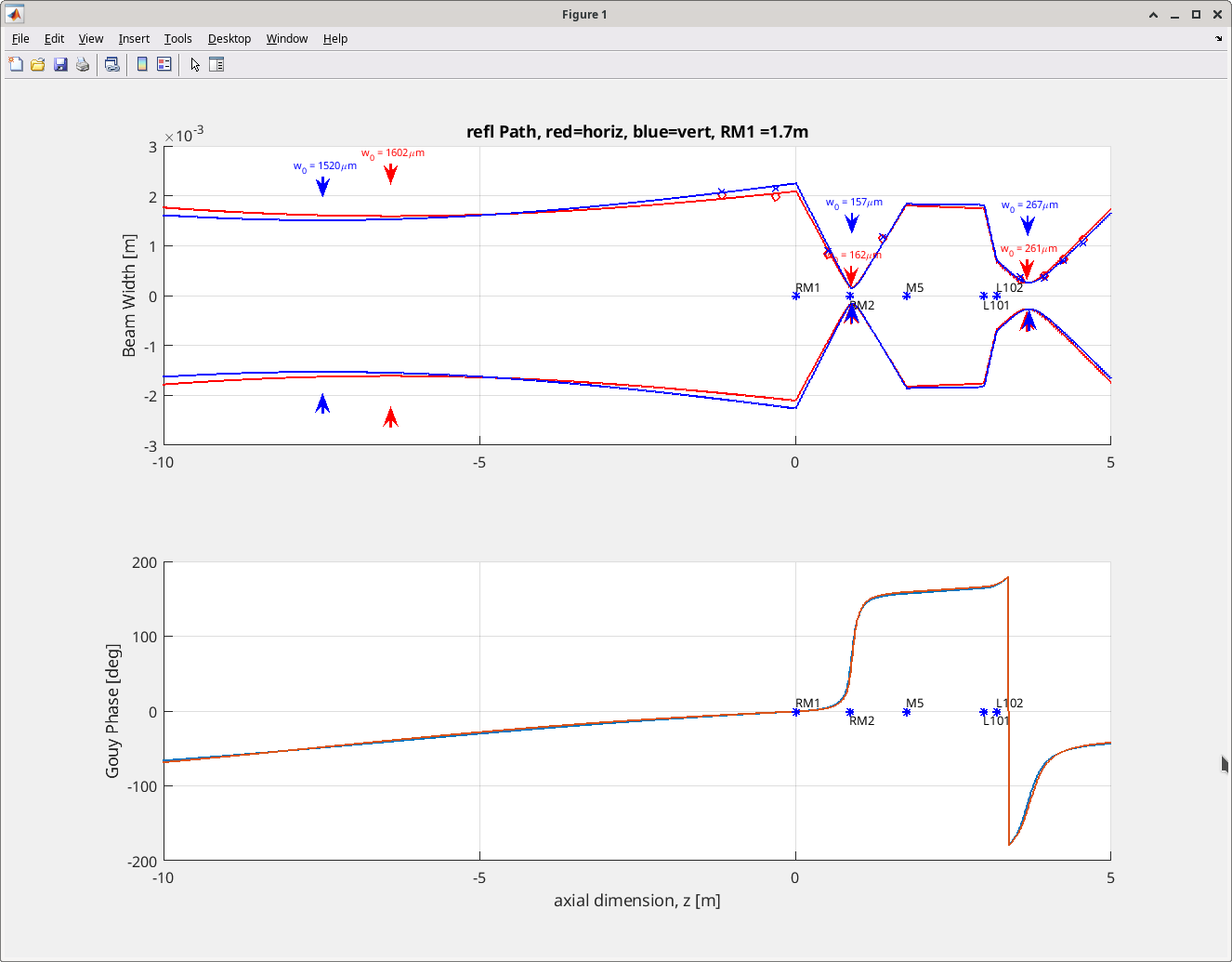
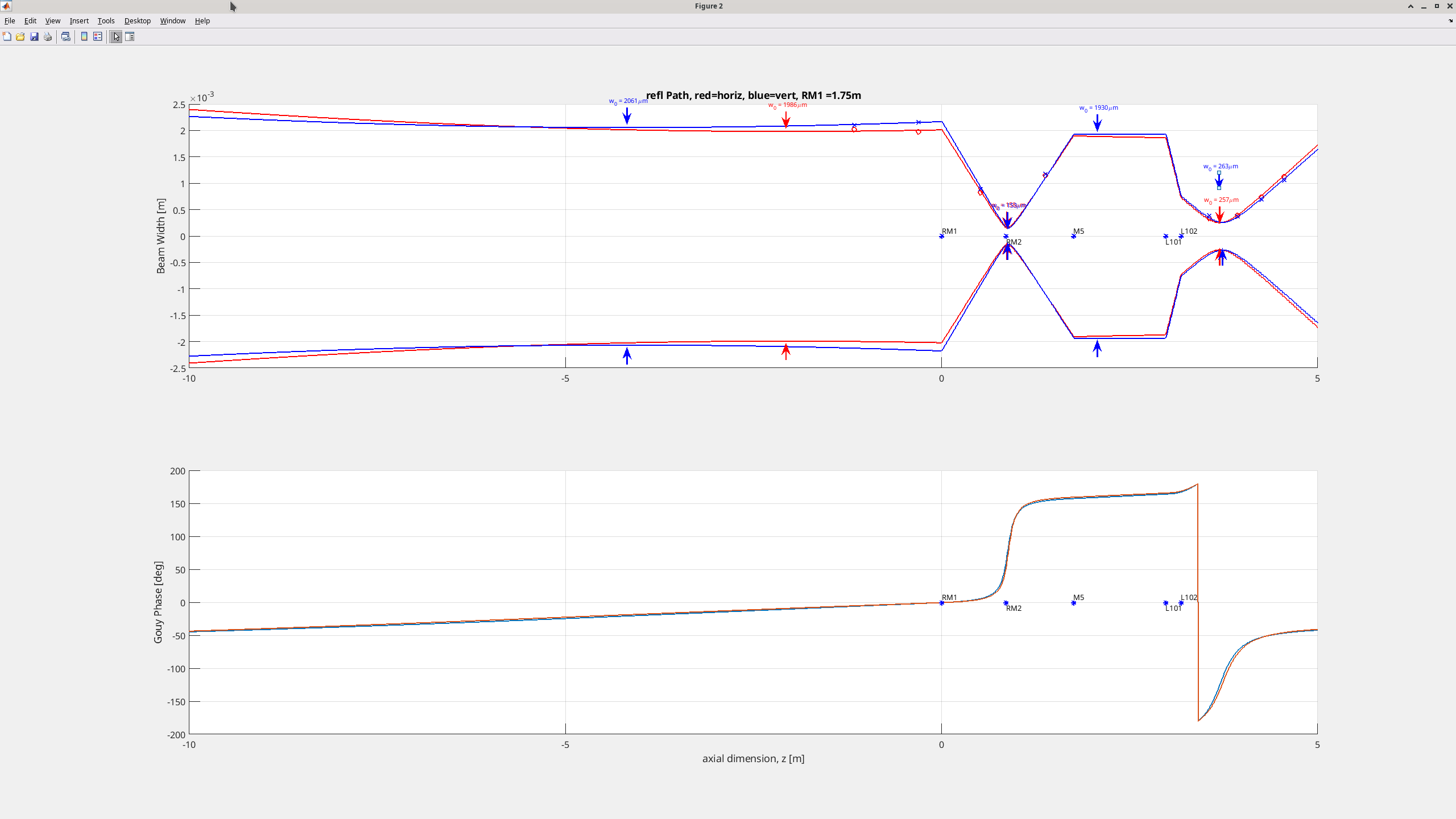
The beam path results are shown in this first plot, where RM1 and M5 RoC are set to 1.7 m (as in spec). The astigmatism shows waists upstream of RM1 are separated by over 1 m. I color coded traces for horizontal and vertical, and o's and x's mark the measurement locations that were fit. However, I didn't include any angle of incidence in this calculation, which would probably adjust this result slightly (it appears the AOIs are probably 10 degrees or less). For completeness, I also included the results if we assume the RM1 and M5 RoC are 1.75 m, in this plot. In this result, the upstream waists are 2 m apart.
For both fits, I used the qs that Paul and Lisa calculated as the seed qs in T1300960. Sheila and I are in the process of confirming these qs by doing the beam propagation of the IMC waist to the HAM1 table. To clarify, a la mode forces you to supply some input seed beam for propagation and fitting, so I supplied this seed, since you want to use something you think is pretty close to the true value. However, it only uses that seed as a starting point and then fits the data points supplied. The resulting incoming beam to RM1 is fit as:
horizontal = waist 1.60 mm, 6.4 m upstream of RM1 (RM1 RoC 1.7 m)
vertical = waist 1.52 mm, 7.5 m upstream of RM1 (RM1 RoC 1.7 m)
or
horizontal = waist 1.99 mm, 2.07 m upstream of RM1 (RM1 RoC 1.75 m)
vertical = waist 2.06 mm, 4.2 m upstream of RM1 (RM1 RoC 1.75 m)
The code I wrote is attached to this alog. Below are tables of the beam profile measurements (copied from 84230), and the specs of the mirrors and lenses I used.
| Measurement location | Distance (relative to RM1), mm | wx [um] | wy [um] |
| before RM1 | -1162 | 4038.9/2 | 4206.2/2 |
| before RM1 | -314 | 3950.6/2 | 4315.0/2 |
| between RM1 and RM2 | 511 | 1650.9/2 | 1805.1/2 |
| after RM2 | 1377 | 2304.8/2 | 2335.9/2 |
| WFS A | 3460 + 94 | 670.26/2 | 778.95/2 |
| WFS B | 3460 + 466.5 | 793.73/2 | 711.29/2 |
| downstream of sled 1 | 3460 + 788.5 | 1484.15/2 | 1387.24/2 |
| downstream of sled 2 | 3460 + 1092.5 | 2253.78/2 | 2119.24/2 |
| Component | Location (relative to RM1), mm | Specification |
| RM1 | 0 | Rc= 1.7 m (1.75 m) |
| RM2 | 856 | Rc= -0.6 m |
| M5 | 1751 | Rc= 1.7 m (1.75 m) |
| L101 | 2977 | f = 333.6 mm |
| L102 | 3180 | f = -166.8 mm |
| Horizontal seed for starting point only | -1e-3 | q=2.8071 + 13.3724i |
| Vertical seed for starting point only | -1e-3 | q=2.5071 + 13.0988i |