Sheila and I used the thorlabs power meters to do a quick power budget along the POP and REFL paths. Just as a note, this alog from Craig and others in 2022 still holds and is probably the best authority for the REFL path.
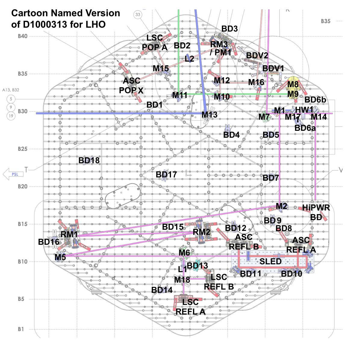
Attached is a handy cartoon with the naming convention for HAM1, see D1000313.
POP path measurements:
POP path measurements were taken in "single bounce" 10 W input. So PRM misaligned, ITMX aligned. 9.4 W was incident on IM4 trans.
Expected power to HAM1 = 9.4 W * 0.977 (IFI transmission) * 0.031 (PRM transmission) * 0.5 * 0.5 (two passes of the BS) * 229e-6 (PR2 transmission) = 16.3 uW (this assumes the reflection off the ITM is 1)
The POP beam then sees a 90/10 split at M12 (air/vac) and a 50/50 split at M15 (LSC/ASC).
| Location | Measured | Expected (how calculated) | Ratio Measured/Expected |
| After periscope | 15 uW | 16.3 uW (9.4 * 0.977 * 0.031 * 0.5 * 0.5 * 229e-6) | 0.92 |
| reflection of M12 (90/10 splitter for air/vac) | 14 uW | 14.7 uW (9.4 * 0.977 *0.031 * 0.5 * 0.5 * 229e-6 * 0.9) | 0.95 |
| transmission of M15 (just before POP ASC diode) | 0.65 uW | 0.81 uW (9.4 * 0.977 * 0.031 * 0.5 * 0.5 * 229e-6 * 0.1 * 0.5) | 0.8 |
The beam is hard to see until after the lens so these were the only measurements possible.
REFL path measurements:
These measurements were taken in two sets, with the first set at 10 W input with PRM misaligned and the second set at 2 W input with PRM aligned and ITMX misaligned.
Set 1 is single bounce with PRM misaligned and 9.4 W on IM4 trans.
Expected power to HAM1 = 9.4 W * 0.977 * 0.031 * 0.5 *0.5 * 0.031 * 0.977 (double pass of beam splitter, PRM and IFI) = 2.15 mW (this assumes that the backward throughput of the IFI is the same as the forward throughput)
| Location | Measured | Expected (how calculated) | Ratio Measured/Expected |
| Before M14 (beam just coming to HAM1) | 2.05 mW | 2.15 mW (9.4 * 0.977 *0.031 *0.5 * 0.5 * 0.031 * 0.977) | 0.95 |
| reflection of M14 (90/10 splitter) | 1.9 mW | 1.94 mW (9.4 * 0.977 * 0.031 *0.5 * 0.5 * 0.031 * 0.977 * 0.9) | 0.98 |
| transmission of M17 (first 50/50) | 0.1 mW | 0.11 mW (9.4 * 0.977 * 0.031 *0.5 * 0.5 * 0.031 * 0.977 * 0.1 * 0.5) | 0.91 |
| transmission of M1 (second 50/50) | 40 uW |
53.9 uW (9.4 * 0.977 * 0.031 *0.5 * 0.5 * 0.031 * 0.977 * 0.1 * 0.5 * 0.5) |
0.74 |
Set 2 is single bounce with PRM aligned and 2 W input, so 1.9 W on IM4 trans.
Expected power to HAM1 = 1.9 W * 0.977 (IFI throughput) * 0.97 (PRM reflection) * 0.977 (IFI throughput)= 1.76 mW
| Location | Measured | Expected (how calculated) | Ratio Measured/Expected |
| before M2 (third 50/50 splitter) | 64 mW** | 44 mW (1.9 W * 0.977 * 0.97 * 0.977 * 0.1 * 0.5 * 0.5) | 1.45 |
| before M6 (LSC/ASC splitter) | 14 mW | 22 mW (1.9 W * 0.977 * 0.97 * 0.977 * 0.1 * 0.5 * 0.5 * 0.5) | 0.64 |
| transmission M6 (50/50 LSC/ASC splitter) | 7 mW | 11 mW (1.9 W * 0.977 * 0.97 * 0.977 * 0.1 * 0.5 * 0.5 * 0.5 * 0.5) | 0.64 |
| reflection of M18 (50/50 LSC A/B splitter) | 3.5 mW | 5.5 mW (1.9 W * 0.977 * 0.97 * 0.977 * 0.1 * 0.5 * 0.5 * 0.5 * 0.5 * 0.5) | 0.64 |
| transmission of M18 (50/50 LSC A/B splitter) | 3.5 mW | 5.5 mW (1.9 W * 0.977 * 0.97 * 0.977 * 0.1 * 0.5 * 0.5 * 0.5 * 0.5 * 0.5) | 0.64 |
** we made this first measurement as a quick check to see what power was going to the other side of the table, but clearly something is wrong with it! Maybe I transposed a number?
While there is clearly a discrepancy between what light we measure vs expect at M6, all the splitting ratios after seems to make sense. Craig calculated what the true splitting ratios for M14, M17 and M1 in alog 63510. None of these optics have changed. The splitting ratios are as follows:
M14 trans = 0.0756
M17 trans = 0.5072
M1 trans = 0.5295
If I update the calculations of the REFL path using those numbers, I get the following, with bolded values noting which ones have changed:
| Location | Measured | Expected (how calculated) | Ratio Measured/Expected |
| Before M14 (beam just coming to HAM1) | 2.05 mW | 2.15 mW (9.4 * 0.977 * 0.031 *0.5 * 0.5 * 0.031 * 0.977) | 0.95 |
| reflection of M14 (90/10 splitter) | 1.9 mW | 1.99 mW (9.4 * 0.977* 0.031 *0.5 * 0.5 * 0.031 * 0.977 * (1-0.0756)) | 0.95 |
| transmission of M17 (first 50/50) | 0.1 mW | 0.083 mW (9.4 * 0.977 * 0.031 *0.5 * 0.5 * 0.031 * 0.977 * 0.0756 * 0.5072) | 1.2 |
| transmission of M1 (second 50/50) | 40 uW |
43.8 uW (9.4 * 0.977 * 0.031 *0.5 * 0.5 * 0.031 * 0.977 * 0.0756 * 0.5072 * 0.5295) |
0.91 |
| Location | Measured | Expected (how calculated) | Ratio Measured/Expected |
| before M2 (third 50/50 splitter) | 64 mW** | 35.7 mW (1.9 * 0.977 * 0.97 *0.977 * (0.0756) * 0.5072 * 0.5295) | 1.8 |
| before M6 (LSC/ASC splitter) | 14 mW | 17.8 mW (1.9 * 0.977 * 0.97 *0.977 * (0.0756) * 0.5072 * 0.5295 * 0.5) | 0.79 |
| transmission M6 (50/50 LSC/ASC splitter) | 7 mW | 8.9 mW (1.9 * 0.977 * 0.97 *0.977 * (0.0756) * 0.5072 * 0.5295 * 0.5 * 0.5) | 0.79 |
| reflection of M18 (50/50 LSC A/B splitter) | 3.5 mW | 4.46 mW (1.9 * 0.977 * 0.97 *0.977 * (0.0756) * 0.5072 * 0.5295 * 0.5 * 0.5 * 0.5) | 0.78 |
| transmission of M18 (50/50 LSC A/B splitter) | 3.5 mW | 4.46 mW (1.9 * 0.977 * 0.97 *0.977 * (0.0756) * 0.5072 * 0.5295 * 0.5 * 0.5 * 0.5) | 0.78 |
Following up to add that Sheila and I recently checked the POP calibration in 82656, and it appeared we were missing about 15% of the power we expected on POP. Based on the measurements above, I can convince myself that it is possible we could have had that discrepancy, due to extra loss in the path into/on HAM1. However, these measurements do not exactly recreate that scenario because before we had a 95/5 at M12 and an HR at M15.