jeffrey.kissel@LIGO.ORG - posted 13:35, Monday 19 May 2025 - last comment - 14:37, Monday 19 May 2025(84462)
Physical Check of Actuation Sign for RM1 and RM2 as they Currently Stand; OK for doors, but we've got work to do.
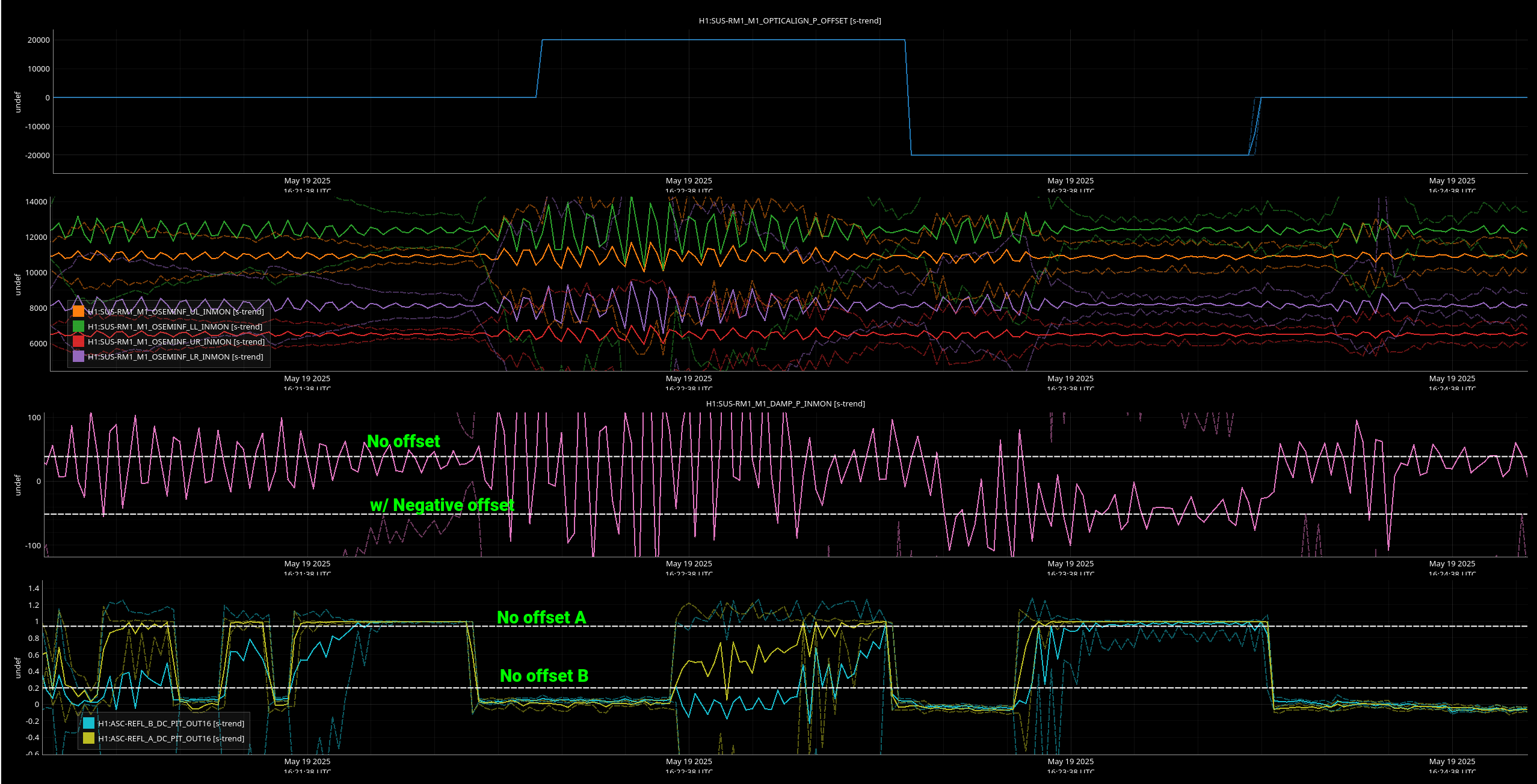
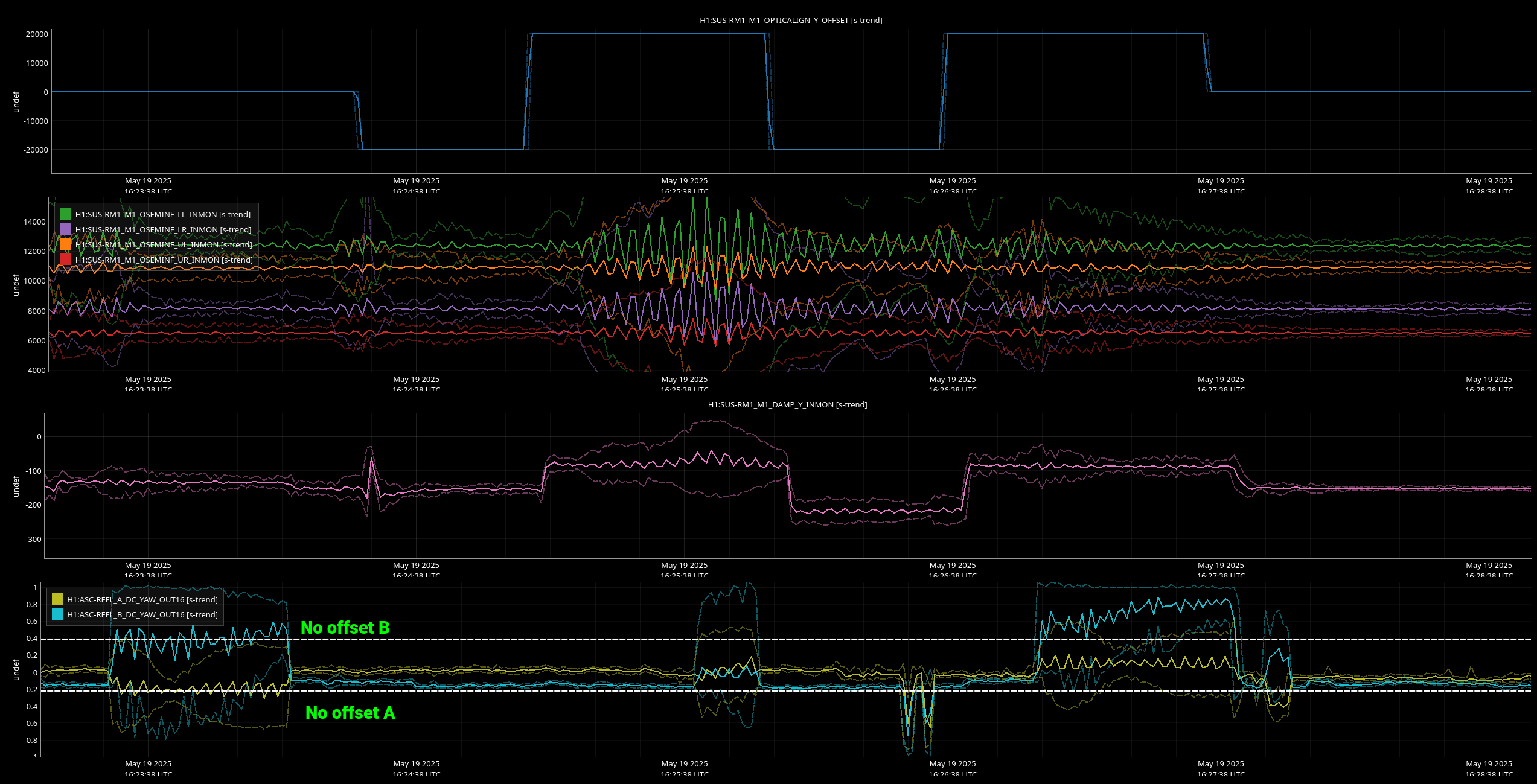
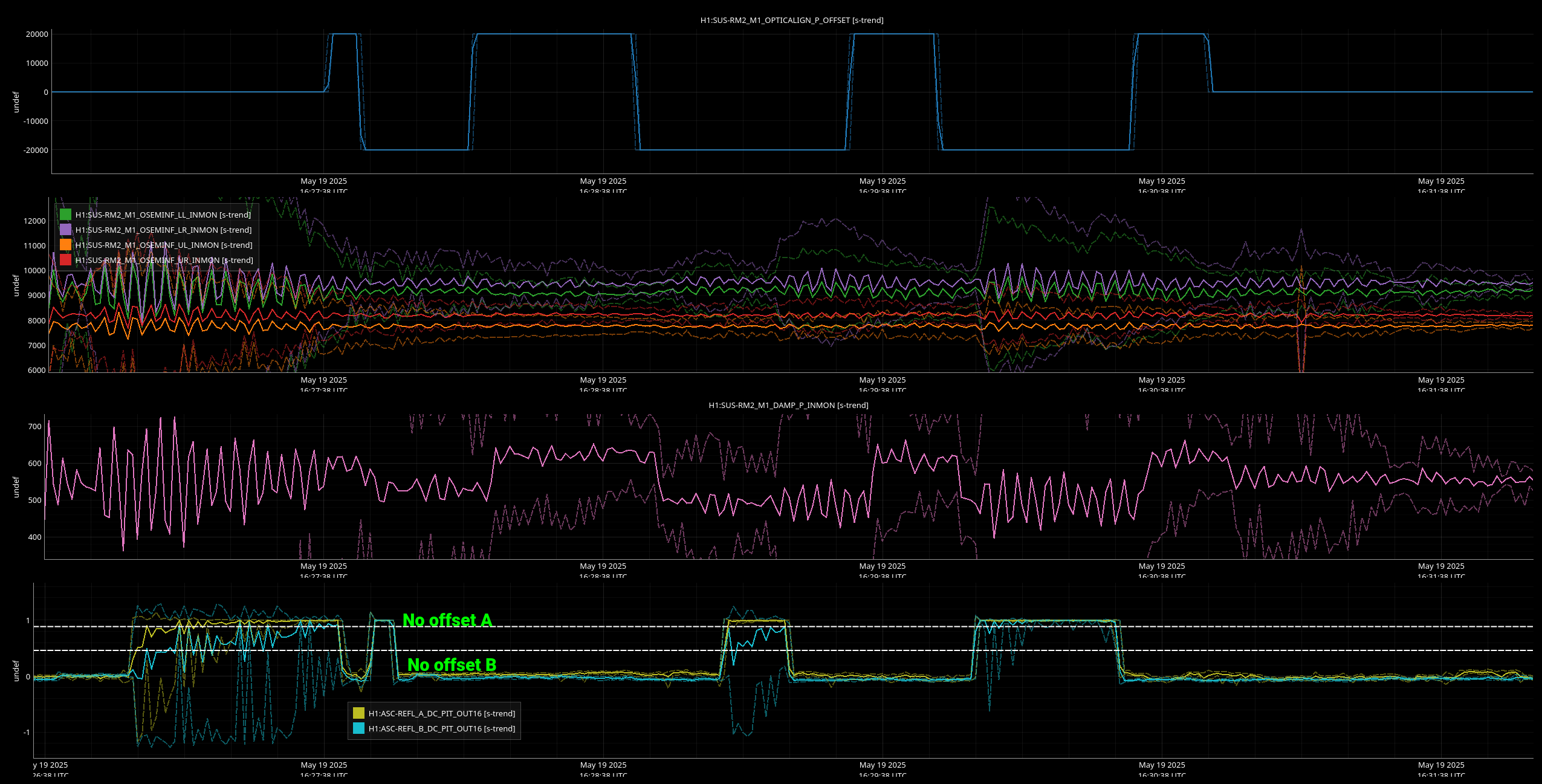
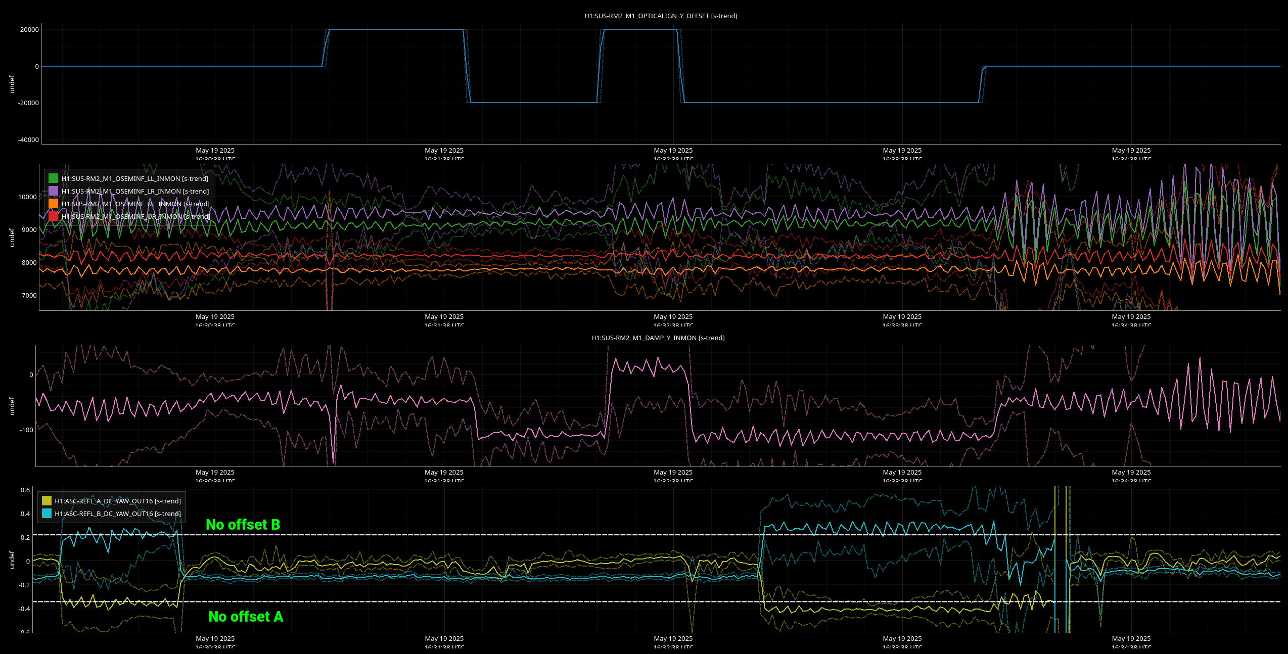
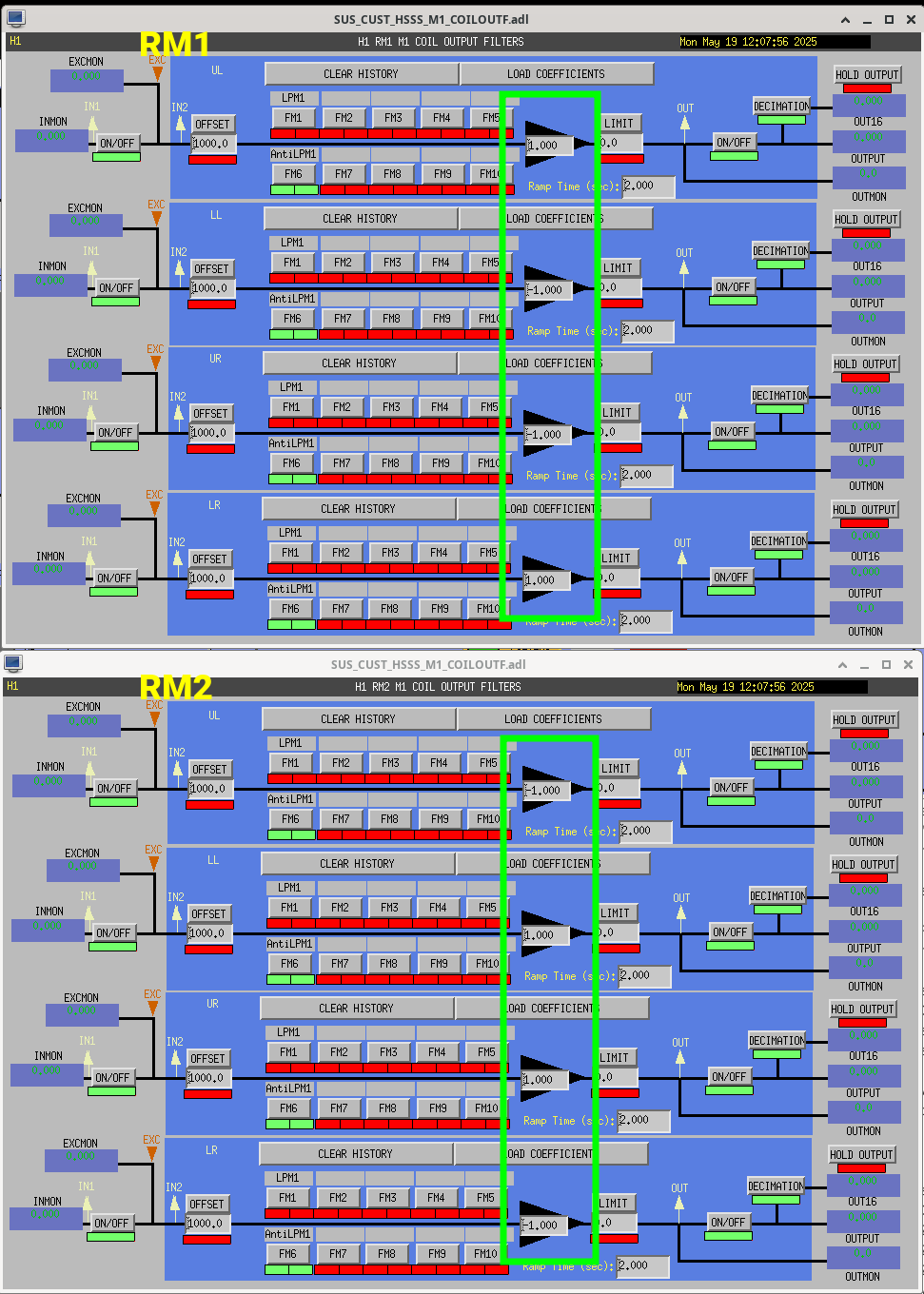
R. Kumar, C. Compton, J. Kissel
(Using Cartoon from other files of D1000313-v19)
(Following sign conventions from T1200015)

Given the sign confusion of the RMs (LHO:84289), I wanted a physical, with-our-eyeballs, confirmation of how the RMs deflect the beam under different alignment offsets given the current state of the system while we still had doors off HAM1. Using the REFL beam as our optical lever, we drove +/-20000 [ct] alignment offsets into each suspensions H1:SUS-RM[1,2]_M1_OPTICALIGN_[P,Y]_OFFSET, and watched the displaced beam downstream of the optic. Rahul was in chamber with the card and his eyeballs, Camilla was chamberside in view of the card as a second set of eyeballs to confirm, and I was driving with a CDS laptop and taking notes. Detailed blow-by-blow and raw convention-free data can be found in the attached text file.

Conclusions (all statements made with "Today," preceding the statement):
(0) We checked that
  On the actuation side,
    (a) H1:SUS-RM[1,2]_M1_OPTICALIGN_[P,Y]_GAINs are all positive, at +1.0;
    (b) The sign of the pitch and yaw elements of the EUL2OSEM matrices for both RM1 and RM2 match convention;
    (c) There's no sneaky sign flop in the *filters* of the COILOUTF banks, i.e, in none of the "LPM1" or "AntiLPM1" filter modules (see (1) below for statement on sign of gains)
  On the sensor side
    (d) The raw ADC counts for both RM1 and RM2 are positive, as expected after the cable swap, and per a normal OSEM sensor;
    (e) The sign of the OSEMINF bank gains are all positive values close to +1.0, as expected for a standard OSEM sensor chain;
    (f) There's no sneaky sign flip in the *filters* of the OSEMINF banks, i.e. in none of the "10:0.4", "to_um," or "comb60" filter modules
    (g) The sign of pitch and yaw elements of the OSEM2EUL matrices are the correct transpose (in the mathematical sense) of the EUL2OSEM matrices, so they match convention

(1) the COILOUTF gains are set as they were reverted to their "been like this forever value" on May 6th LHO:84289, with
    (a) RM1 obeying convention (UL, LL, UR, LR = +, -, -, +) and
    (b) RM2 disobeying convention (UL, LL, UR, LR = +, -, -, +).

(2) RM1 displaces the beam per convention, with a
    (a) positive pitch offset displacing the downstream beam down and
    (b) positive yaw offset displacing the beam in +Y (IFO Cartesian coordinates) i.e. rotating RM1 in +RZ, or +yaw,
    at RM2,

(3) RM2 displaces the beam against convention,
    (a) positive pitch offset displacing the downstream beam up and
    (b) positive yaw offset displacing the beam also +Y (IFO Cartesian coordinates) i.e. rotating RM2 in -RZ, or -yaw,
    at M5,

(4) Under these displacements,
    (a) the RM1 OSEM sensor sign agrees with the physical displacement:
        (i) positive requested pitch shows up as more positive pitch OSEM sensor value,
        (ii) positive requested yaw shows up as more positive yaw OSEM sensor value,
    (b) the RM2 OSEM sensor signs disagrees with the physical displacement:
        (i) positive requested pitch displaces the beam up (negative pitch), so the optic has physically tilted up in negative pitch, but the OSEM reads this as positive pitch
        (ii) positive request yaw displaces the beam in -RZ (negative yaw), so the optic has physically rotated in negative yaw, but the OSEM reads this as positive yaw.

In each of the attach trends of the test -- RM1 PIT, RM1 YAW, RM2 PIT, and RM2 YAW -- that show
    - The digitally requested alignment offset
    - The OSEMINF raw ADC channels (just to show that these are all positive now, after the cable work discussed in LHO:84027; you can't actually see the displacement)
    - The projected Euler basis OSEM sensors
    - The REFL WFS DC QPD signals (these didn't turn out to be that useful because we didn't take care to let the beam settle at each alignment, and predicting what the sign of the measured beam spot downstream of the WFS lens is not straight-forward)

All of the above conclude that
There are no sign issues in the sensor or actuator chains for RM1
Given the combination of (1)(b) and (3)(a) + (3)(b), we conclude that
There is *no* magnet polarity problems, and we *could* make RM2 actuators obey actuation convention without any hardware change.

Instead, from (4)(b)
There remains a sign issue with the OSEM *sensor* chain for RM2.

And yet, even in the face of the *difference* in RM sensor sign, (3)(a) vs. (3)(b),
With what *very* low level "does it work or not" MEDM screen viewing that we've done, *both* RMs "need" the same *positive*, +1, damping loop gain which disobeys convention.
So --
   - Why do the RM2 sensors readout opposite from physical displacement?
and
   - Why don't RM1's damping loops work with a -1.0 damping gain?

From here we need to:
(I) Compare the *phase* of now vs. old "damping loop OFF" "health check" transfer functions. If these show a sign change after the cable swap changed the OSEM sensor sign, good.
(II) Measure the amplitude spectral density of each individual OSEMs well above the data rate we typically store them; look to see if there's no giant noise features. If there is -- debug that (usually a reboot of the satamp is the first step.)
(III) If/once there's no gross electronics noise, after the dust settles in the chamber, with doors on, turn on the damping loops with +1 gain.
(IV) Measure the open loop gain transfer functions (drive M1_DAMP_EXC, measure TF of IN1/IN2), and confirm stability and appropriate amount of gain; they should look like they did when I improved the damping loop filters back in 2022. LHO:63656. Debug further if they don't.
Images attached to this report
Non-image files attached to this report

Comments related to this report
Looked into (II) here: 84468