jeffrey.kissel@LIGO.ORG - posted 12:16, Tuesday 27 May 2025 - last comment - 12:16, Tuesday 27 May 2025(84585)
RM Damping Loops Stable, but Phase Margins are Smaller; More Gain Peaking and Damped Plant is Changed
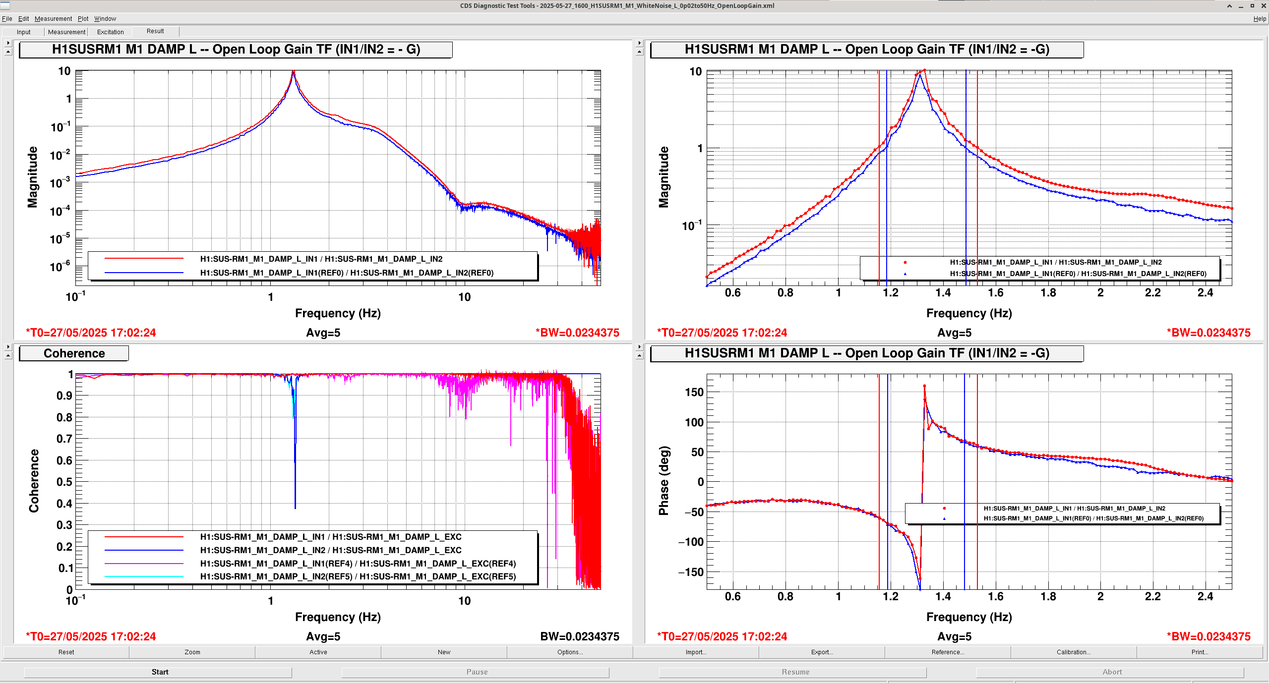
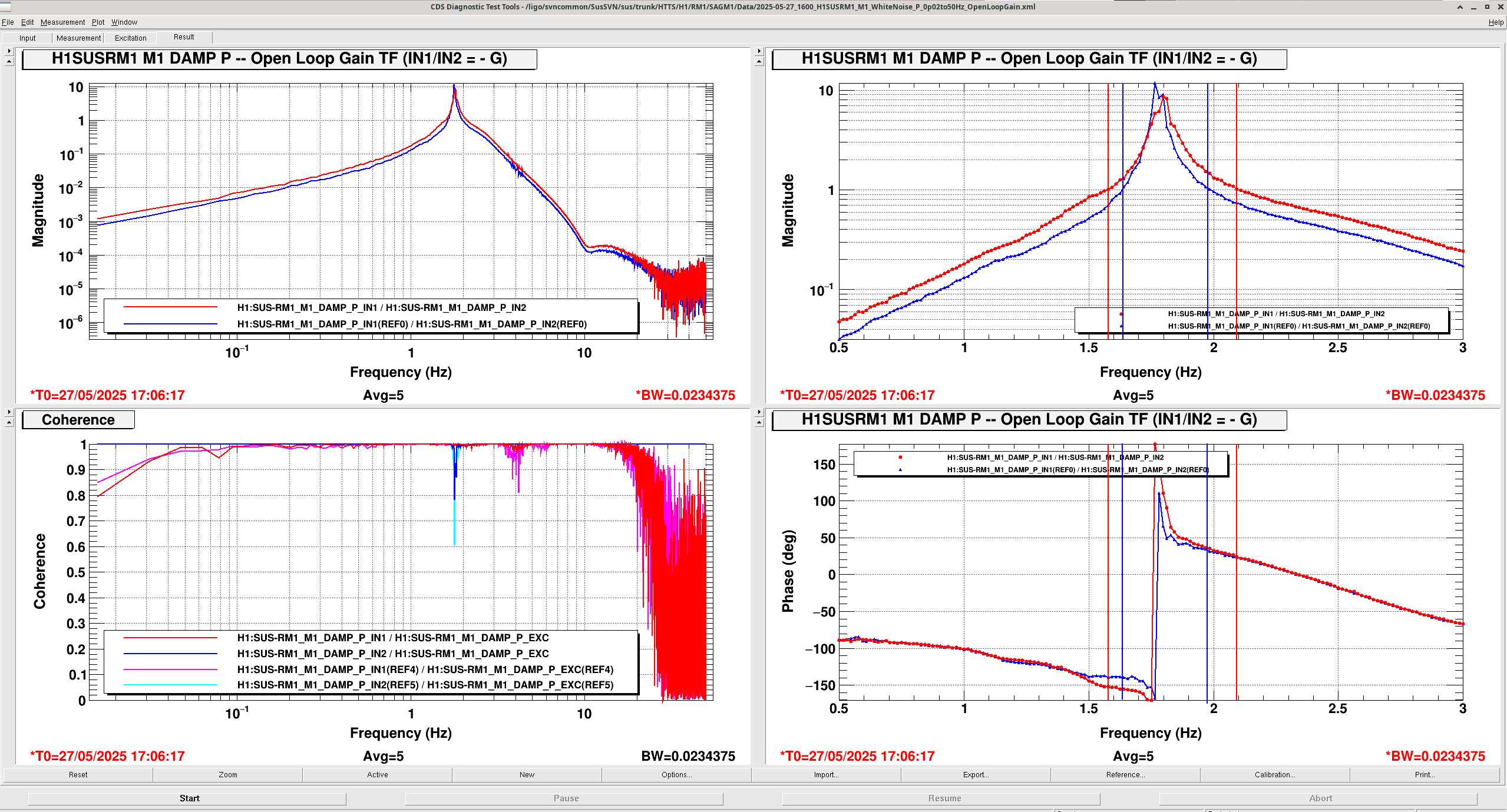
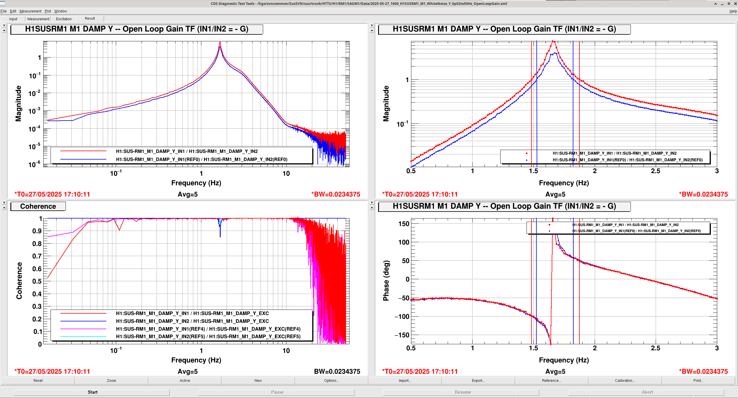
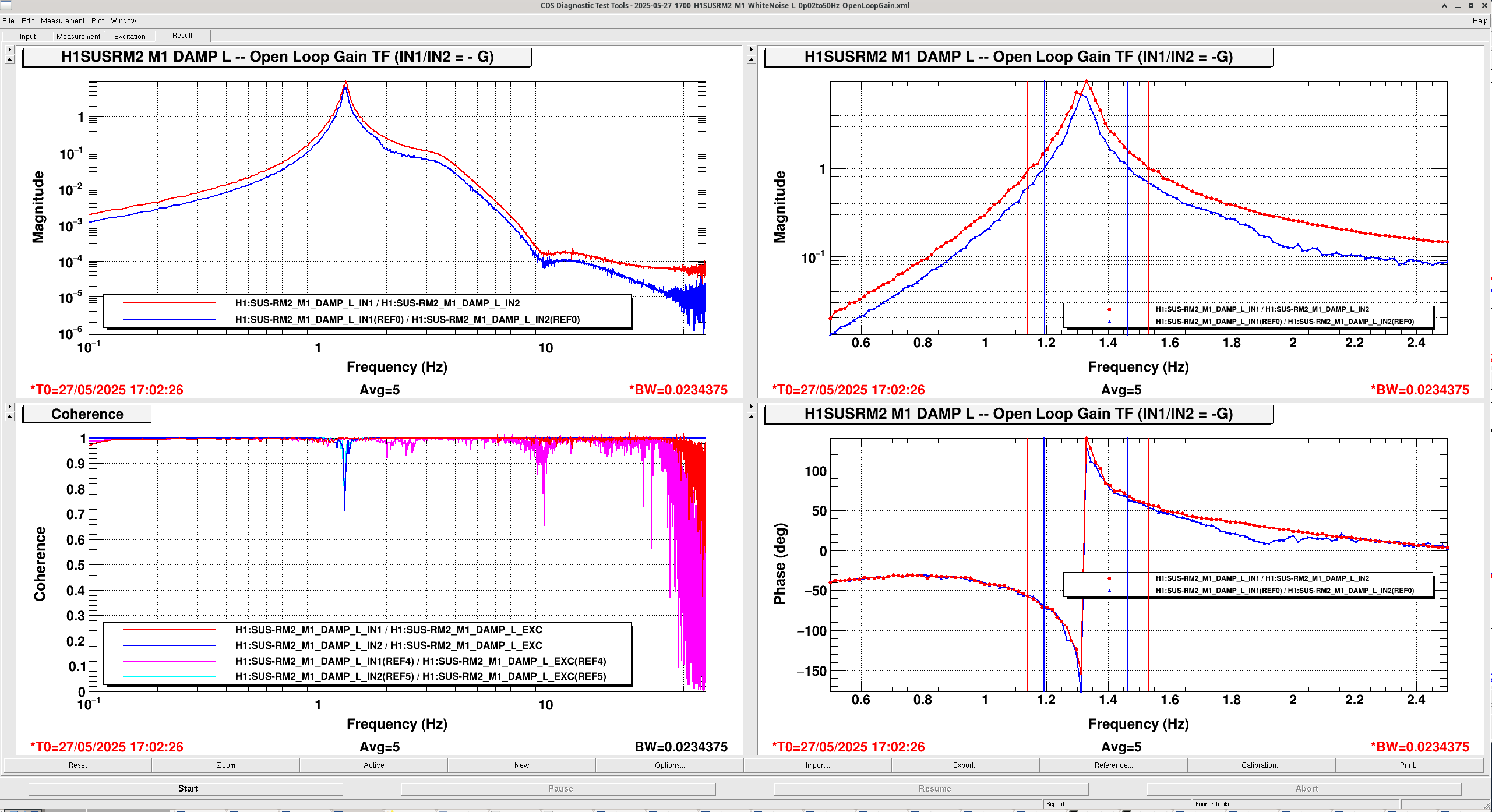
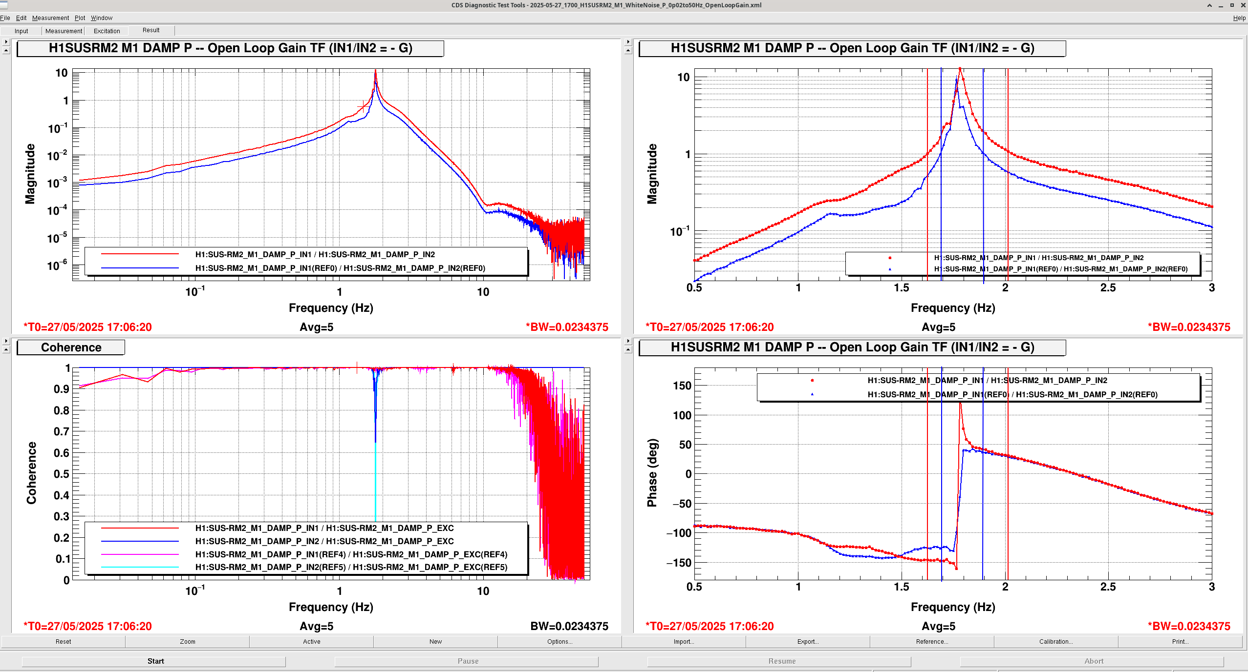
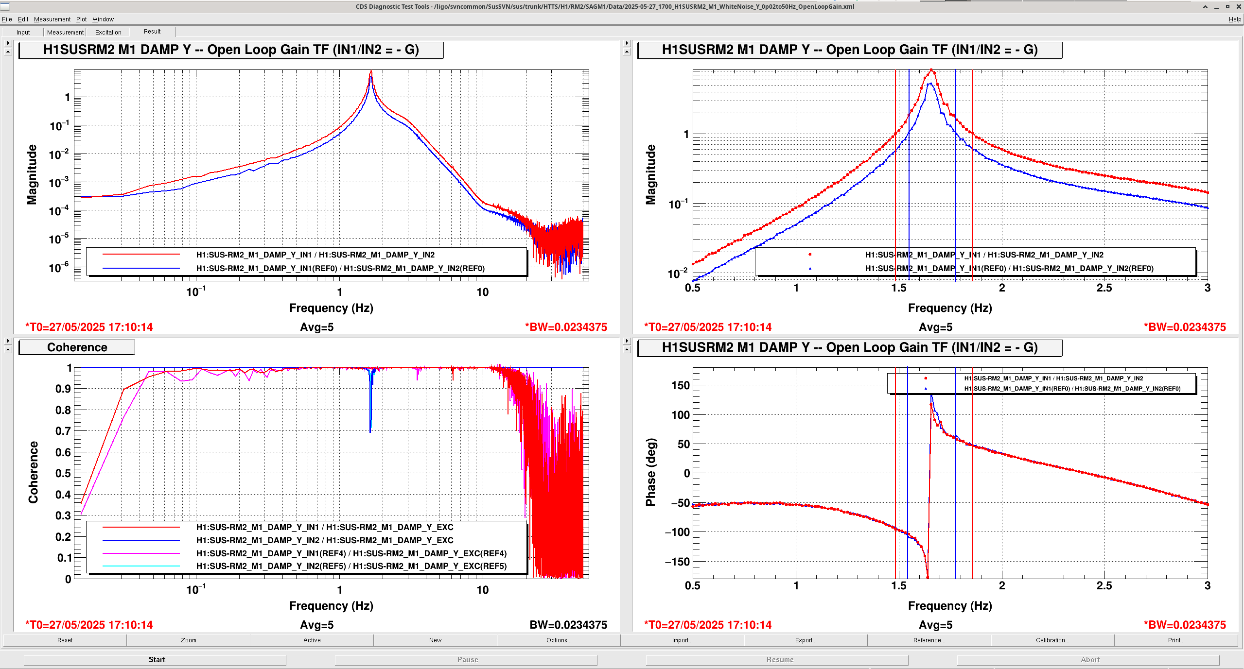
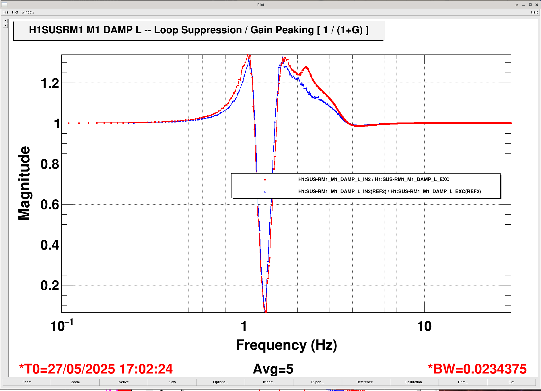
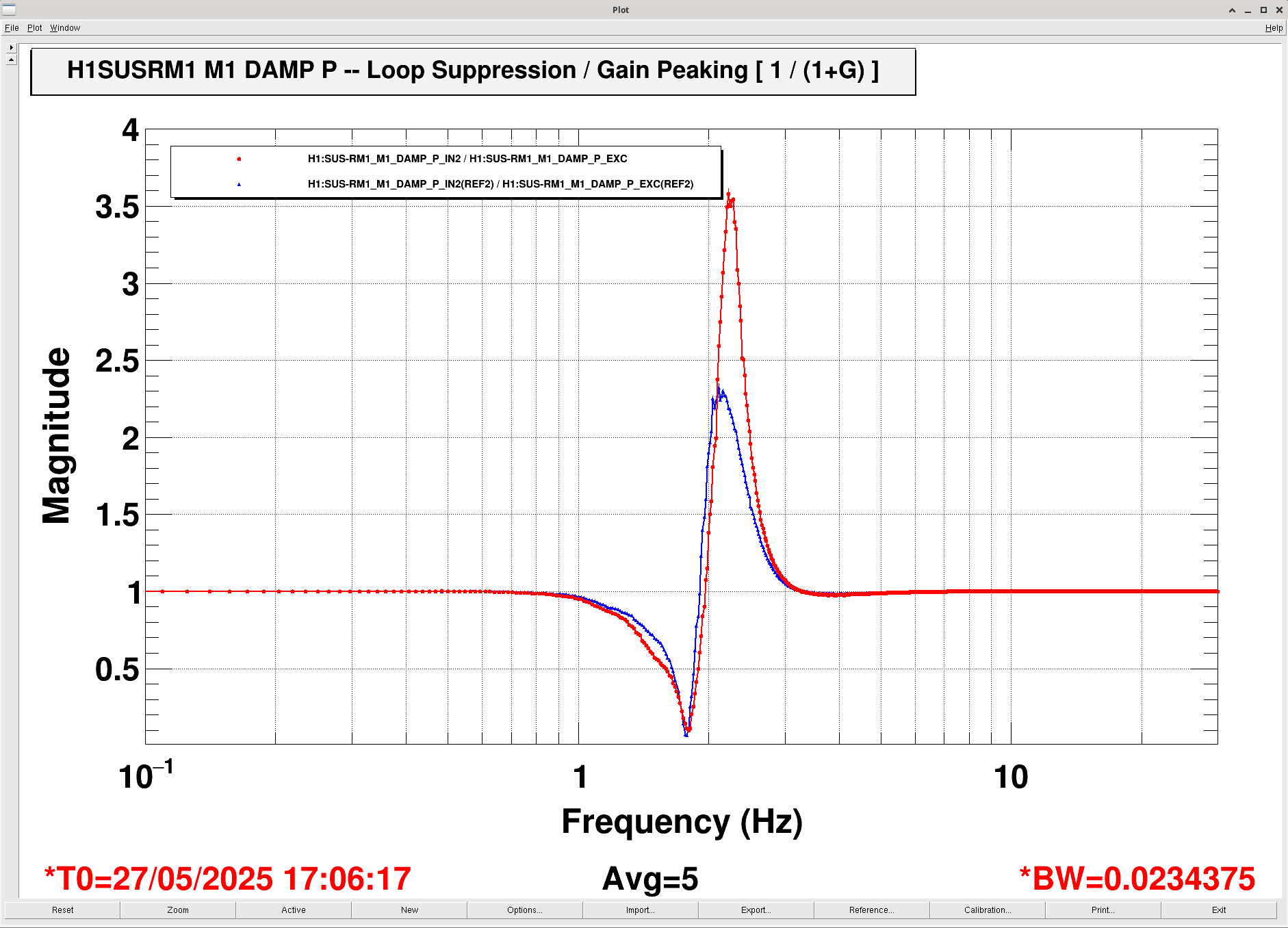
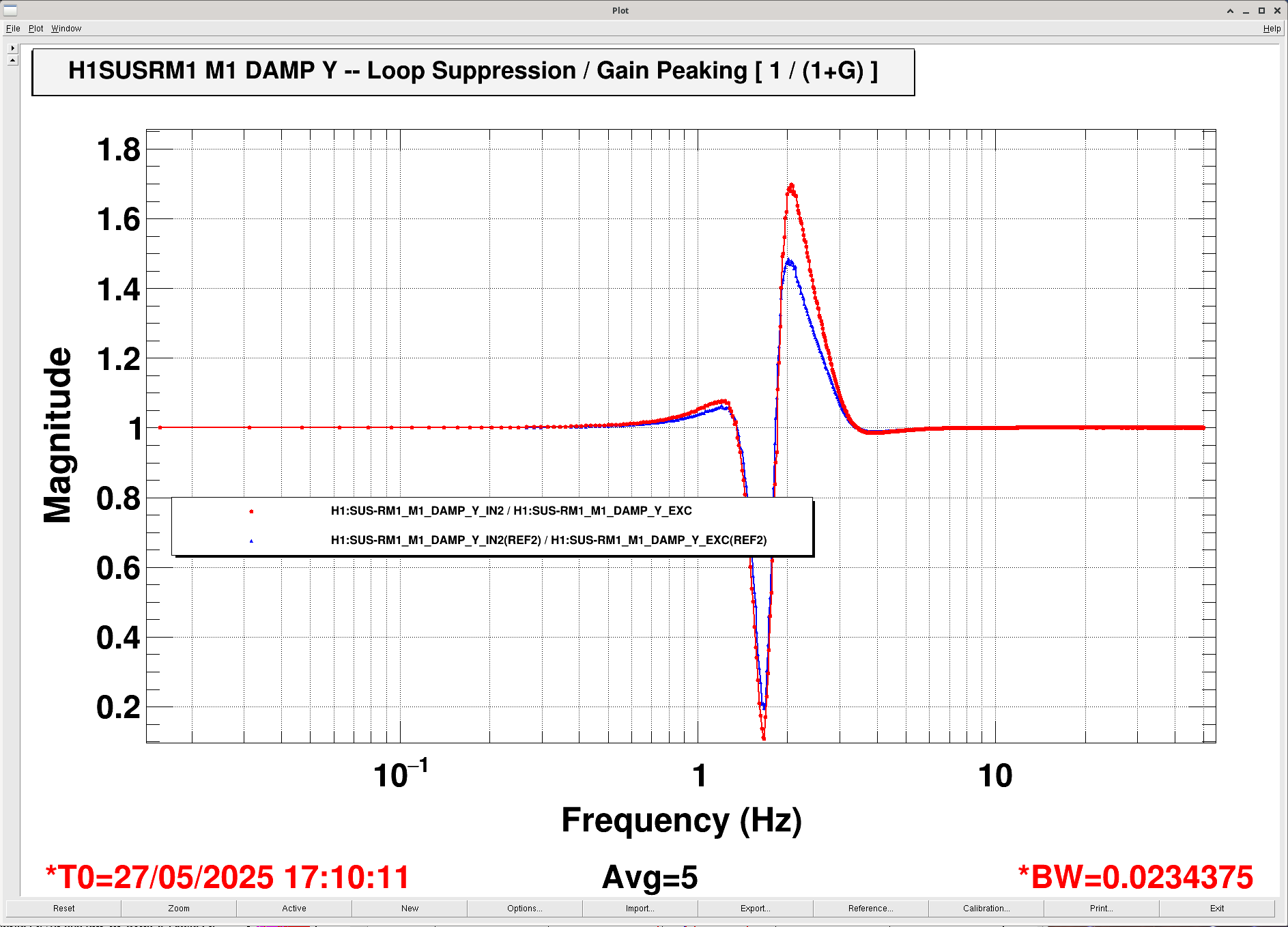
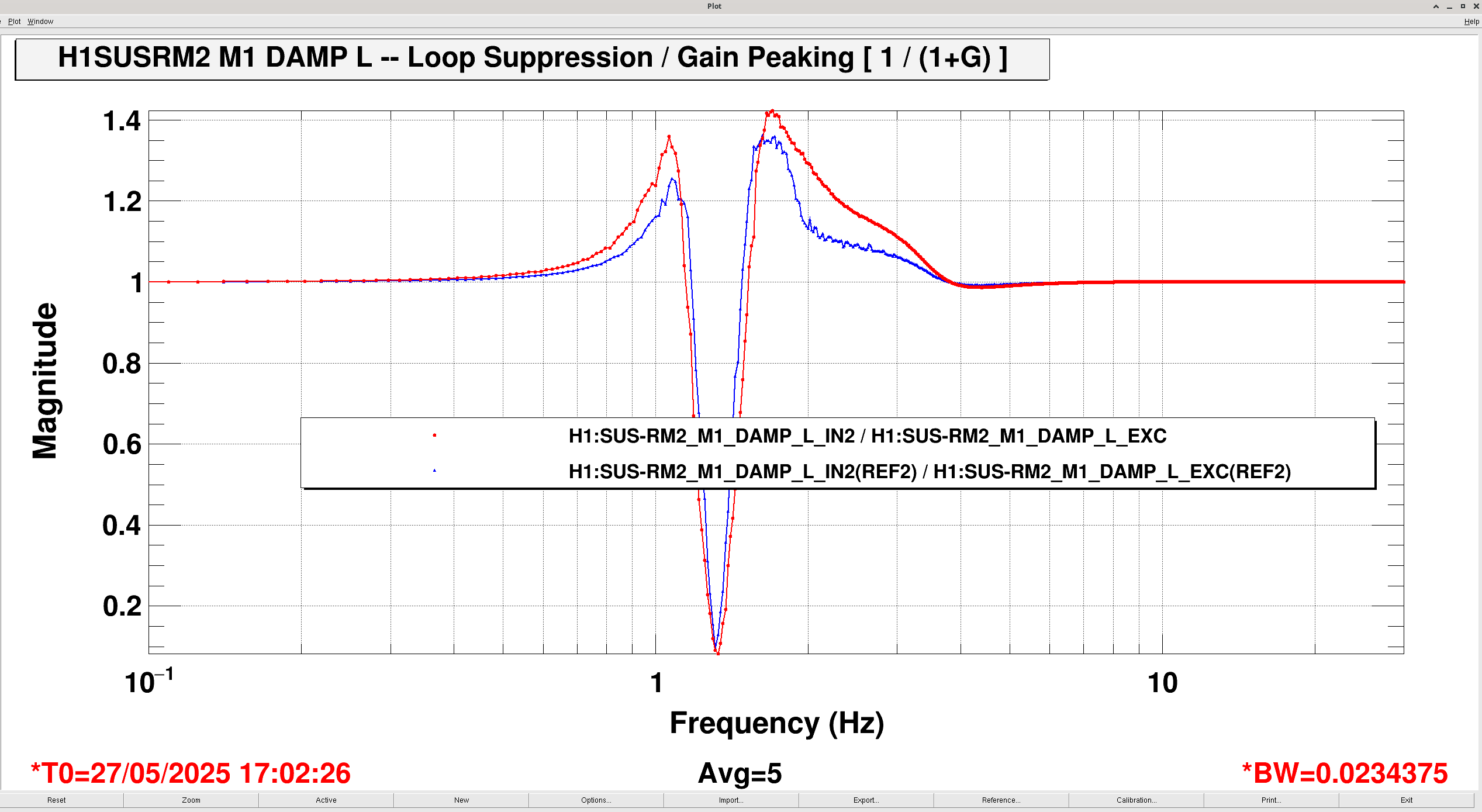
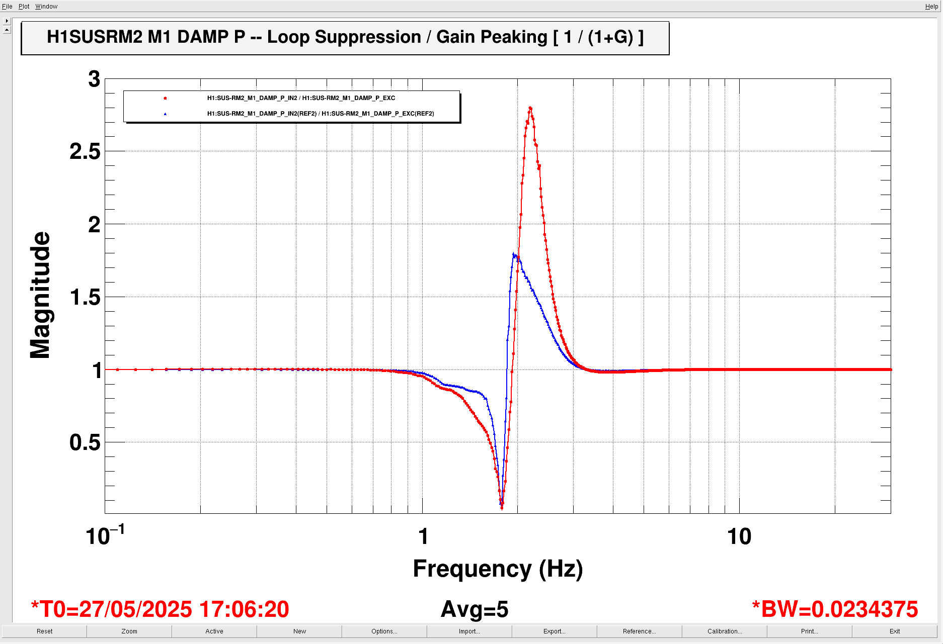
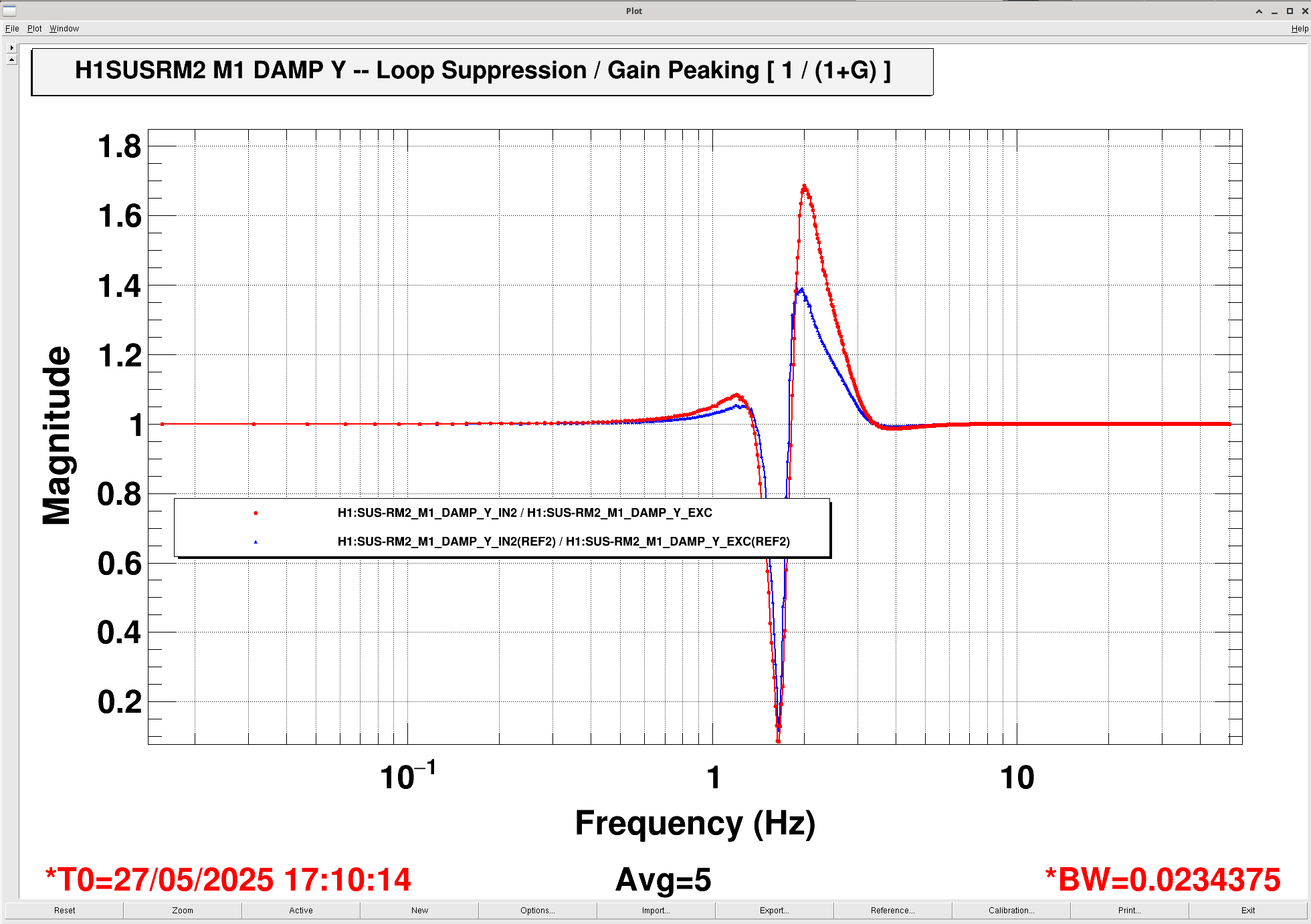
J. Kissel, O. Patane

Hearing hints that ''issues'' still remain with the RM damping loops, we continue to dig in the list of actions from LHO:84462. Here, we report the current status of the damping loop open loop gain transfer functions (and corresponding loop suppression). We several things:

(0) The open loop gain transfer functions (OLG TF, or just  G) confirm that the damping loops are stable, and regardless of the individual sign quirks of the sensors and/or actuators in the current analog / digital configuration (currently the same as described in LHO:84462).

(1) The OLG TF magnitudes have larger overall scale magnitude in all DOFs for both RM1 and RM2. Could be expected, as we completely removed the OSEMs and re-centered them during the Apr - Jun 2025 vent (see LHO:84178).

(2) Around the UGFs, between 1 - 3 Hz, the OLG TF's frequency response has changed dramatically. I'm attributing this to the dramatic change in magnitude of the cross-coupling between DOFs -- see pages 4 thru 9 of RM1 and RM1 ''health check'' undamped plant transfer functions, P, from LHO:84543. Also expected because we completely removed the OSEMs and re-centered them. In hopes to investigate the magnet polarity in the actuator, we also grabbed the flag/magnet system and tried to remove those; so it's also quite possible that the also changed position / alignment of the flag/magnet changed too (even though they couldn't completely remove it), augmenting the cross-coupling.

For suspensions "so simple" we usually try our hardest to ignore that the plant is a full 3x3 matrix. Since the beginning of time, we treat the damping loop plants as a diagonal matrix such that we can treat each DOF as a SISO loop and use an independent controller for each DOF. But clearly there is MIMO action going on here, as the diagonal TFs linked from those same plots of LHO:84543.

(3) Both (1) and (2) means that (the phase margins of G) and/or (the loop suppression transfer functions [1/ (1+G)]) have changed for the worse. If you want to quantify it with gain peaking alone, both RM1 and RM2's P to P loop suppression are the worst, increasing from magnitudes of ~1.5x to 3.5x. But, don't do that. Look at the plots.

Because the frequency response of G and [1/(1+G)] has changed ''just'' changing the overall loop gain won't return the frequency response to the expected value. It'll likely be ''good enough'' for the RM damping loops, but ...

(4) ... given that the damping loop's loop-suppression is dramatically different in the 1-3 Hz region, that also means that frequency response of the loop-suppressed plan, P/(1+G) -- which serves as the plant, P', for any *other* loops wrapped around it -- has changed. *That* could very well be the ''issues'' with the REFL WFS detector's DC centering loops -- which may have UGFs in the 1-3 Hz region.

More to come!
Images attached to this report
Comments related to this report
Table of OLG TF scale factor changes (measured at 3 Hz):
                2022-06-21     2025-05-27      Ratio (2025/2022)

    RM1   L     0.0874721       0.121968          1.3944

          P     0.173183        0.242202          1.3985

          Y     0.11679         0.153077          1.3107


    RM2   L     0.0659664       0.111818          1.6951

          P     0.112373        0.205585          1.8295

          Y     0.0873937       0.142127          1.6263

Looking at the 0.1 Hz values of the RM1 and RM2 plant measurements from LHO:84543, the ratio of undamped plant magnitudes are similar
                   2022-06-21         2025-05-27          Ratio (2025/2022)
                [m/N] or [rad/N.m]  [m/N] or [rad/N.m]
    RM1   L        0.088                 0.106               1.2045

          P      144.8                 184.1                 1.2714

          Y      136.5                 171.3                 1.2549


    RM2   L       0.068                  0.104               1.5294

          P      95.1                  162.2                 1.7056

          Y     101.1                  161.4                 1.5964


So, we'll likely drop the RM1 gain by 1.4x, and drop the RM2 gain by 1.7x.
i.e. multiply the current damping loop gain filters by 0.75x and 0.60x.