craig.cahillane@LIGO.ORG - posted 19:10, Tuesday 03 June 2025 - last comment - 20:48, Tuesday 03 June 2025(84776)
LSC sensing matrix - June 03, 2025
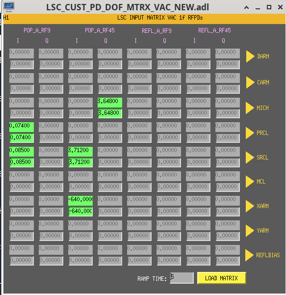
I initially tried rephasing POP 9 by hand, but moving the POP A phase by 5 degrees while we're locked using it was way too much and immediately caused a lockloss. The next lock, we found Gabriele's old LSC sensing matrix measuring software in/ligo/gitcommon/labutils/lsc_sensing_matrix/lsc_sensing_matrix.pyIt works great still. The 250 Hz line is injected using awg, and the FM5 EBS250 notch filters are still in the right location. The excitation amplitudes were 10x too strong, so we lowered them and it stopped the saturations. The resulting phases found initially are posted as the first PDF. We were pretty far off in POP 9, by 20 degrees, and by -11 degrees in POP 45. To rephase, I wrote the script to rotate the phase of POP very slowly while in lock:step_size = 11 steps = 100000 total_time = 110 init_value = ezca["LSC-POP_A_RF45_PHASE_R"] for ii in range(1,steps): small_step_size = step_size * ii / steps small_time = total_time / steps print(f"{ii}: {small_step_size}") time.sleep(small_time) ezca["LSC-POP_A_RF45_PHASE_R"] = init_value + small_step_sizeThis one worked, with only very small glitches visible in DARM. PDF 2 shows the resulting fixed LSC matrix measurement, at 60 W input power. Next, we adjusted the LSC sensing matrix according to Jenne's old instructions: alog 68547. We turned on SRCL2 and MICH2 FM5 EBS250 notch filters, and started a 250 Hz line in PRCL again. We then plotted SRCL1 and PRCL1 error signals while adjusting the POP 9 I -> SRCL intrix value by 0.005 steps, looking to minimize the appearance of the 250 Hz PRCL line sensed in SRCL. We didn't move LSC-PD_DOF_MTRX_SETTING_5_1 much: only by 0.02 from 0.10408 to 0.085, but got significant improvement, maybe a factor of 3 better. Makes some sense we'd have to adjust this after rephasing the POP diodes. The resulting LSC sensing matrix is posted as the PNG.
Images attached to this report
Non-image files attached to this report

Comments related to this report
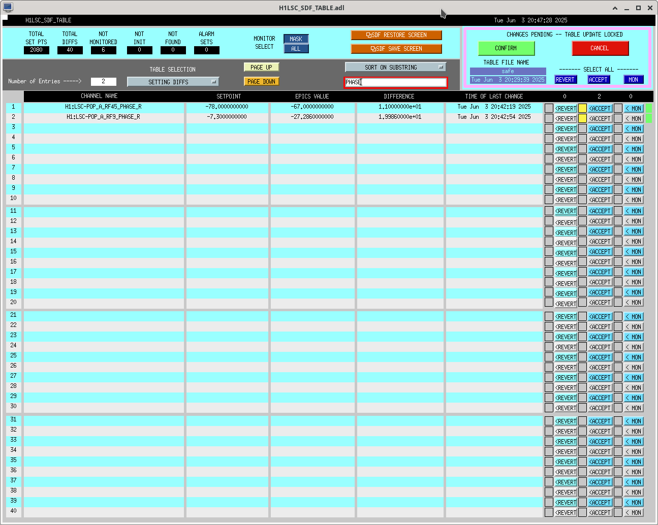
These were not SDFed but I trended and figured out what the new values are. Screenshot attached.
Images attached to this comment