Summary:
Robert's alog 84015 shows that IFO beam hitting the [+X, +Y] side barrel/edge of the BS could be coupling to DARM somehow.
Out of curiosity, we scanned the BS spot position in YAW with 2mm steps from -6mm to +6mm (measured along the BS surface, -6mm being the closest to the [+X,+Y] side barrel) while dithering the YAW angle of PR2 at 31Hz, and measured the coupling from the dither to DARM in nominal low noise.
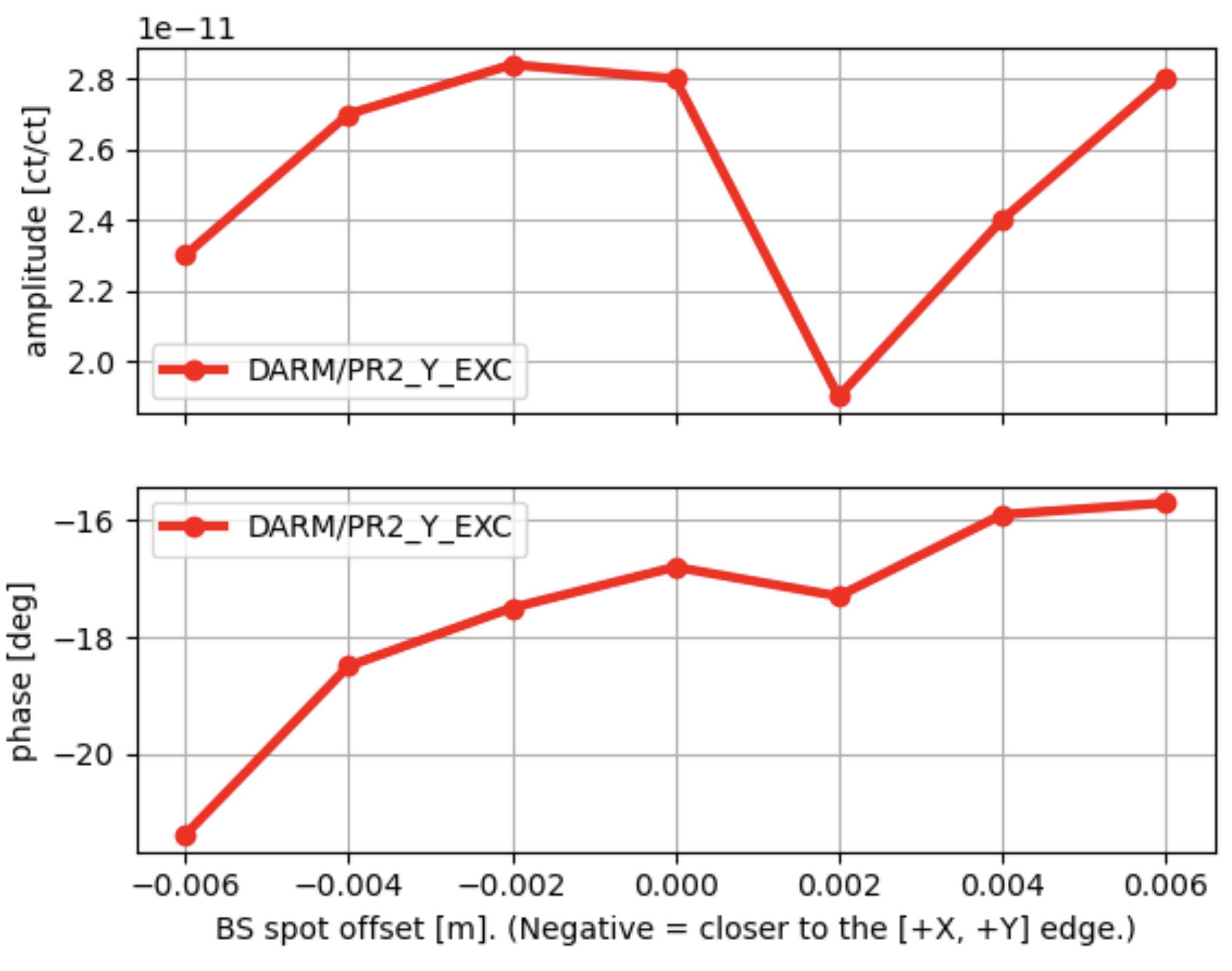
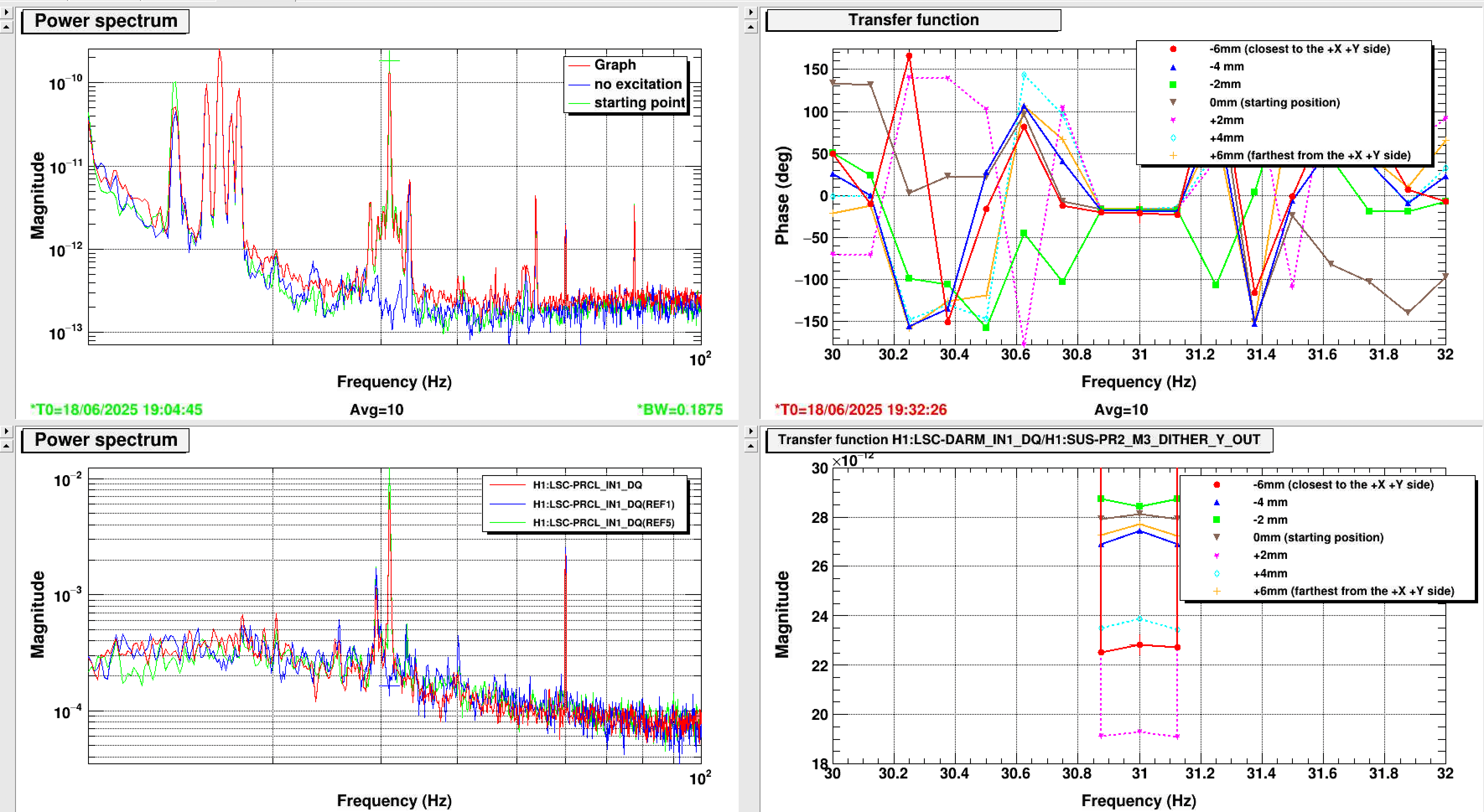
Expectation is/was that the coupling monotonically gets worse as the beam approaches the [+X, +Y] side, but we didn't see such a simple pattern. See the 1st attachment showing H1:LSC-DARM_IN1_DQ/PR2_M3_DITHER_Y_OUT TF at the dither frequency. There could be a minima at around +2mm position but there's no phase flip around that point. No clear conclusion here.
| -6mm (closest to the +X+Y side) | -4mm | -2mm | 0mm | 2mm | 4mm | 6mm (farthest from the +X+Y side) | |
| amplitude [ct/ct] | 2.3e-11 | 2.7e-11 | 2.84e-11 | 2.8e-11 | 1.9e-11 | 2.4e-11 | 2.8e-11 |
| phase | -21.4deg | -18.5deg | -17.5deg | -16.8deg | -17.3deg | -15.9deg | -15.7deg |
BS spot position and its (rough) calibration
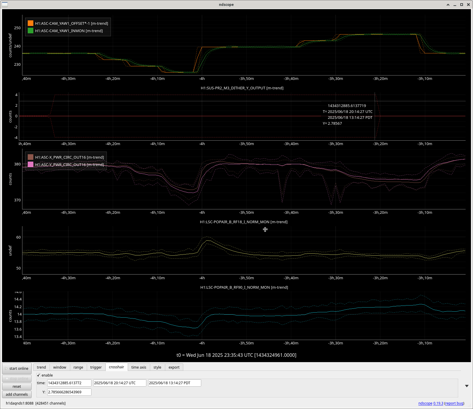
The camera servo uses the centroid position of BS spot obtained from GigE camera image in raw pixels. Nominal spot position on BS is (230, 236) for (P, Y), which is given by H1:ASC-CAM_PIT1_OFFSET=-230, H1:ASC-CAM_YAW1_OFFSET=-236.
The camera is looking at BS from -X+Y direction (WBSC2 G8 viewport). Positive increase in YAW position, which appears as a shift towards the right for the camera, means the shift in -X-Y direction on the BS surface (i.e. away from +X+Y side of the BS).
The entire frame width (640 pixels) of the GigE image is very roughly the same with the diameter of the BS (370mm nominal), so the calibration of the camera image is 370mm/640pix. Using this, +2mm step is 2mm/(370mm/640pix) ~ 3.5 pixels.
BS spot steps were given by increasing/decreasing H1:ASC-CAM_YAW1_OFFSET by integer multiple of 3.5 pixels.
Note that BS is tilted by 45 degrees relative to X and Y axis, thus +2mm on the plot means [-sqrt(2),-sqrt(2)]mm in [X,Y] direction, respectively.
We started with 0mm offset, then proceeded with -2mm, -4mm, -6mm, +2mm, +4mm and +6mm in this order. After each step, we waited until the camera servo settle, measured the transfer function at the injection frequency, and proceeded to the next step.
After we were done, spot position was set back to 0mm offset.
Injection
We made an injection of 8 counts pp at 30Hz into H1:SUS-PR2_M3_DITHER_Y_EXC, which made a huge peak in DARM. Injection was active from ~19:03 UTC to 20:14 UTC on 2025/06/18.
A2L
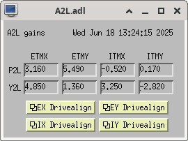
Before we started injection and before we moved the BS spot position, Ibrahim ran A2L script to set the A2L gains for quads. All measurements, even after BS spot was moved, was done with these A2L gains (4th attachment), and Ibrahim put these gains in the guardian.
A2L measurement was done with +6mm offset after all of the measurents were done, too, as we might need that data later (5th attachment).
DTT template
It's in /ligo/home/keita.kawabe/BSPOS\ VS\ jitter\ 20250618.
REF0-1: no exc, ref2-5: 0mm offset, ref6-9: -2mm, ref10-13: -4mm, ref14-17: -6mm, ref18-21: +2mm, ref22-25 +4mm, ref26-29: +6mm.