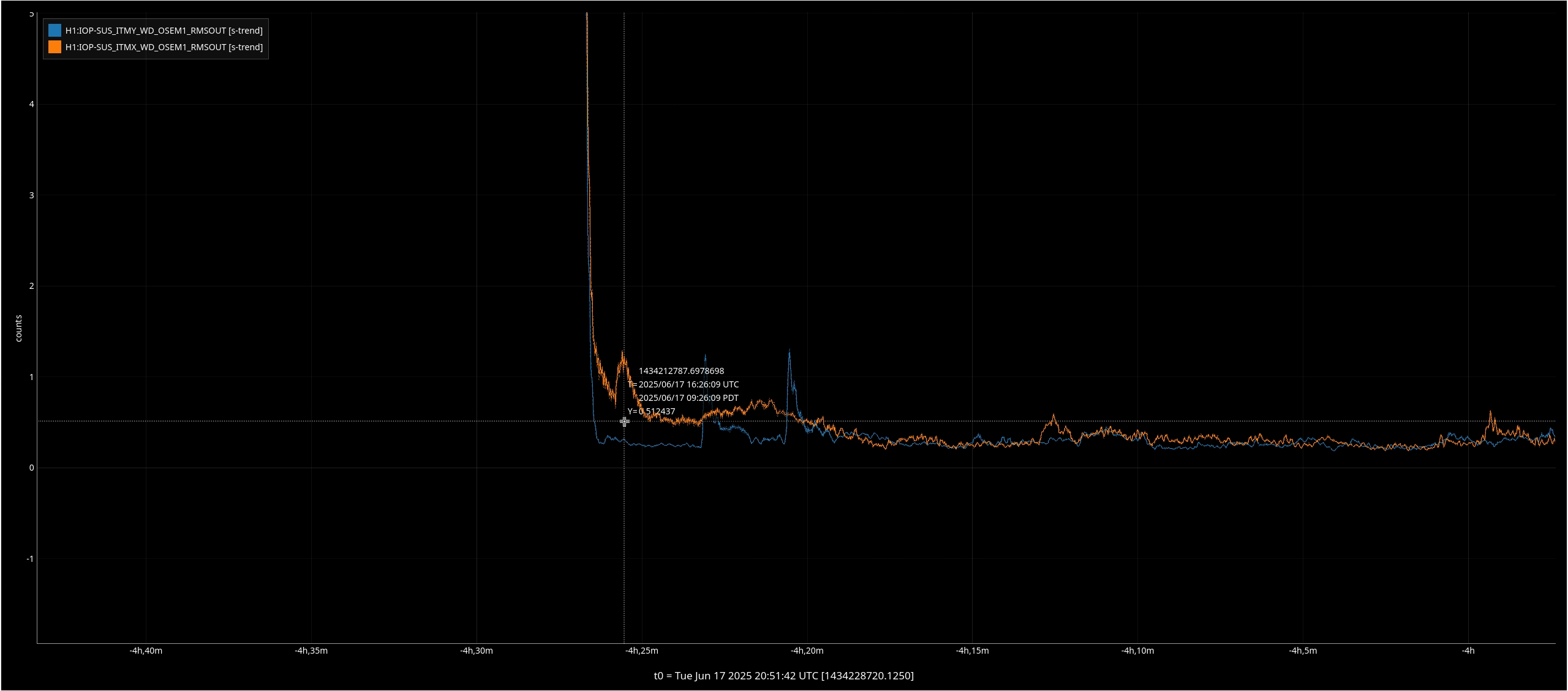
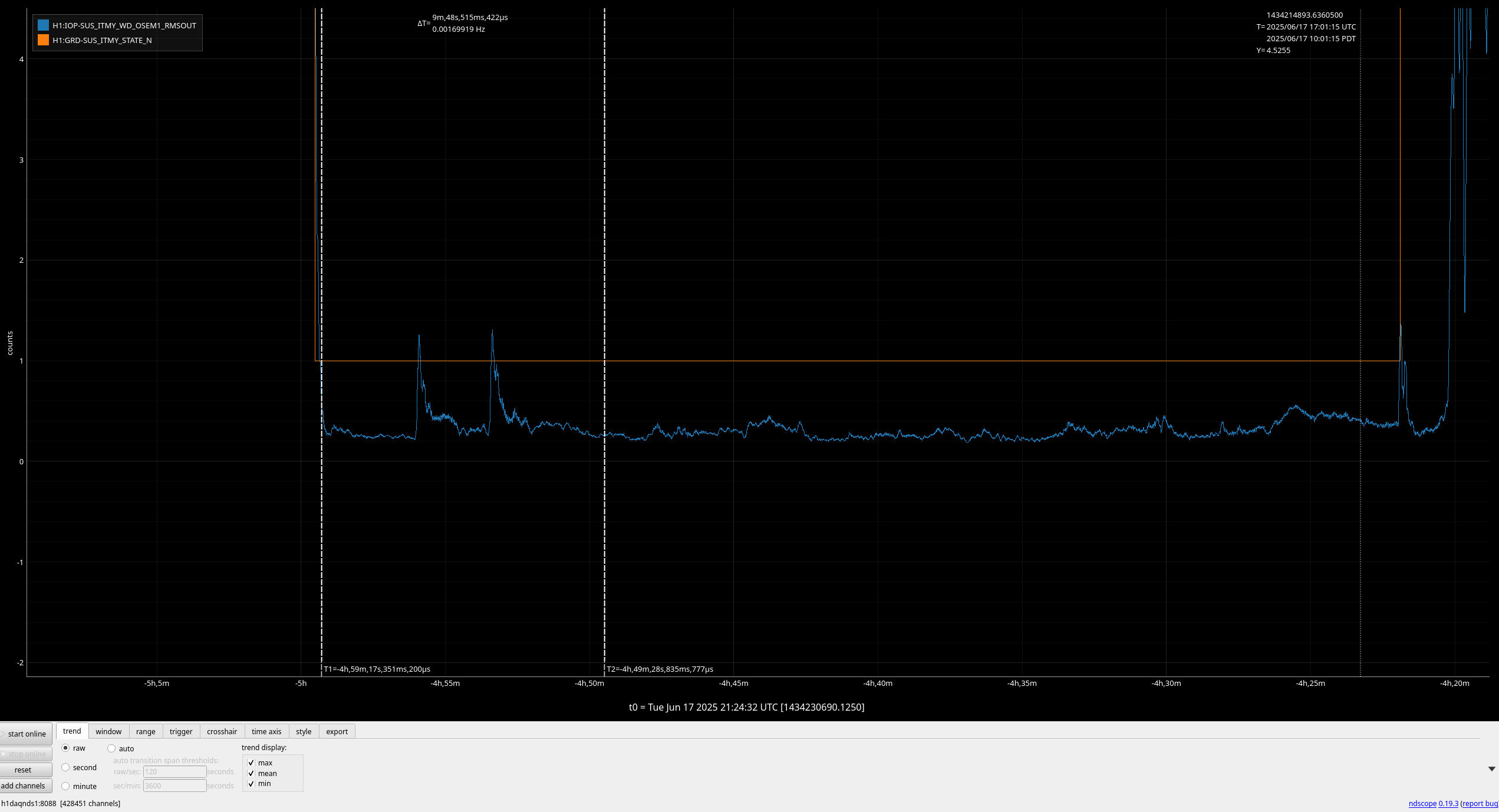
Search criteria
Section: H2
Task: TCS
Just had a couple of drops from Observing due to TCS_ITMY_CO2 guardian saying laser is unlocked and needed to find a new locking point. (Attached are the two occurrences thus far).
Closes FAMIS 28463. Last checked in alog 85690.
CO2 Trends:
HWS FAMIS:
Plots attached
TITLE: 08/05 Day Shift: 1430-2330 UTC (0730-1630 PST), all times posted in UTC
STATE of H1: Observing at 152Mpc
OUTGOING OPERATOR: Ryan C
CURRENT ENVIRONMENT:
SEI_ENV state: CALM
Wind: 12mph Gusts, 6mph 3min avg
Primary useism: 0.03 μm/s
Secondary useism: 0.09 μm/s
QUICK SUMMARY: H1 has been locked for 17 hours, but looks like there were three brief drops from observing between 11:33 and 11:40 UTC (I'm assuming SQZ-related, but will look into it). Magnetic injections are running and in-lock charge measurements will happen right after before maintenance begins at 15:00 UTC.
Lockloss happened during in-lock charge measurements, specifically during the 12Hz injection to ETMX. The lockloss tool tags IMC for this one, and it certainly looks like the IMC lost lock first, but I can't say for sure why.
The three drops from Observing that Ryan points out were actually from the CO2 lasers loosing lock, first CO2Y and then CO2X lost lock twice, all between 11:33 and 11:40UTC ~4:30amPT. Both PZTs and laser temperatures started changing ~5minutes before CO2Y last lock. Unsure what would make this happen, LVEA temperature and chiller flowrates as recorded in LVEA were stable, see attached.
Unsure of the reason for this, especially as they both changed at the same time but are for the most part independent systems (apart from shared RF source). We should watch to see if this happens again.
My initial thought was RF, but the two channels we have to monitor that both looked okay around that time. About 4 minutes before the PZTs start to move away there is maybe a slight change in the behavior of the H1:ISC-RF_C_AMP10M_OUTPUTMON channel (attachment 1), but I found a few other times it has similar output and the laser has been okay, plus 4 minutes seems like too long for a reaction like this. The pzts do show some type of glitching behavior 1-2 minutes before they start to drive away that I haven't found at other times (attachment 2). This glitch timing is identical in both laser's pzts.
I trended almost every CO2 channel that seemed worthwhile, I looked at magnetometers, LVEA microphones, seismometers, mainsmon, and I didn't find anything suspicious. The few people on site weren't in the OSB. Not sure what else to look for at this point. I'm wondering if maybe this is some type of power supply or grounding issue, but I'd expect to see it other places as well then. Perhaps places I just haven't found yet.
TCS CO2Y tripped and dropped us out of Observing at 03:58 UTC then we lost lock 2 minutes later, lockloss. The lockloss appears to have been an ETMX glitch.
Following the WIKI and TJ's instructions I went into the LVEA (TJ was my phone buddy) to restart the controller than I went into the mechanical room and reset the power supply which was reading a current and voltage of 0 when I arrived. There were no flow/chiller alarm nor RTD/IR sens alarm.
Closes FAMIS 27819. Last checked in alog 85440
CO2Y:
Before: 10.3ml
After: 10.3ml
Water Added: 0ml
CO2X:
Before: 30.4ml
After: 30.4ml
Water Added: 0ml
No water leaking in our leak detection system (aka dixie cup)
TITLE: 07/03 Day Shift: 1430-2330 UTC (0730-1630 PST), all times posted in UTC
STATE of H1: Lock Acquisition
OUTGOING OPERATOR: Oli
CURRENT ENVIRONMENT:
SEI_ENV state: CALM
Wind: 5mph Gusts, 2mph 3min avg
Primary useism: 0.01 μm/s
Secondary useism: 0.07 μm/s
QUICK SUMMARY:
H1 had (3) ~2-hr locks overnight (looks like no wake-up calls for Oli!). H1 is currently locking (just powered up to 25W). Winds stepped down at about 130amPDT (837utc).
Today is Thurs Commissioning from 8am-12pmPDT (15-19utc). H1 won't be thermalized until about 1030-11amPDT, so no calibration...hopefully H1 short locks won't be an issue for calibration where we need H1 thermalized 3hrs. Robert and Sheila will probably start their work
Just want to add a note that all three locks from last night were nearly the exact same length, 1:51, and the locklosses are all tagged with "PI monitor". A ring heater was changed yesterday, 85514, which may have caused this problem.
Additionally, each of the 3 locklosses were from PI28/29 according to VerbalAlarms (the Ring Heater change yesterday was made to address PI24 which riddled our 7hr lock for the last hour before the ultimate lockloss).
While we have been running PIMON live on nuc25, it appears the data from the lockloss hasn't been saved. The newest file in the /ligo/gitcommon/labutils/pimon/locklosses folder is from December 2024. I'm not sure what's going on. We think our problem is an 80 kHz PI, so this would be useful data to have.
Camilla, TJ, Dave:
Last Thursday 26th June 2025 alog85373 I restarted the HWS camera control code. We hoped this would improve the 2Hz noise comb in DARM. Initial results for F-Scan (observing) suggest it has not made much, if any difference.
Attached F-Scans show the spectra on sun22jun2025 and mon30jun2025. The 2Hz comb (blue squares) look unchanged.
More investigation is needed to verfiy we are indeed disabling the frame aquisition on all HWS cameras when H1 is in observation.
Looking at the HWS camera data, Dave's code was successfully stopping the HWS camera dueing NLN from 27th June, as expected 85373.
However, looking at the f-scans from the last week, the 2Hz comb was there until 3rd July but was gone on 4th July and hasn't returned since.
Nothing HWS related should have changed on the 3rd July (ops shift log 85519).
Excellent, thank you Camilla and Dave! This is very helpful.
Lockloss during commissioning at 2025-06-25 17:52UTC after over 5.5 hours Locked. Cause not known, but probably not commissioning related.
18:48 Back to NOMINAL_LOW_NOISE
Within the same ~15 seconds of the lockloss, we turned the CO2 powers down form 1.7W each to 0.9W each. In the hope of doing the thermalization tests we tried last week 85238.
We checked the lockloss today and LSC channels at the time last week we turned the CO2s down and see no glitches corresponding with the CO2 waveplate (out of vac) change, we think the lockloss was unrelated.
TJ, Camilla WP 12605, WP 12593
As HAM1 is now low enough in pressure, we removed the HAM1 +Y yellow VP covers, re-attached bellows and removed guillotines. ISCT1 was moved back into place on Friday 84850.
After TJ transitioned to Laser Hazard, we opened the ALS and PSL light pipes and turned back on the SQZ, CO2s and HWSs lasers.
After okay from VAC, IMC locked without issue, PRC and MICH alignments look good enough on AS AIR camera and we will begin realigning ISCT1 soon.
HWS servers now point to /ligo/data/hws as the data directory.
The old data directory, h1hwsmsr:/data, is now moved to h1hwsmsr:/data_old
The contents of the old directory were copied into the new directory, except H1/ITMX, H1/ITMY, H1/ETMX, H1/ETMY, under the assumption that these only contain outputs from the running processes.
HWS processes on h1hwsmsr, h1hwsmsr1, h1hwsex were stopped and restarted and are writing to the new directory.
h1hwsey had crashed previously and wasn't running. It was restarted and is also writing to the new directory
Addressed TCS Chillers (Mon [Jun2] 100-125am local) & CLOSED FAMIS #27816:
TJ, Sheila, Matt, Andrew (job shadow today), Camilla. WP12433. Table layout D1400241.
Following on from other beam profile work at the end stations 81358, Madi Simmonds models G2500646 and the ideas we had for understanding ETM mode matching better (googledoc), today we took some beam profiles of the EY ALS beam reflected of ETM HR in the HWS path.
We added a 532nm quarter waveplate downstream of the beamspiltter (ALS-M11) and tuned it to maximize the light reflected into the HWS path. This was removed when we were finished and left with Nanoscan beam profile.
We first took some beam profile measurements (photos 1-4) first with the QPD offsets on nominally, and then with the offsets zero'ed (phots 5-9). Unless the beam has been pico-ed (which it may have) the zero offsets should have the beam more centered on the Transmon parabolic mirrors. The beam changed when the offsets were turned off but did not look better/worse, just different. Compare photo 4 (QPD offsets on) and photo 5 (offsets off).
Photo
#
|
|
A1 horizontal
13.5%
|
A2 vertical
13.5%
|
A1 horizontal
50%
|
A2 vertical
50%
|
Started with QPDs on at thier usual values: | |||||
1
|
50.5cm downstream of HWS-M3 (between M3 and M4)
|
1485
|
1685
|
723
|
871
|
2
|
42.5cm downstream of HWS-M3 (between M3 and M4)
|
1783
|
1985
|
877
|
970
|
3
|
36.5cm downstream of HWS-M3 (between M3 and M4)
|
1872
|
2146
|
924
|
1135
|
4
|
13.0cm downstream of HWS-M3 (between M3 and M4)
|
2540
|
2991
|
1247
|
1516
|
Then we turned off QPD offsets and retook data:
|
|||||
9
|
51cm downstream of HWS-M3 (between M3 and M4)
|
1370
|
1570
|
676
|
853
|
8
|
33.5cm downstream of HWS-M3 (between M3 and M4)
|
1939
|
2184
|
959
|
1086
|
7
|
48.5cm downstream of HWS-M3 (between M3 and M4)
|
1440
|
1655
|
706
|
876
|
6
|
36cm downstream of HWS-M3 (between M3 and M4)
|
1830
|
2130
|
913
|
1098
|
5
|
13.0cm downstream of HWS-M3 (between M3 and M4)
|
2186
|
2861
|
1045
|
1077
|
Closes FAMIS 27812. Last checked in alog 83486
CO2Y:
Before: 10.4ml
After: 10.4ml
Water Added: 0ml
CO2X:
Before: 30.1ml
After: 30.1ml
Water Added: 0ml
No water leaking in our leak detection system (aka dixie cup)
J. Kissel I've been tasked with using the analog voltage input to the OMC DCPD transimpedance amplifiers (LHO:83466) to drive a sine wave around 10 kHz, in order to try to replicate a recent PI ring up which apparently caused broad-band low frequency noise LHO:83335. There is a remote excitation channel that typically drives the this analog input excitation path is running at 16 kHz: the H1:OMC-TEST_DCPD_EXC channel's filter module lives in the h1lsc.mdl model in a top_names OMC block at the top level of the model, and the output of that filter bank is connected to the lsc0 IO chassis' DAC_0's 11th / 12th digital/analog channel. That DAC's AI channel goes through quite an adventure before arriving at the OMC whitening chassis input -- following D19000511, - AI chassis for lsc0 IO chassis DAC_0 lives in ISC-C1 U7, port OUT8-11 D9M spigot (page 2, component C15), connected to cable ISC_406 - The long ISC_406 DB9 cable connects to a LEMO Patch Panel (D1201450) on the other end in ISC-R5 U12 (page 22, component C210). - Funky LEMO to D9M cable D2200106 ISC_444 connects from the patch panel to the whitening chassis, - ISC_444 D9F end of the cable to lands at the J4 D9M port labeled "From AI/DAC / Test Inputs" of OMC DCPD whitening chassis in U24 of ISC-R5 rack. ... but this won't work: this channel is driven at 16 kHz sampling frequency. So, we can't drive anything technically above 8192 Hz, but realistically above ~5-6 kHz. I digress. I'm going with SR785 excitation via DB9 breakout. Anyways -- I attach here an ASD of the OMC DCPDs sampled at 524 kHz during nominal low noise this morning (taking advantage of the live-only 524 kHz channels), low-passed at 1 Hz, without any digital AA filters; the channel H1:OMC-DCPD_524K_A1 filter banks channels from LHO:82686. The OMC DCPD z:p=1:10 Hz whitening is ON during nominal low noise. The top panels show a zoomed in, and zoomed out version of the DCPDA ASD calibrated into photocurrent on the PDs (H1:OMC-DCPD_524K_A1_OUT channel, * 0.001 [A/mA], all the rest of the calibration is built in to the front-end filter bank; see OUT DTT Calibration). The bottom panels show a zoomed in, and zoomed out version of the DCPD ASD calibrated into ADC input voltage, with what whitening that was ON divided out, and the 2x ~11 kHz poles of the TIA divided out. (H1:OMC-DCPD-524K_A1_IN channel, * 1/4 [four-channel copy sum to avg conversion] * 0.0001526 [V/ct for 40 Vpp range over an 18 bit ADC] * z:p = (10):(1) inverse whitening filter * z:p = (11k,10k):([]) inverse HF TIA response ) In the zoomed in version of the plots, you can clearly see the mess of acoustic modes at 10.4 kHz. One can also see relatively noise free region at 10.3 kHz that looks clean enough for me to target with my analog excitation. I plot the de-whitened ADC voltage because the transfer function between the TEST DAC input and the TIA's output voltage is designed to the 1.0 in the GW band, from ~50 to 5 kHz, given that in that band, the transimpedance is 100e3 [V/A] and the series resistor that turns the voltage injection of the TEST input into current is 100e3 [V/A] (see ). So "nominally" un-whitened ADC counts should be a one-to-one map to DAC voltage input. At 10 kHz, however, the 2x ~11 kHz poles of the TIA, which drop the TEST input voltage by a factor of 5x at 10 kHz (see, e.g. plots from LHO:78372) So, that's why in the lower panels of the above mentioned plot of OMC DCPD A's ADC voltage calibrated in the way mentioned above. This should be a one-to-one map to the equivalent DAC voltage to drive. I looks like the non-rung-up 10.4 kHz PI modes today were of-order 1e-2 V = 10 mV, and the surrounding noise floor is around 1e-5 V = 10uV = 0.01 mV of equivalent DAC drive. The lower limit of the SR785 SRC amplitude is 0.1 mVp = 0.2 mVpp (single ended). Also, using the SR785 in a FFT measurement mode, where you can drive the source at a single frequency, there is no ramp. It's just ON and/or OFF. (I should also say that a SR DS340 function generator also doesn't have a ramp on its output. I considered using that too.) So -- hopefully, suddenly turning on a noisy 10.3 kHz line at 0.1 mVp into the IFO with a noise floor of 0.01 mV/rtHz at 10kHz won't cause problems, but ... I'm nervous.
Closes FAMIS 28458. Last checked in alog 82659.
Attached are monthly TCS trends for CO2 and HWS lasers. (FAMIS link)
CO2X was found at 30.0, I added 150ml to get it to right to the MAX line at 30.5.
CO2Y was found at 10.3, I added 150ml to get it to the MAX line at 10.7.
Side note:
I was up there checking for leaks and I saw this old looking goopy mess toward the corner of the mezzanine. It looks like it is from an old Hepi fluid leak. Tagging SEI.
To hopefully help combat our recent bouts of PI24 ring ups (alog81890), we've bummped the ETMY ring heater power from 1.1W per segment to 1.2W. The safe.snap and observe.snap are updated.
We also have a plan to update the PI guardian to temporarily increase the ETM bias to hopefully give us more range to damp the PI. We will need to be out of Observing for this, but we could hopefully save the lock. TBD.