Jennie W, Rahul
Yesterday we made some measurements to calibrate the spot size on the QPD as we scan the beam position across it.
We used a connector Fil made us to plug in the OT301 QPD amplifier into a DC power supply after checking it contained voltage regulators that could cope with a voltage between 12 and 19 V ( as the unit says it expects DC supply but the previous one we were using was AC with a 100mA current rating and was getting too hot so we assume that was the incorrect one). We hooked it up at 16V (this draws about 150mA of current). The QPD readout looks normal and does not have any of the strange sawtooth we saw with the original power cable.
We moved the M2MS beam measurement system out of the way of the translation stage.
To calibrate the QPD we need to change the lateral position of the M1 mirror and lens to change the yaw positioning on the QPD and measure the X and Y voltages from the QPD.
We need to check we are centred first. The QPD bullseye readout shows the beam is off a tiny bit in yaw but this was as good as we could get at centering the beam when we moved the QPD. All 8 PDs are reading about 4.6 V so this means the beam is well centred in the array plane.
We measure 11000 counts on the bullseye qpd readout at this M1 position.
|
Translation Stage inch |
QPD X (mV ) |
QPD Y (V) |
|---|---|---|
| 4.13 | 239e-3 | -1.77 |
| 4.14 | 252e-3 | -1.84 |
| 4.15 | 2.34 | -1.60 |
| 4.16 | 4.46 | -1.17 |
| 4.17 | 4.26 | -1.11 |
| 4.18 | 5.62 | -835e-3 |
| 4.19 | 7.80 | -600e-3 |
| 4.20 | 7.81 | -321e-3 |
| 4.21 | 8.45 | -222e-3 |
| 4.22 | 8.82 | +70.6e-3 |
|
4.23 |
9.19 |
771e-3 |
| 4.24 | 9.28 | 1.12 |
| 4.25 | 9.37 | 1.88 |
| 4.26 | 9.36 | 2.36 |
| 4.27 | 9.37 | 2.38 |
| 4.28 | 9.44 | 2.71 |
| 4.29 | 9.47 | 3.10 |
| 4.30 | 9.50 | 3.41 |
| 4.31 | 9.49 | 3.35 |
| 4.32 | 9.51 | 3.72 |
| 4.33 | 9.55 | 4.27 |
| 4.34 | 9.58 | 4.55 |
| 4.35 | 9.62 | 4.86 |
| 4.36 | 9.66 | 5.44 |
| 4.37 | 9.65 | 5.31 |
| 4.38 | 9.63 | 5.60 |
| 4.39 | 9.69 | 5.75 |
| 4.40 | 9.69 | 6.00 |
| 4.41 | 9.70 | 6.15 |
| 4.42 | 9.70 | 6.16 |
| 4.43 | 9.71 | 6.33 |
| 4.44 | 9.71 | 6.50 |
| 4.45 | 9.72 | 6.72 |
| 4.46 | 9.74 | 7.09 |
| 4.47 | 9.73 | 6.87 |
| 4.48 | 9.74 | 7.40 |
| 4.49 | 9.75 | 7.46 |
| 4.50 | 9.74 | 7.46 |
| 4.51 | 9.76 | 7.75 |
| 4.52 | 9.74 | 7.67 |
| 4.53 | 9.73 | 7.82 |
| 4.54 | 9.74 | 7.96 |
| 4.55 | 9.73 | 8.08 |
| 4.56 | 9.72 | 8.33 |
| 4.57 | 9.71 | 8.43 |
| 4.58 | 9.70 | 8.50 |
| 4.13 | 448e-3 | -1.98 |
| 4.12 | -1.02 | -2.34 |
| 4,11 | -1.17 | -2.14 |
| 4.10 | -2.92 | -2.43 |
| 4.09 | -4.63 | -3.30 |
| 4.08 | -5.91 | -3.18 |
| 4.07 | -6.97 | -3.40 |
| 4.06 | -8.17 | -4.24 |
| 4.05 | -8.13 | -4.28 |
| 4.04 | -8.52 | -4.47 |
| 4.03 | -8.76 | -4.77 |
| 4.02 | -8.89 | -5.27 |
| 4.01 | -9.01 | -5.45 |
| 4.0 | -9.08 | -5.44 |
| 3.99 | -9.10 | -5.85 |
| 3.98 | -9.11 | -5.91 |
| 3.97 | -9.11 | -5.93 |
| 3.96 | -9.12 | -6.16 |
| 3.95 | -9.12 | -6.18 |
| 3.94 | -9.13 | -6.34 |
| 3.93 | -9.13 | -6.49 |
| 3.92 | -9.12 | -6.49 |
| 3.91 | -9.13 | -6.61 |
| 3.90 | -9.11 | -6.55 |
| 3.89 | -9.11 | -6.70 |
| 3.88 | -9.10 | -6.46 |
| 4.13 | ||
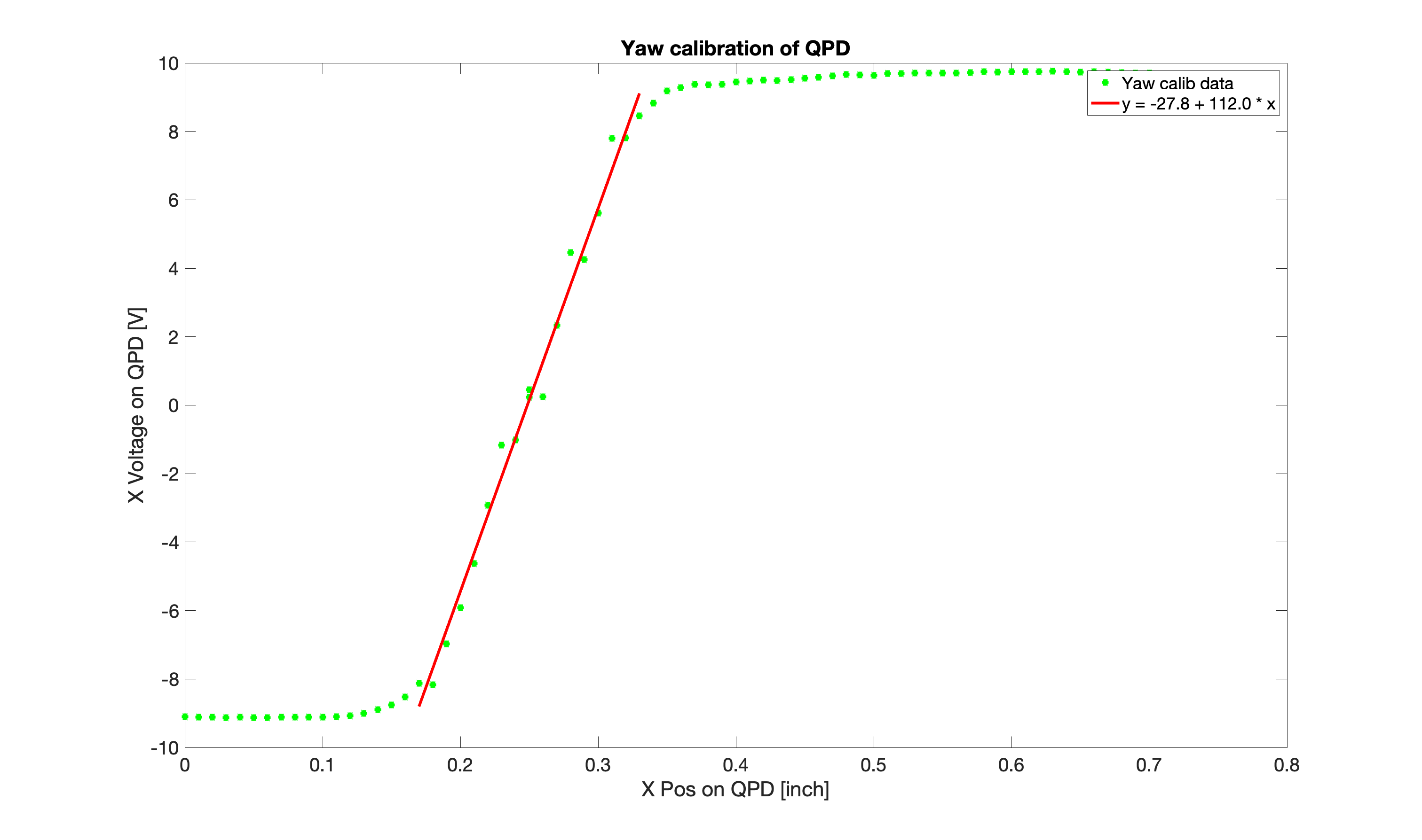
I plotted the data from lowest reading on the translation stage to highest and fitted the linear region using Calibrate_QPD.m which is attached.
Data is shown in attached pdf.
The slop of the linear region in V/inch is 112 V/inch. Which means to if the beam moved 8.93 e-3 inches on the QPD in yaw, the yaw readout would change by 1 Volt.

I altered the code to plot in mm and the constant is 4.4 V/mm.
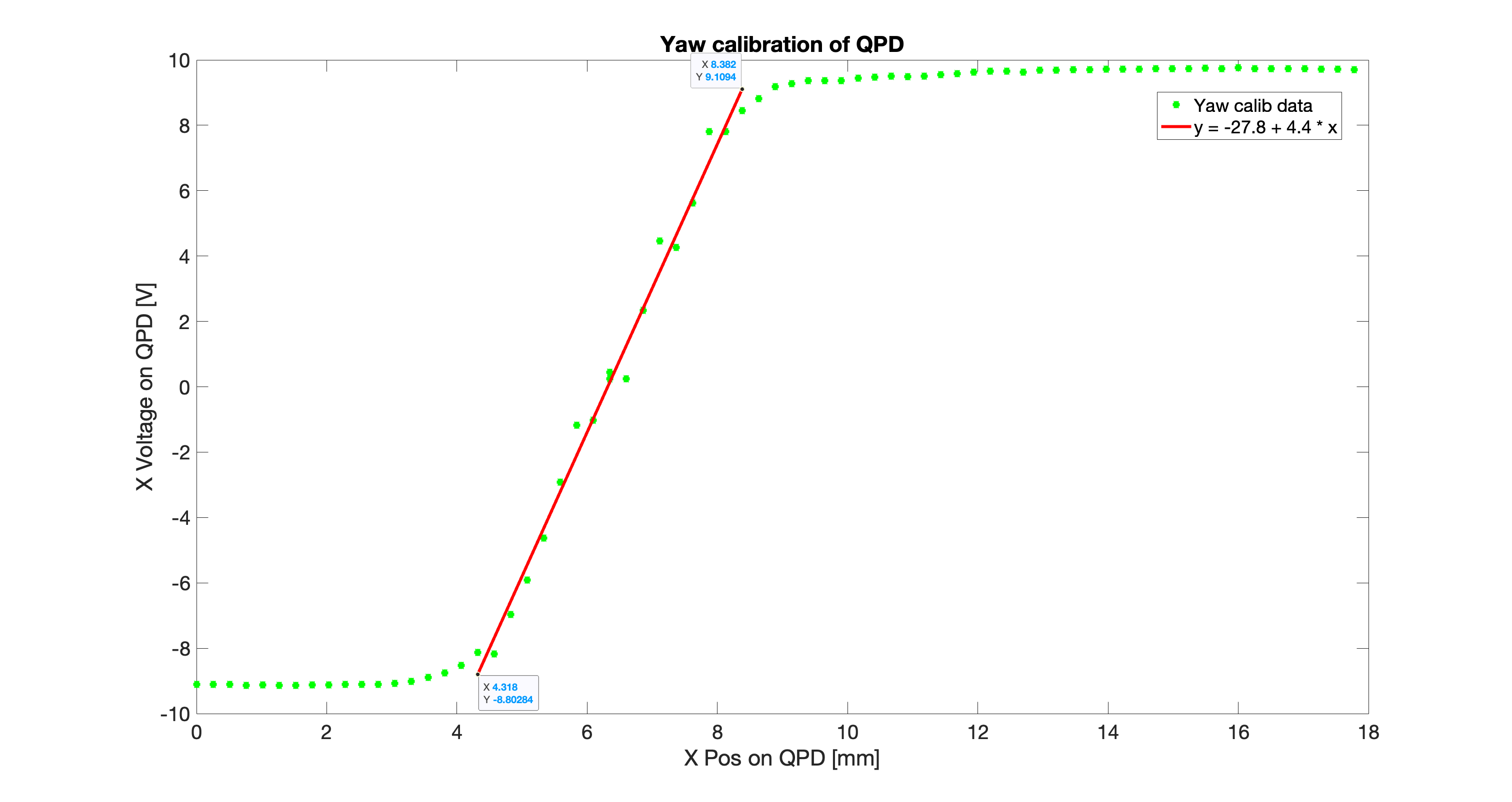
D'oh I read the scale on the translation stage wrong so the x readings are actually lower by a factor of 10.
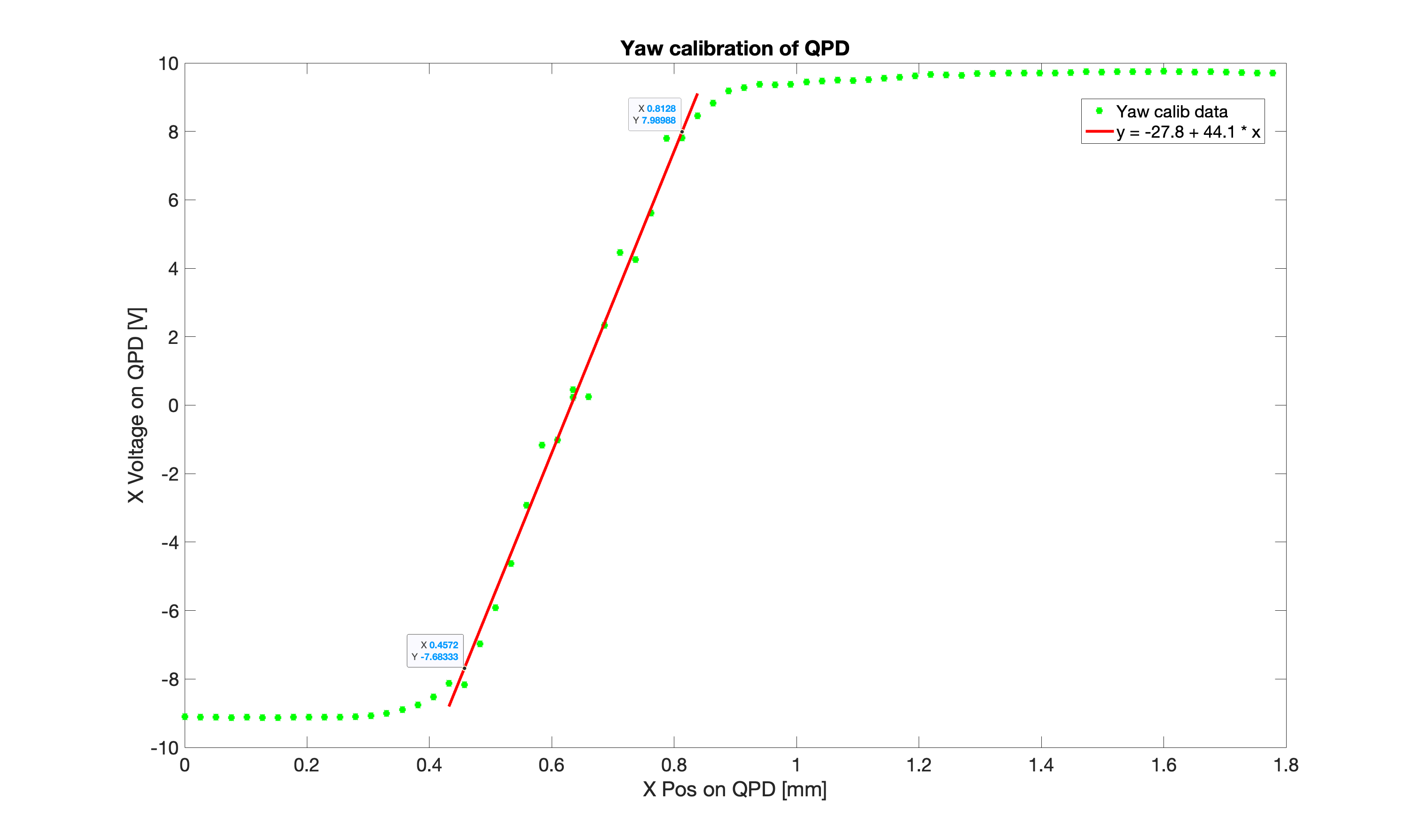
This makes the slope 44.1 V/mm which is more in line with the 65.11 V/mm Mayank and Shiva found for the QPD calibration here.
Ours could be different because we have a slightly different beam size and we moved the QPD in its housing to centre it which could have changed X to Y coupling in the QPD readout.
This implies our beam diameter on the QPD is around 0.4mm which makes a lot more sense considering the diode is 3mm!
As a cross-check we used the QPD 'bullseye' readout unit and Rahul changed the translation stage in yaw and we measured the beam dropping from 10400 counts in the middle of the QPP to 100s of counts at the edges.
| Translation Stage [inch] | QPD Sum Counts |
|---|---|
| 0.413 | 10400 |
| 0.365 | 500 |
| 0.413 | 10400 |
| 0.49 | 400 |
diode size ~ ((0.49-0.365)*0.0254*1000) = 3.175 mm.
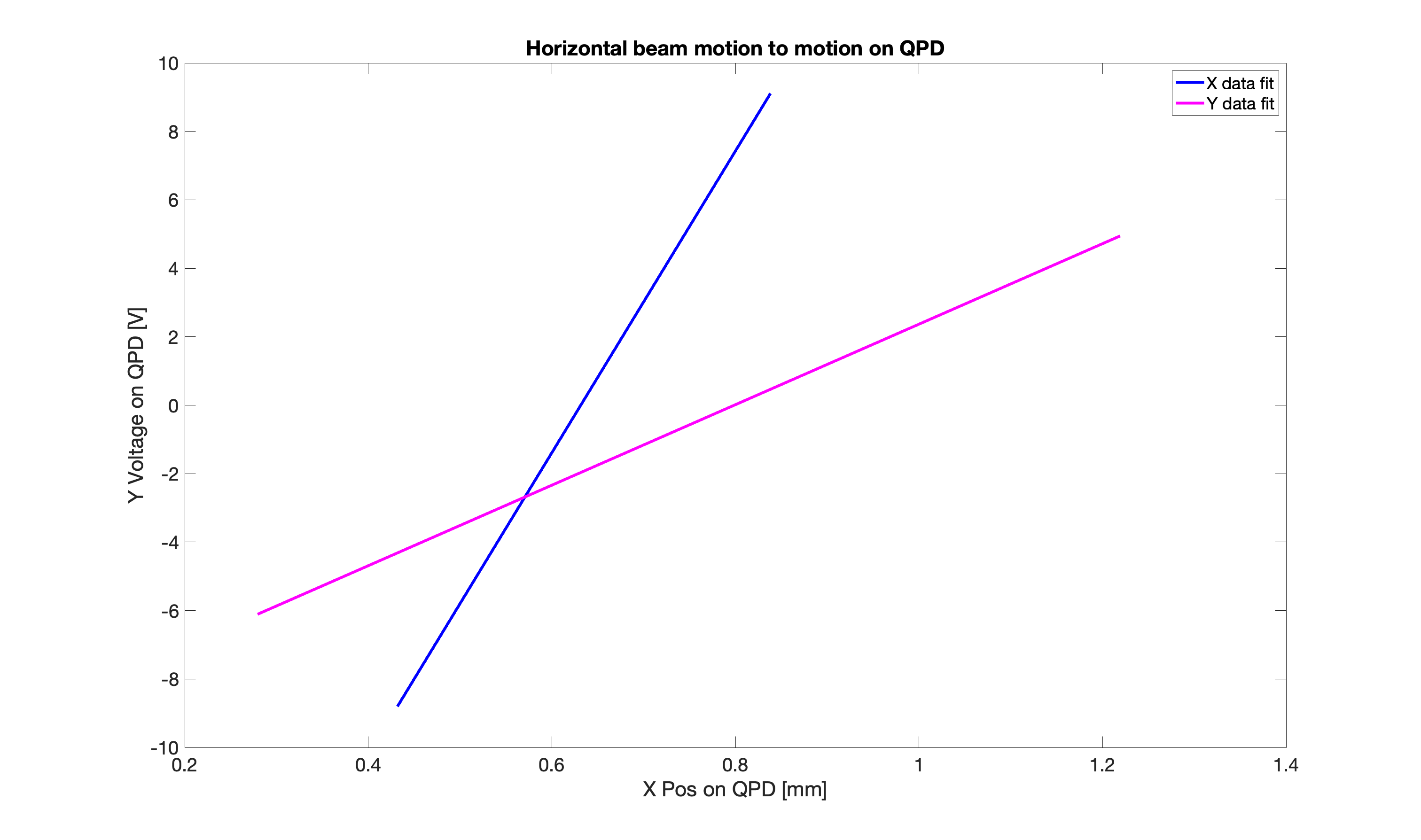
I redid the graphs for the horizontal motion of the input beam to X motion on the QPD with better labels (first attached graph) and did a fit for the Y data on the QPD collected at each horizontal position of the input beam (second attached graph). The third graph attached is comparing both fits on one graph.
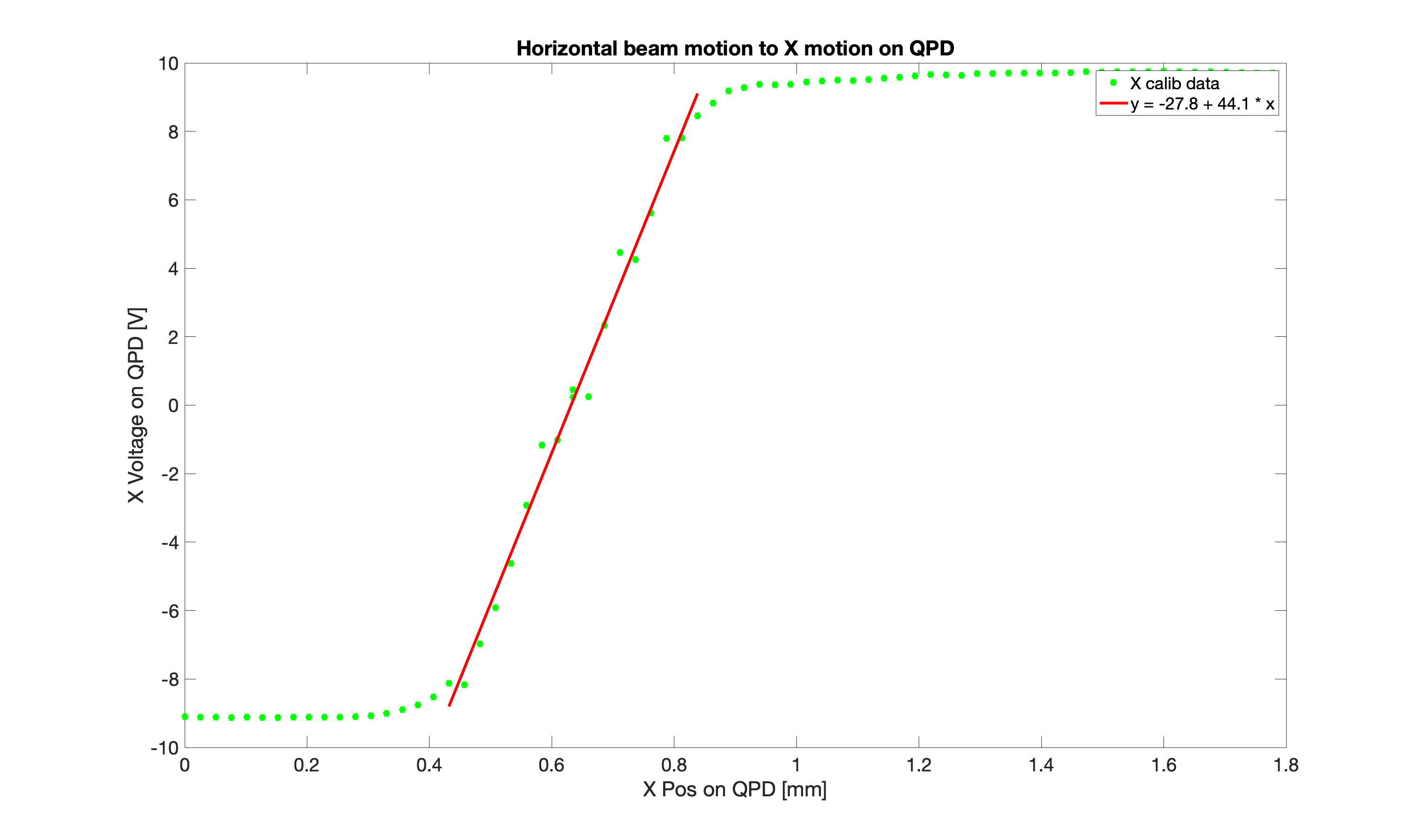
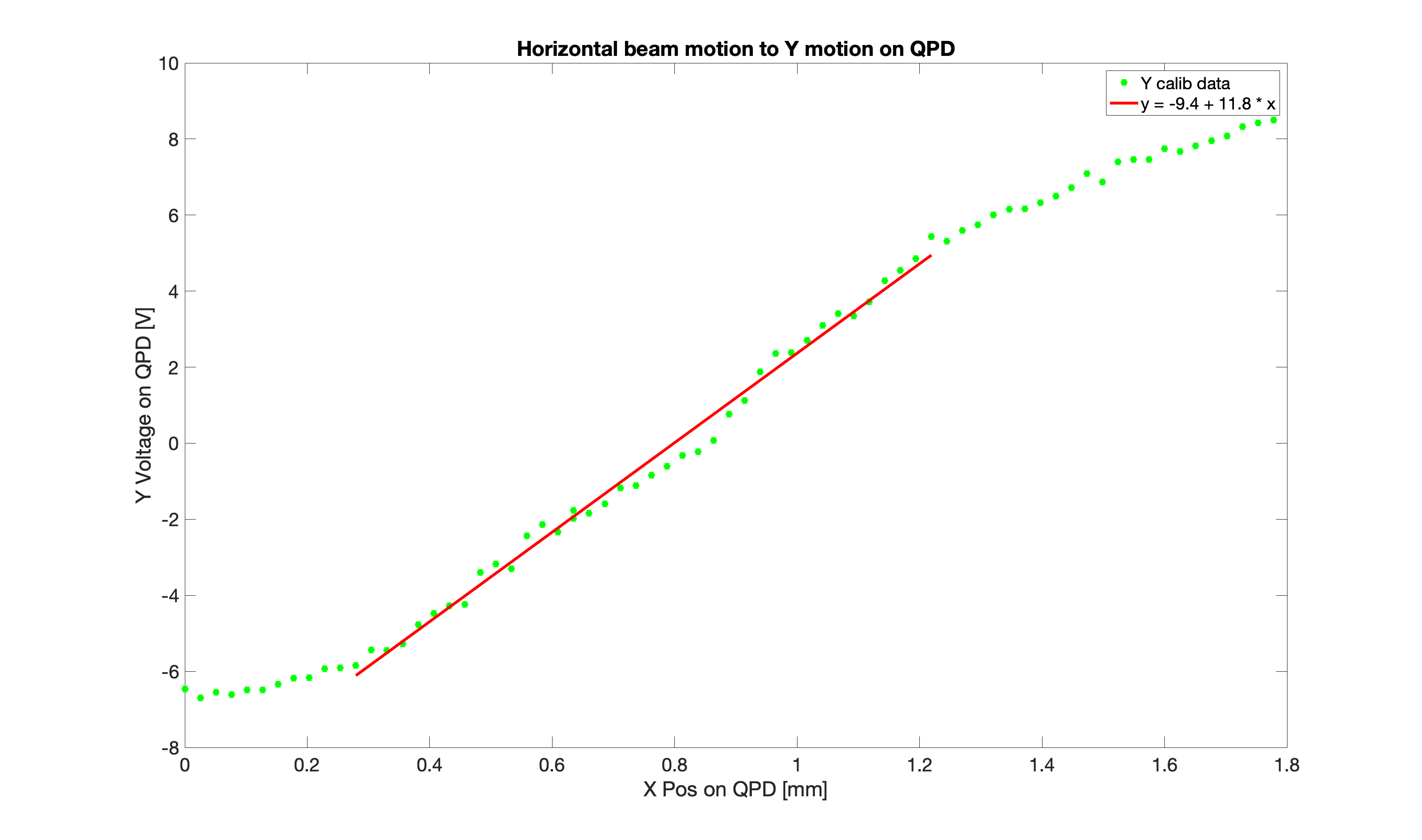
If we take into account the input beam horizontal axis is not aligned with the QPD, we can work out the resultant calibration relative to the mirror displacement as:
V change along mirror displacement axis = sqrt((change V in X)^2 + (change V in Y)^2)
Calibration = V change along mirror displacemnt axis/change in mirror position
= 4.644 V/mm.
angle of QPD horizontal axis with mirror displacement axis = tan^-1(Voltage change V in Y/ Voltage change in X) = 38.8 degrees.
I got the above caluclation of the QPD calibration in the horizontal direction wrong as I use the total change in voltage we measured across the whole range of horizontal scan and not just the linear region where the beam is close to centred on the QPD.
The horizontal beam scan calibration is actually:
sqrt(11.8^2 + 44.1^2) = 10.6 V/mm
with an angle of tan^-1(11.8/44.1) = 14.9 degrees to the X direction on the QPD.