Jennie W
Francisco is helping me read data from the oscilloscopes we are using for the PD readout so we can measure a QPD to PD transfer function to figure out how the PDs are mis-aligned.
While he was working on this I went to re-align the input beam to the array as our last measurements of the coupling amplitude in the horizontal direction showed that the coupling was much larger than Shiva and Mayank had previously measured.
I found we could get better coupling with the input beam off in yaw on the QPD - I got this by moving the closest steering mirror to the input aperture in pitch and yaw (as these are both coupled slightly due to the QPD y and x axis not being perfectly aligned with the steering mirrors pitch and yaw directions).
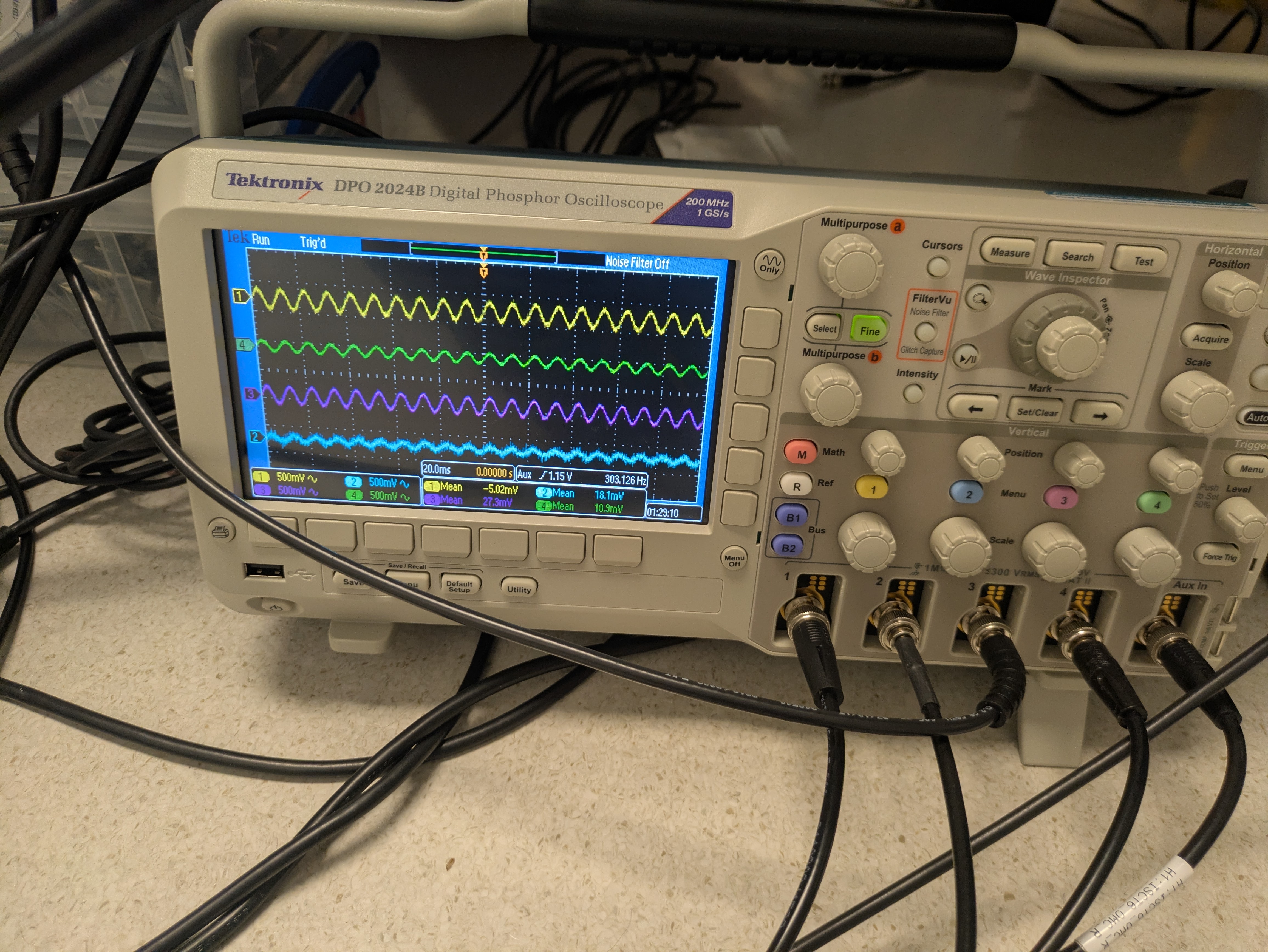
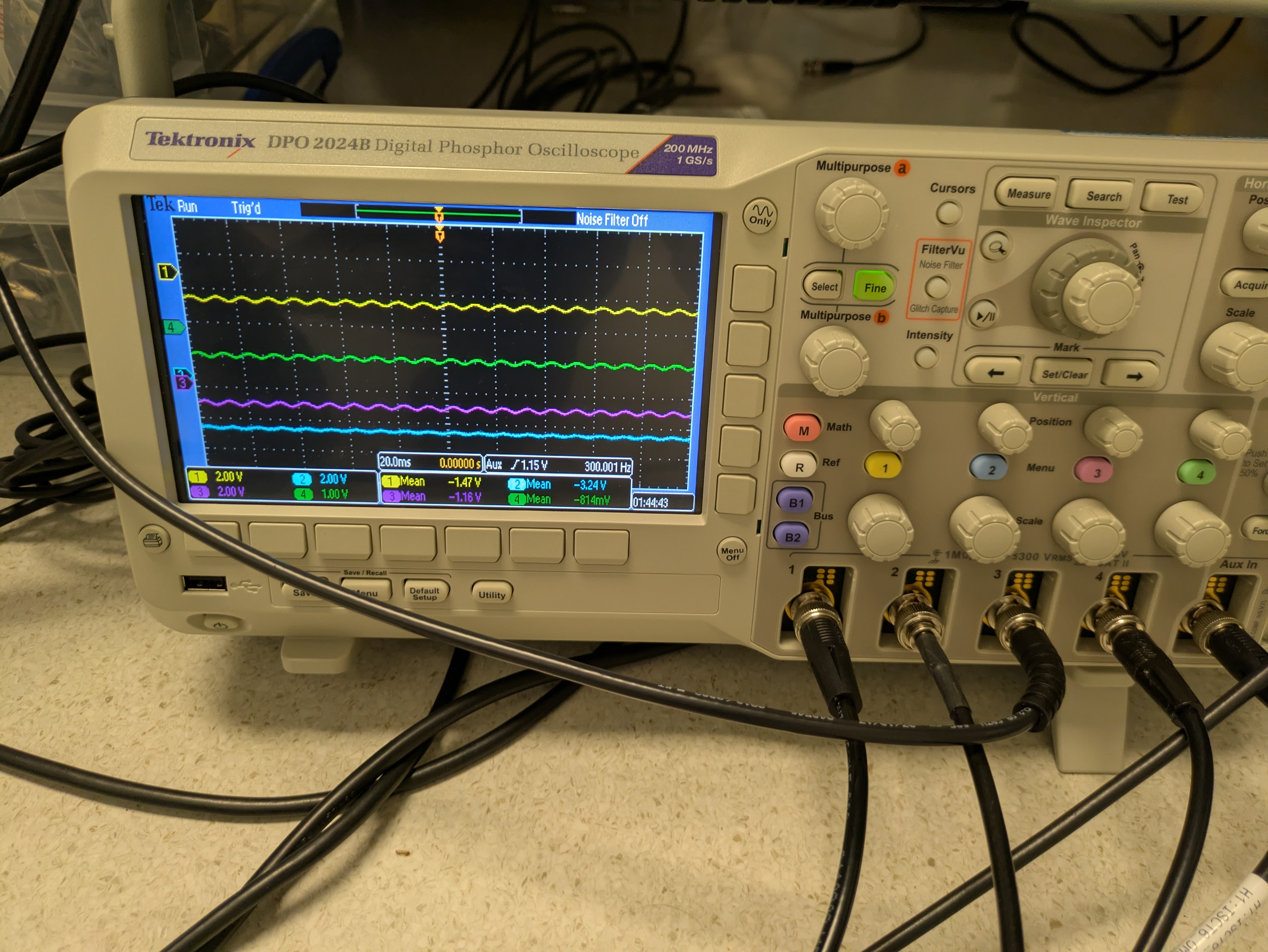
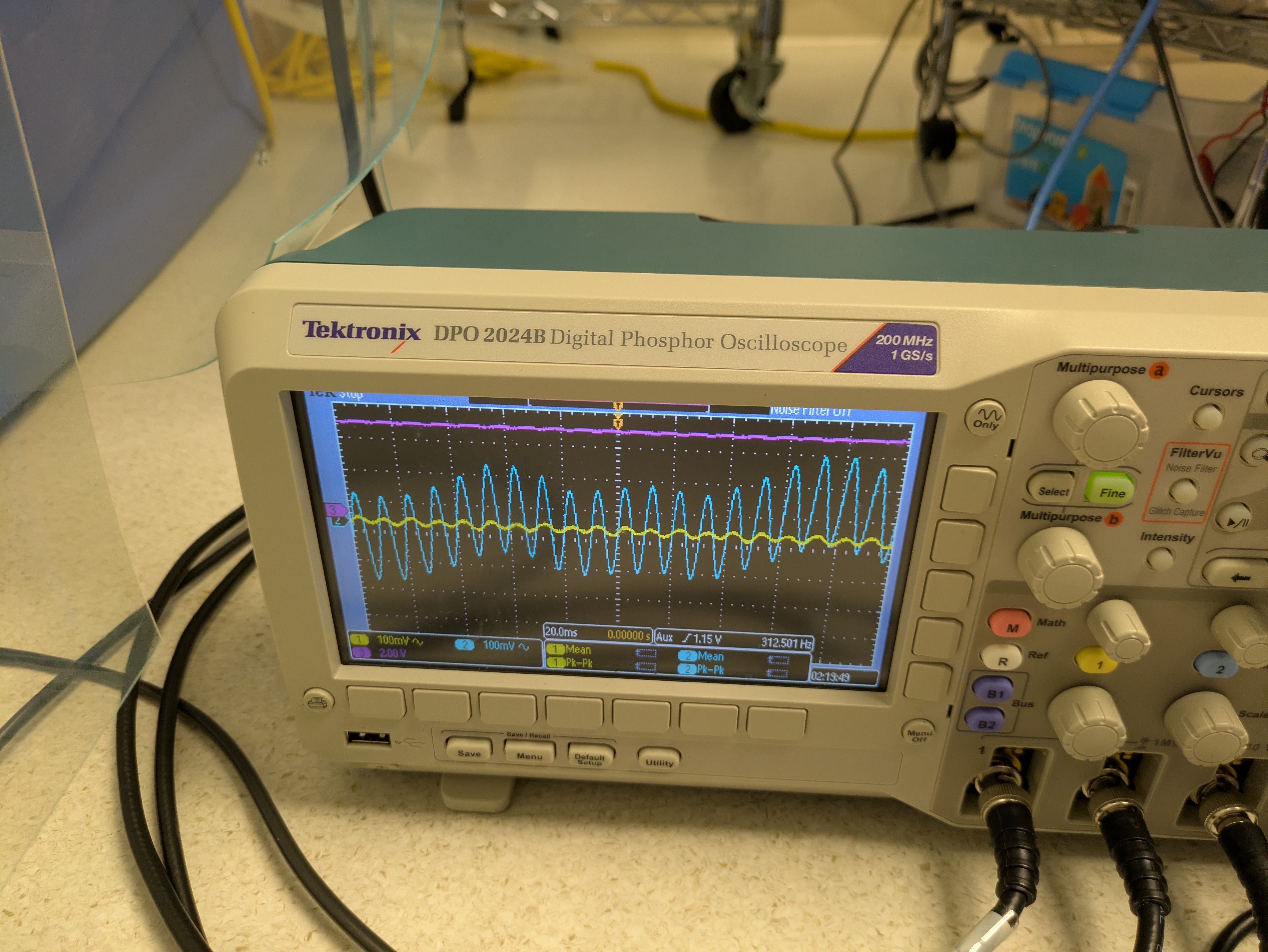
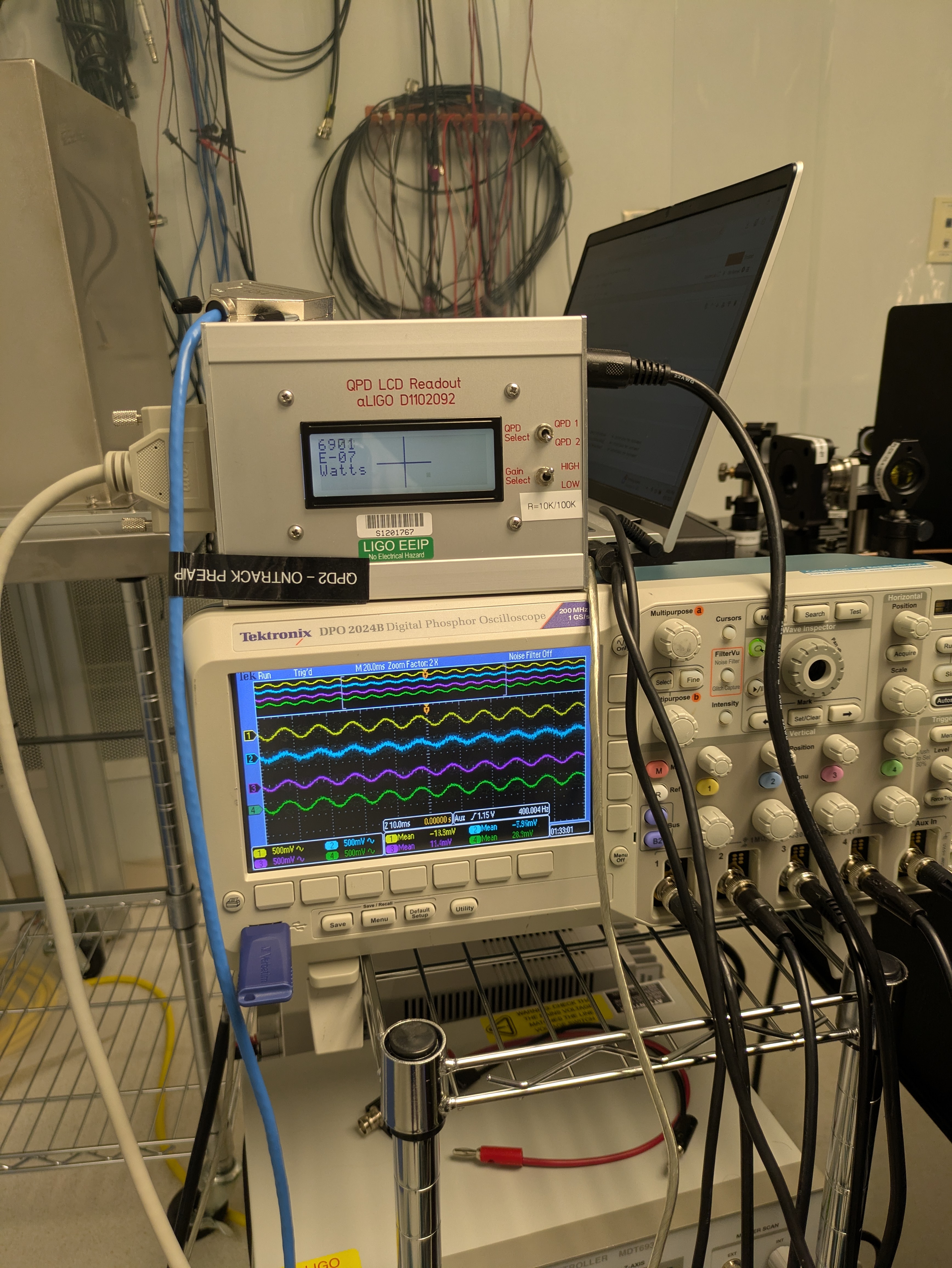
Pictures I took are attached, photos one (showing AC voltage of PDs 1-4) and two (AC voltage of PDs 5-8) are only moving the steering mirror in yaw but the light went off the centre of the QPD too much (we expect it to be above 10000 counts but here it is ~6000), so I found another spot with less power drop on the QPD that still has pretty good alignment coupling to the PDs. For this latter spot I also included the photo of the QPD readout.
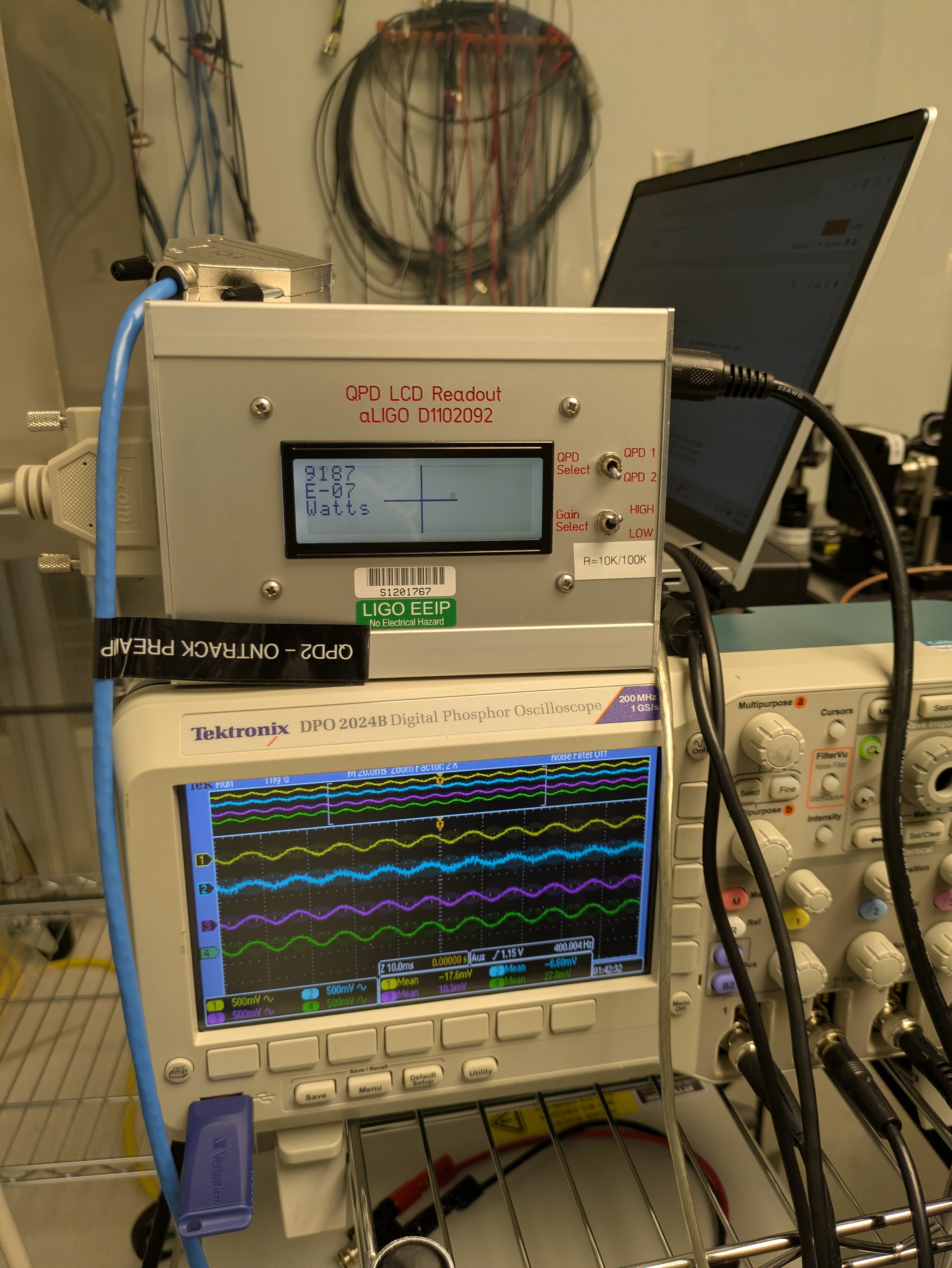
Photo 3 shows the QPD readout and the oscilloscope with the AC voltage values of PDs 1-4. The power on the QPD is about 9000 counts.
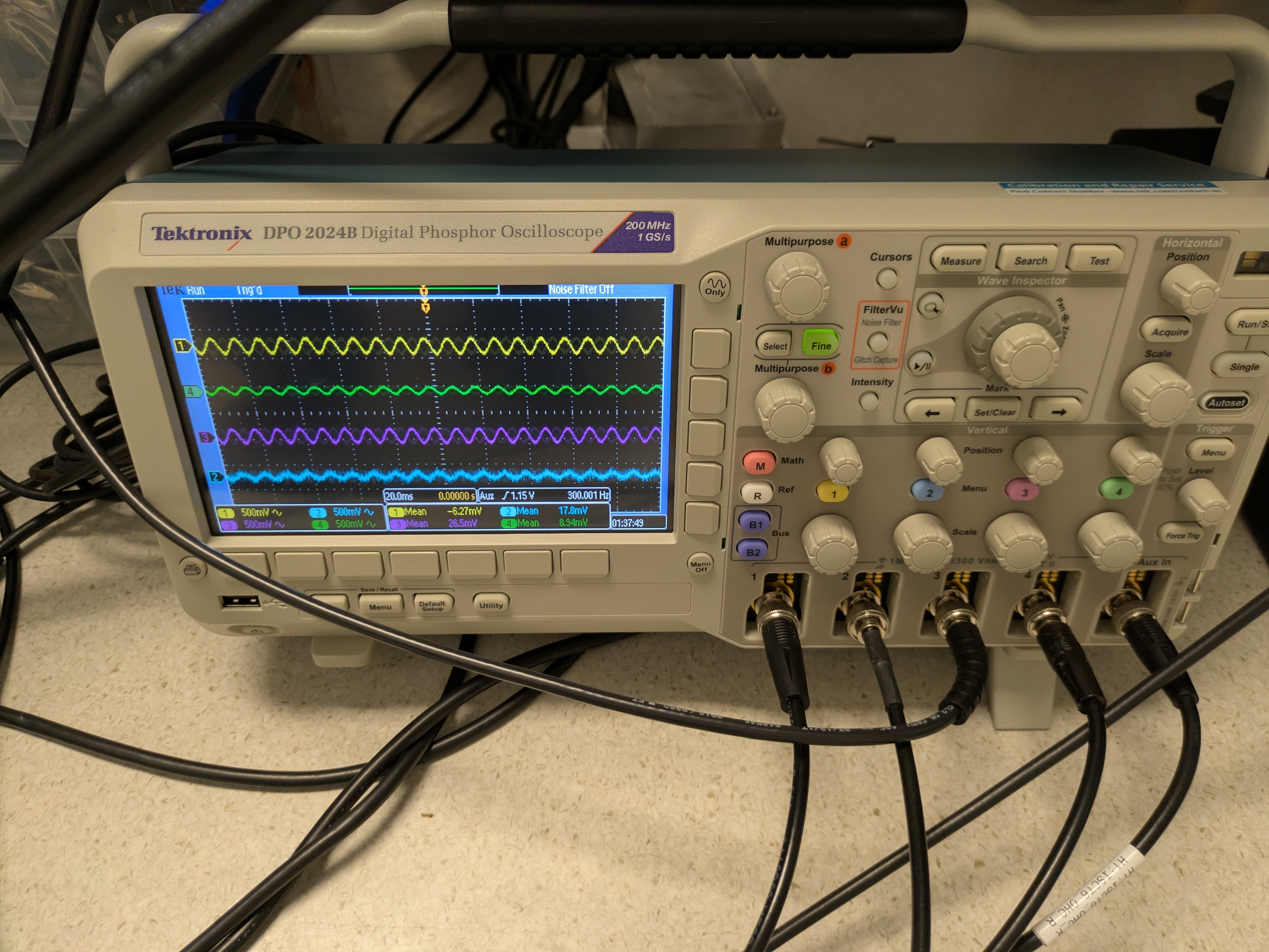
Photo 4 shows the oscilloscope with the AC voltage values for PDs 5-8.
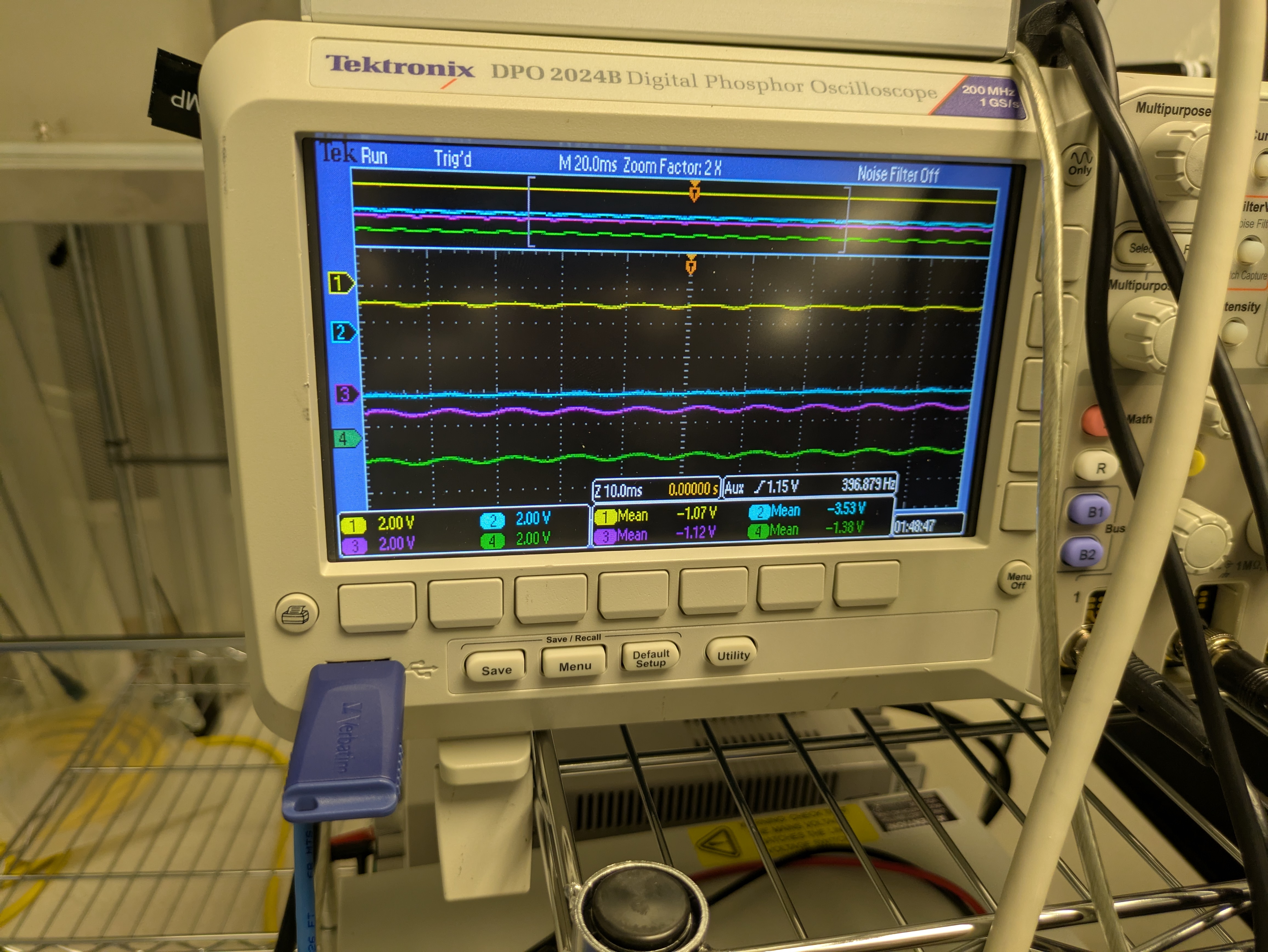
Photo 5 shows the oscilloscope with the DC voltage values for PDs 1-4.
Photo 6 shows the oscilloscope with the DC voltage values for PDs 5-8.
Photo 7 shows the x, y and sum channels for the QPD on an oscilloscope.
We might have to move the QPD in yaw to centre it for this pointing into the PD array.