jeffrey.kissel@LIGO.ORG - posted 20:29, Monday 11 August 2025 (86311)
SPi Optomechanics: Picomotor Assembly Components
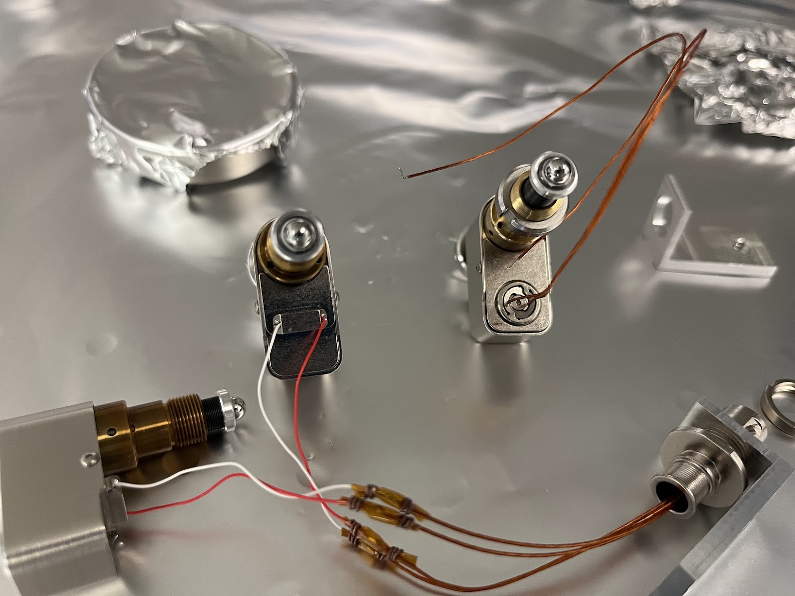
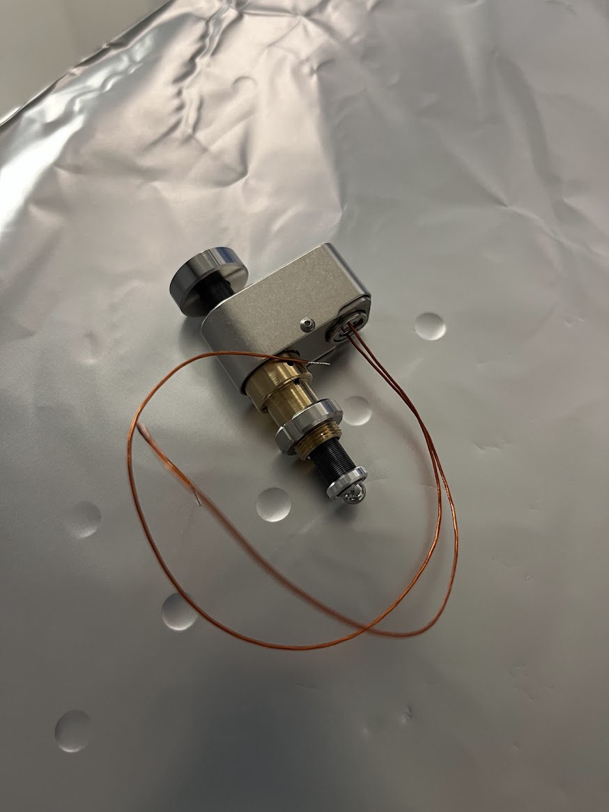
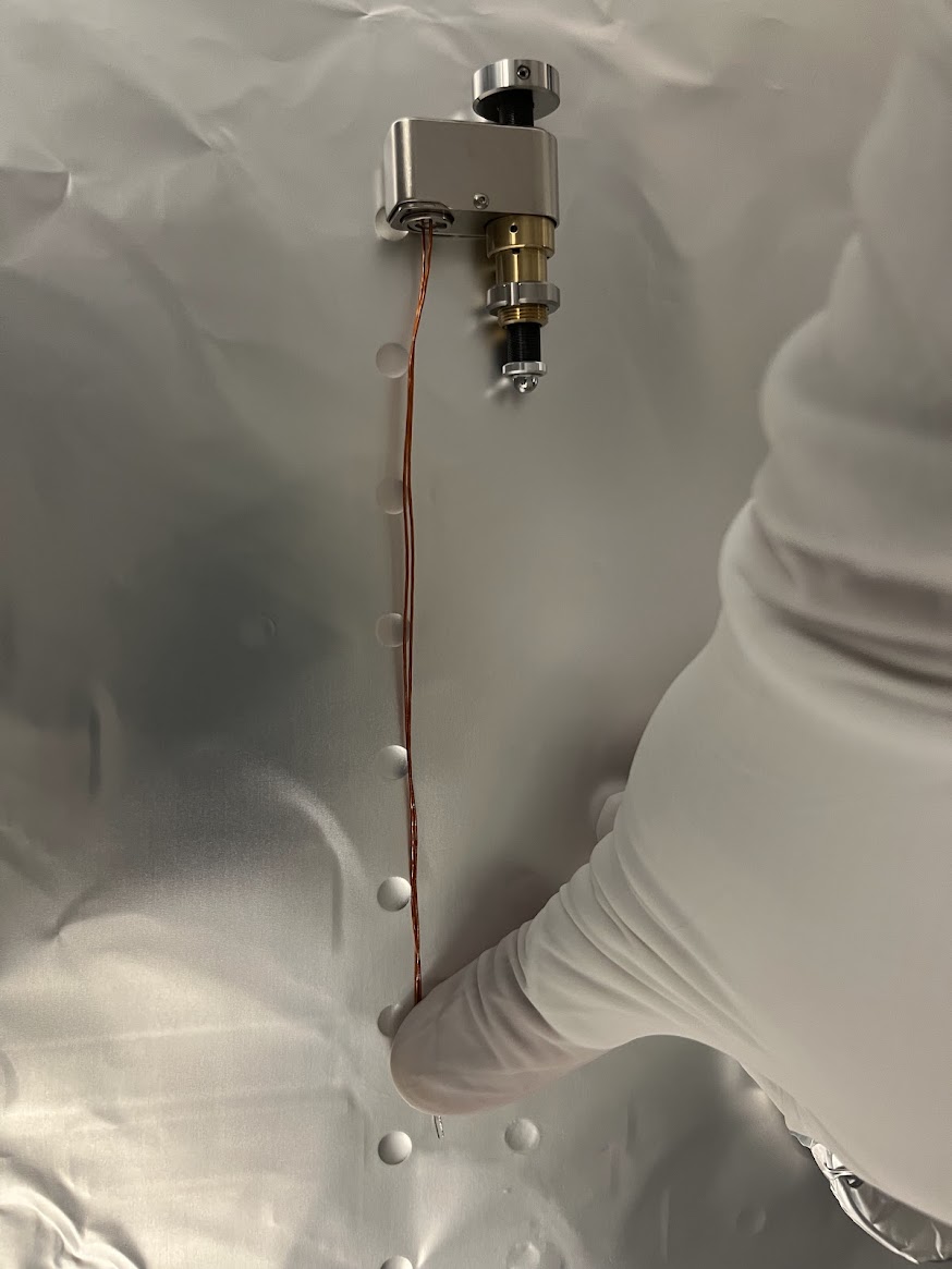
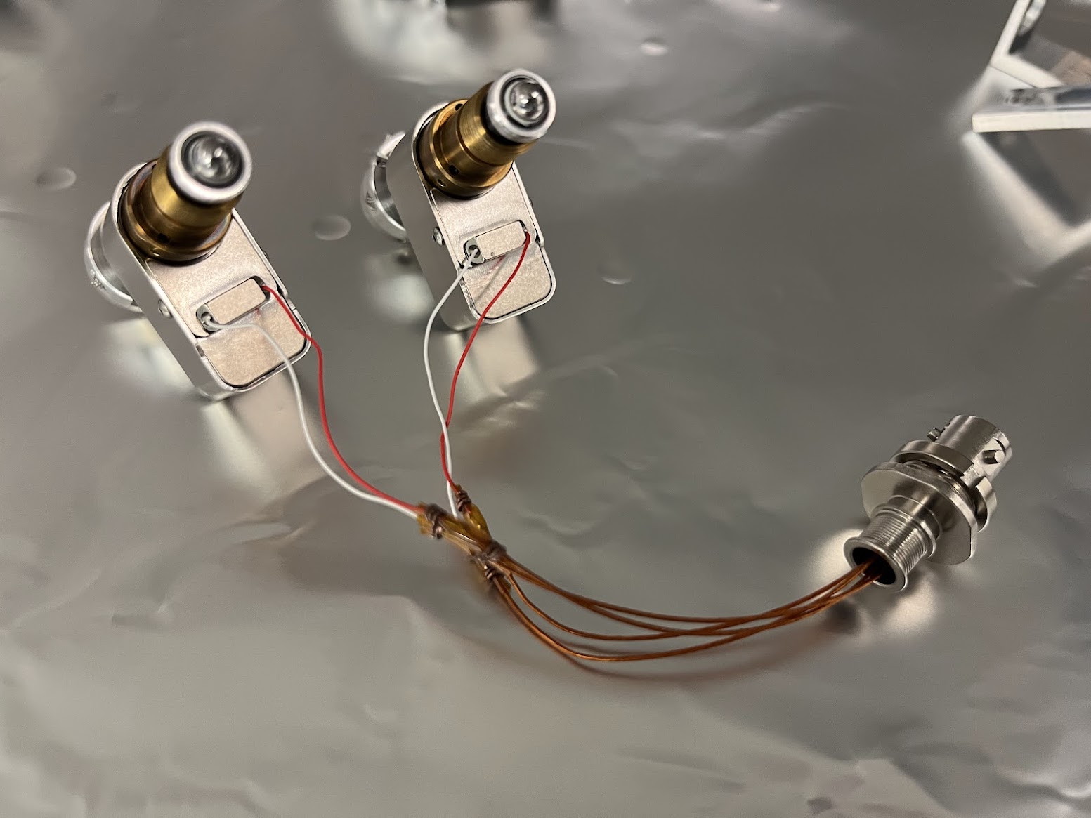
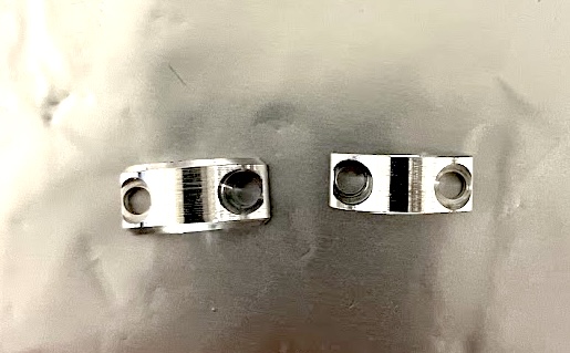
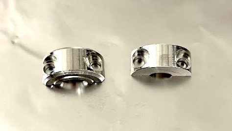
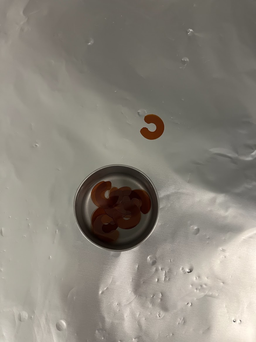
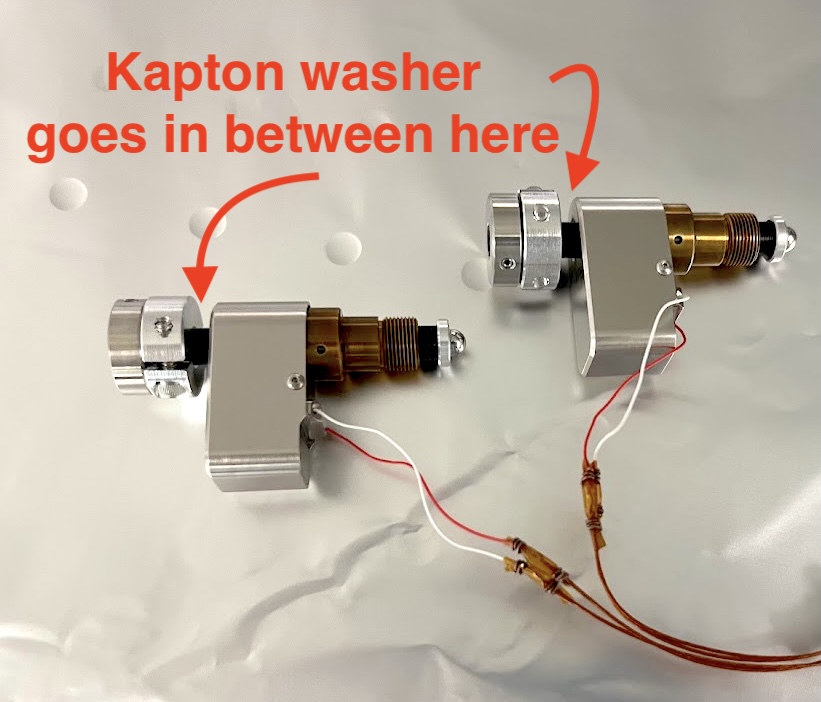
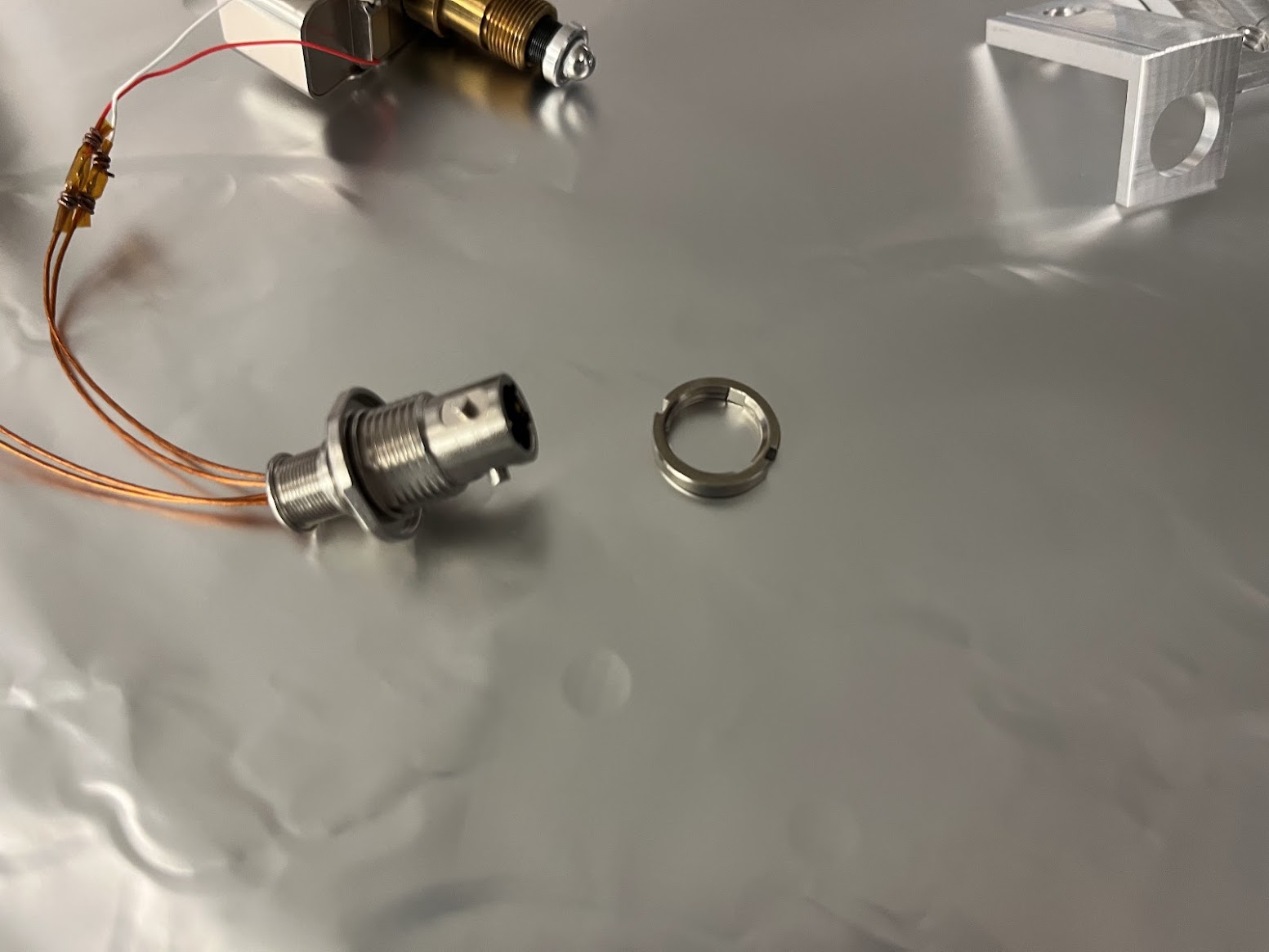
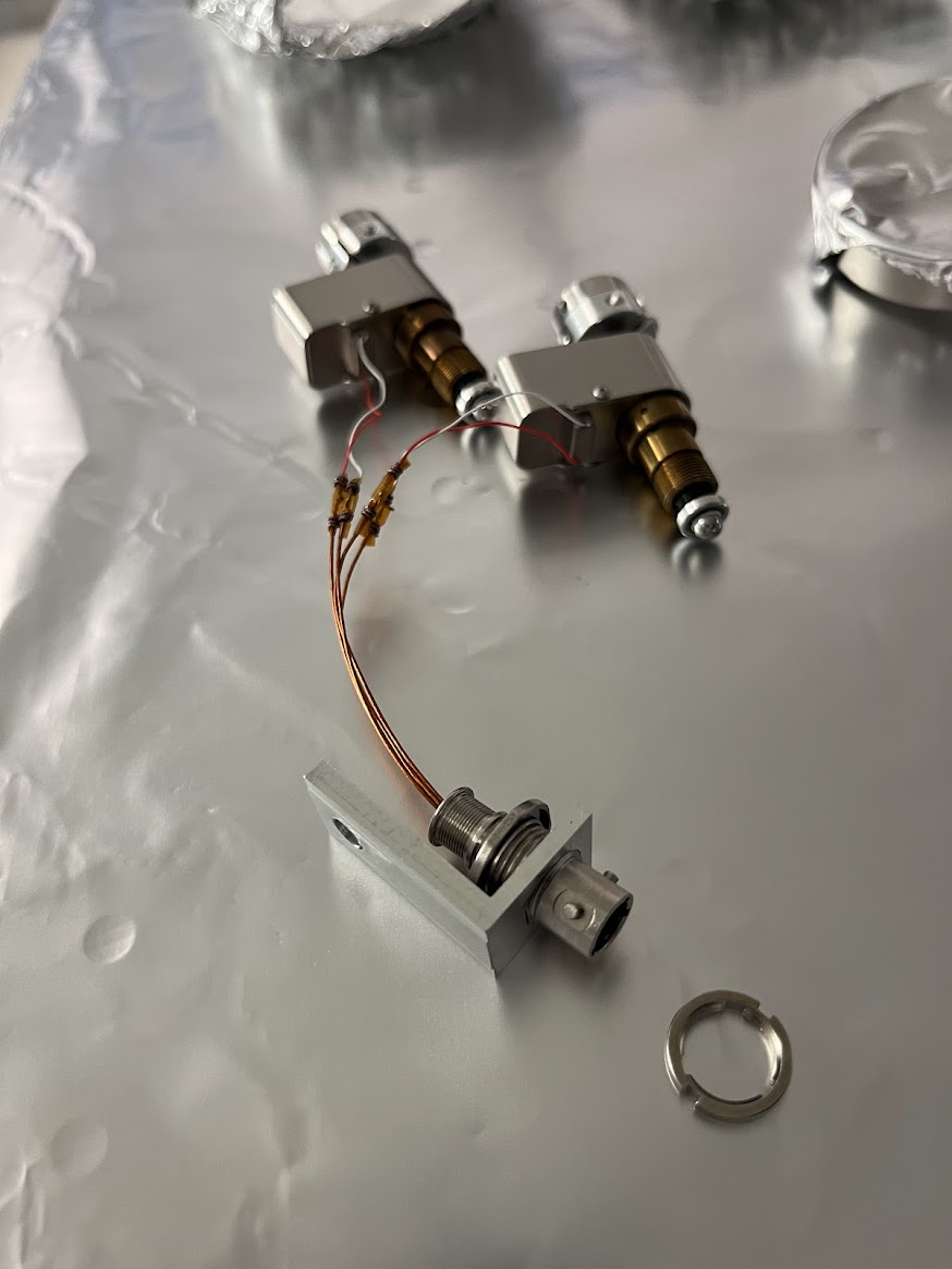
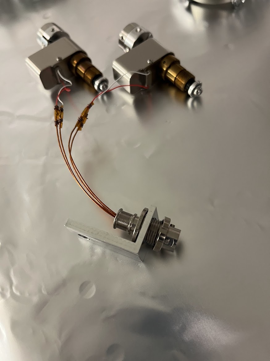
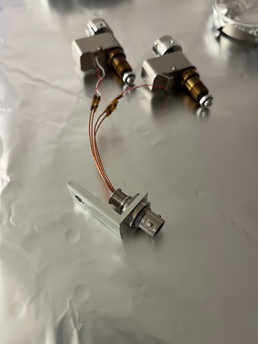
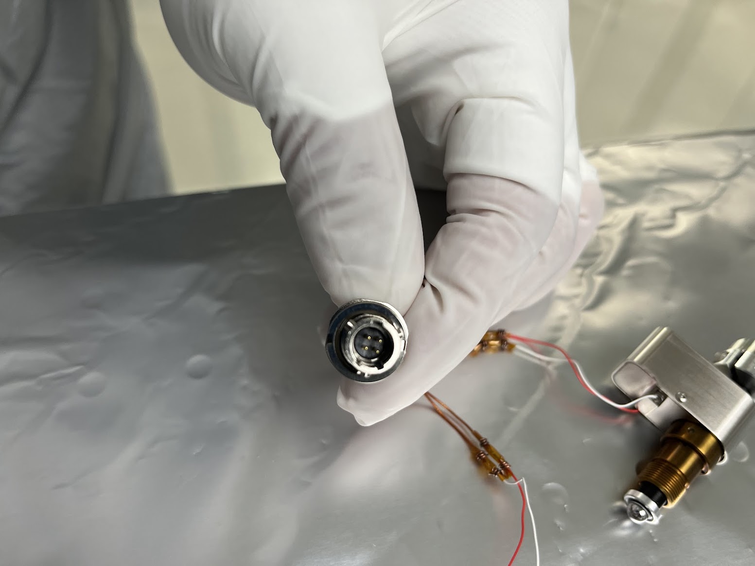
J. Kissel, C. Compton

Camilla and I took some pictures of what supply of picomotor assembly materials we (existing ICS Supply vs. what SPI) have and in what state of assembly they are in order to familiarize myself with the process of building up new assemblies.

To the best of my knowledge, there's no assembly procedure. Instead, we have the Picomotor Fact Page (E2100196) [which I've, as of this aLOG, heavily updated / curated]:
    - A well-labeled exploded assembly drawing with only minor assembly errors, (Page 2 of D2100433)
    - a hand illustration from Rich on the wiring connections for an IXM100.C2, right-handed mount (D1400279)
    - the expected two-motor pinout of the receiving D25M to 4x MM4F quadrapus cable (D1101516)
    - Some instruction on how dis-mount and re-mount fully assembled picomotors (E2500163)
and thru a linear combination of these, you could fumble your way through it.

The picomotors themselves have evolved over the years as the original prefer vendor, New Focus, was bought out by Newport.
:: First picture shows the difference between an old picomotor (left), and the modern 8301-UHV-KAP that we buy now (right). I've created D2500246 (as opposed to the old, non-specific E1000197) that captures the specific features of this model. The key differences between old vs. new being
    - The wires' insulation is kapton, not colored teflon
    - The wire lengths is a nice healthy 7 [in], not a short 2 [in] that required icky extension
    - The label of which wire is which is stamped into the metal (a "-" in the lower-left corner to indicate that the wire closest to that stamp is the negative lead, or "return") vs. indicated by color of wire.

:: Second picture shows the modern 8301-UHV-KAP picomotor by itself. Note, the "1" in 8301 indicates that we've chosen the 0.5" throw.

:: Third picture shows the cable unfurled and compared against the 1 [in] hole pattern of the optical table beneath the foil.

OK, now that you've gotten to know the raw picomotor, let's talk about cnonnectorizing and modifying it to suit our needs. We only have the old style picomotor fully assembled to picture as example, but it'll serve the purpose.

:: Fourth picture shows the real manifestation of Rich's artist impression of the fully connectorized two-motor system.

:: ECR E1400327 has us install a motion limiting shaft collar along the throw of the picomotor to limit the motion from the edge of its range where it's been found to get stuck. The collar was originally a custom D1400189 per -v1 of the ECR, but now it's a stock McMaster Carr shaft collar (6436k131, with the black-oxide steel #4-40 x 3/8 [in] L SHCS replaced with a stainless, otherwise identical, SHCS, 92196A108). The stock collar is then modified to be a bit thinner, per D1800220. Finally, to prevent the shaft collar from freezing against the picomotor body, we install a slip-on LIGO-cut kapton "washer" (D1400226; cut from 12 [in] x 12 [in] x 0.005 [in] sheet stock) around the threaded adjustment screw.
    - Fifth and Sixth pictures show how the shaft collar is shaved thinner,
    - Seventh picture shows the Kapton washers,
    - Eighth picture shows the collars assembled on the motor, and where the washer would be placed (these didn't have washers at the time of the picture, but we've since installed the on their to form a complete, albiet not-so-vacuum-compatible assembly).

:: Once connectorized, per Rich's drawing, to the 4-pin MMF connnector 803-003-07M6-4PN-598A, then the connector is secured to a custom L-bracket D1002763 via the connector's thumb screw. That L-bracket then secures to the optic mount's "other" 1/4"-20 mounting hole (with "the" 1/4"-20 mounting hole, 90-deg away, is presumably used to secure the mount to a post or breadboard). Note -- the L-bracket's thru-hole for the MM connector is keyed, but it's not sized for any feature on the actual connector, so you're free to orient the connector in any way in within the bracket. Of course, each socket connector on the legs of the quadrapus it'll connect to are much better keyed, so there's no worry of pin-clocking or anything nasty like that.
    - Ninth picture shows the D1002763 L-bracket. Note -- this a D1002763-v2 Type 1 bracket, so it's mounting hole is threaded for 1/4"-20 bolt (rather than Type 2 which has a thru-hole requiring a nut).
    - Tenth, Eleventh, Twelth, and Thirteenth pictures show how the MM connector is assembled on to that portion of the D1002763 L-bracket.

Finally, just because it came up during the pre-clean-and-bake inspection (see discussion in CNB:2225),
    - Fourtheenth picture shows the inside of the 803-003-07M6-4PN-598A MM connector -- a  black plastic that Glenair calls a "High Grade Rigid Dialectric," without specifying the material (see table in Section 3.1 on page 2 of Mighty_Mouse_Series 80_performance-test-report-iaw-mil-dtl-810.pdf from T2500025).
I mostly show the picture of the old connectorized picomotor system to indicate that we've indeed been using this connect and its inner material for a long time, and the Clean-and-bake process (T2100001) appears to be enough (see e.g. bake loads ICS:10543 and ICS:10557).
Images attached to this report