Camille Makarem (CIT), Rahul
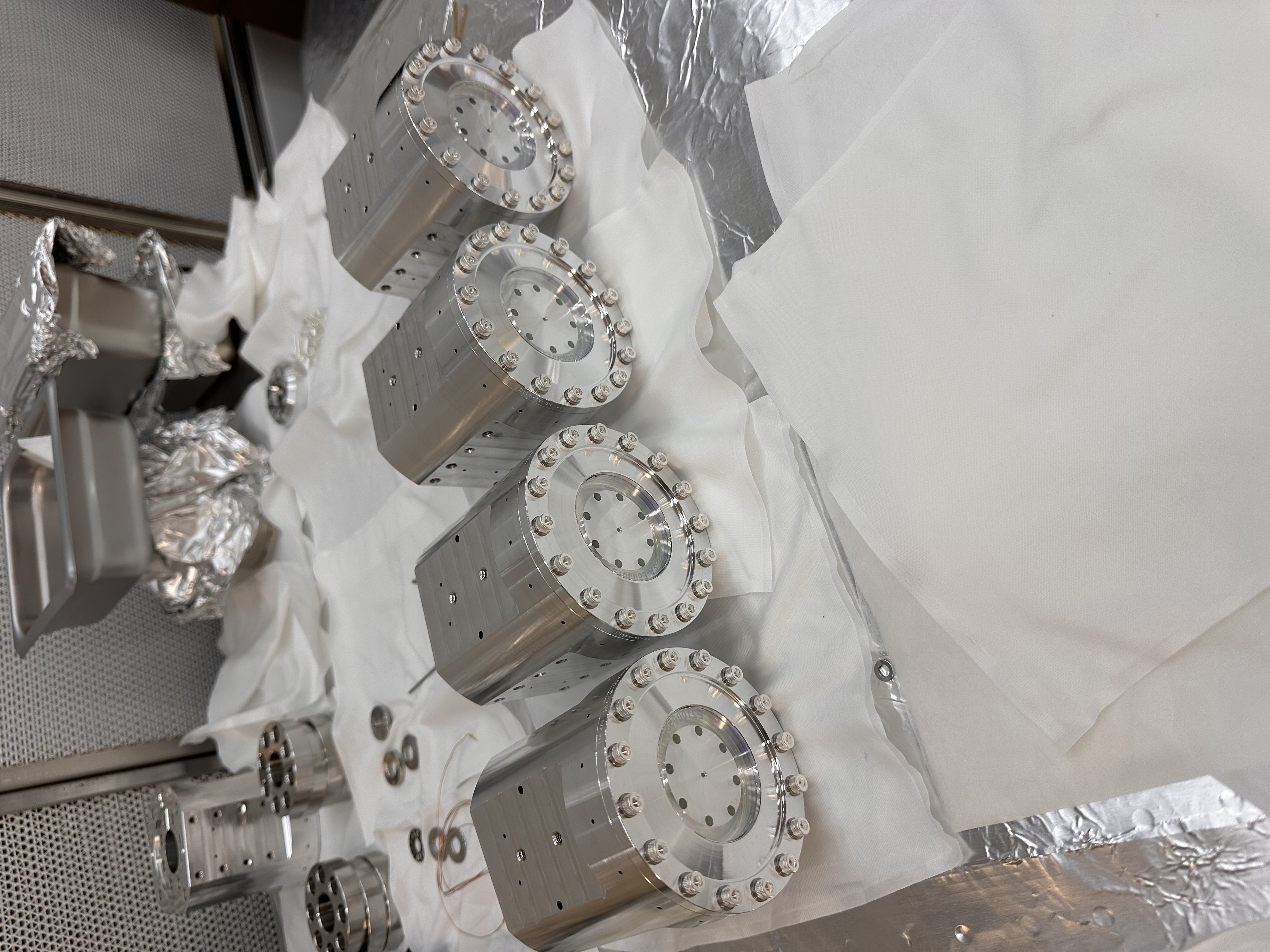
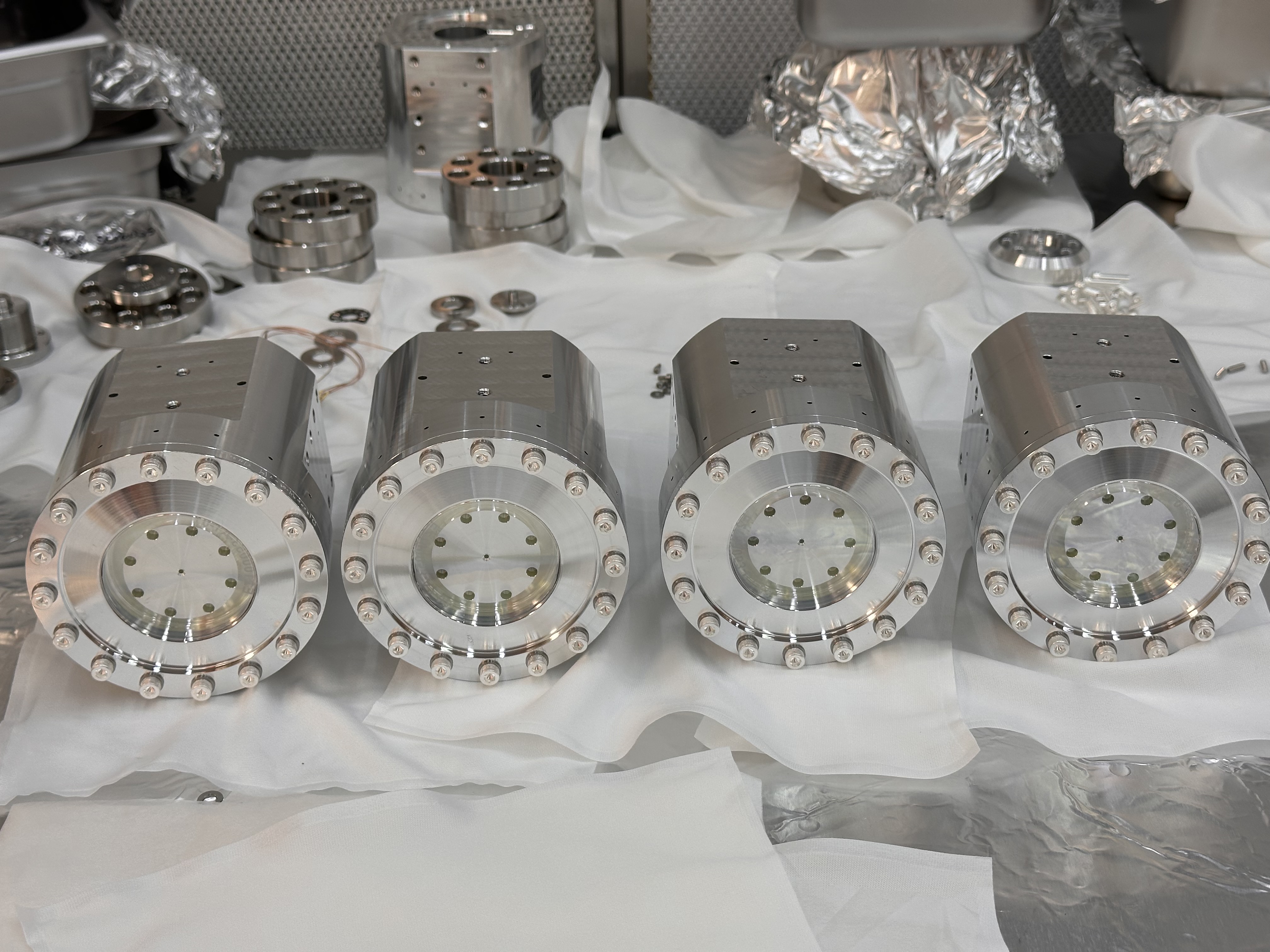
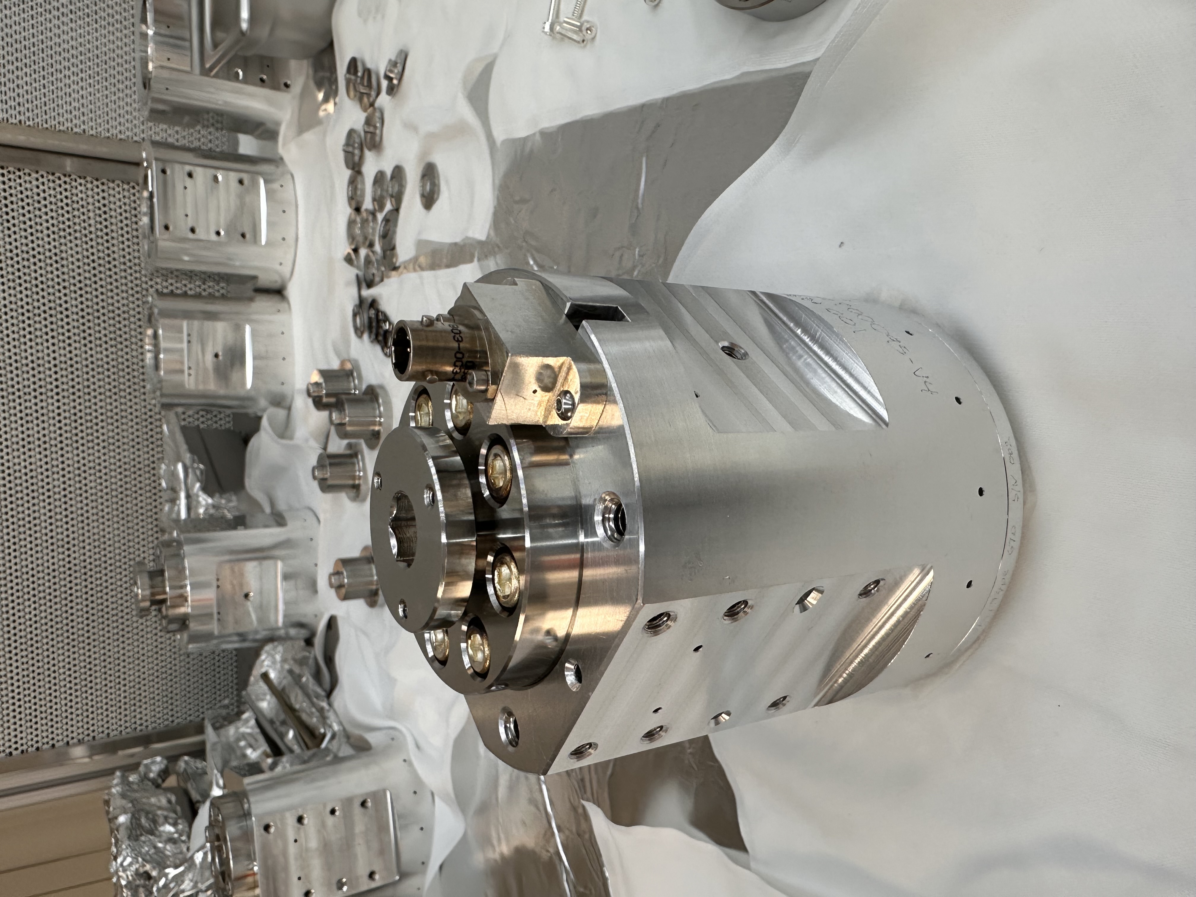
Last week at CIT we assembled and tested four units of PSAMS (Piezo-SAMS payload - Piezo-deformable Mirrors for Active Mode Matching). These four fully assembled PSAMS are shown in attachment01 and attachment02 and they will be shipped to LLO for O5 HPDS assembly and installation in HAM6. Given below are the test results of the PSAMS payload - PZT actuation and the desired radius of curvature of the mirror at 100V.
1. Optic E2100053, Type A2, s/n - 02 - PZT voltage tested from 0 to 200V, Pre-load set to 32 in. lbs at 100V DC, RoC = 2.42 m
2. Optic E2100053, Type A1, s/n - 01 - PZT voltage tested from 0 to 200V, Pre-load set to 32 in. lbs at 100V DC, RoC = 5.76 m
3. Optic E2100053, Type B2, s/n - 01 - PZT voltage tested from 0 to 200V, Pre-load set to 30 in. lbs at 100V DC, RoC = 2.41 m
4. Optic E2100053, Type B1, s/n - 03 - PZT voltage tested from 0 to 200V, Pre-load set to 28 in. lbs at 100V DC, RoC = 5.63 m
The Strain gauge readout results will be posted later on.
PSAMS assembly details and issues (faced) are discussed below,
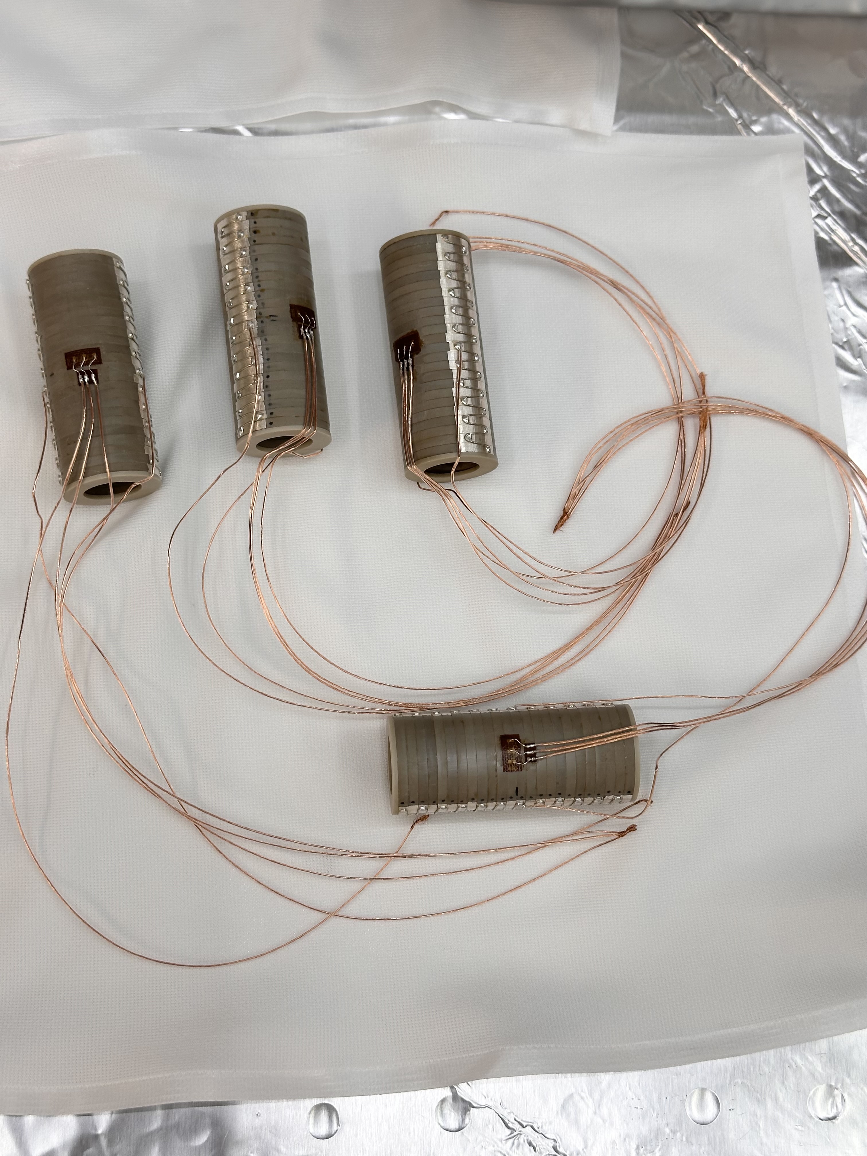
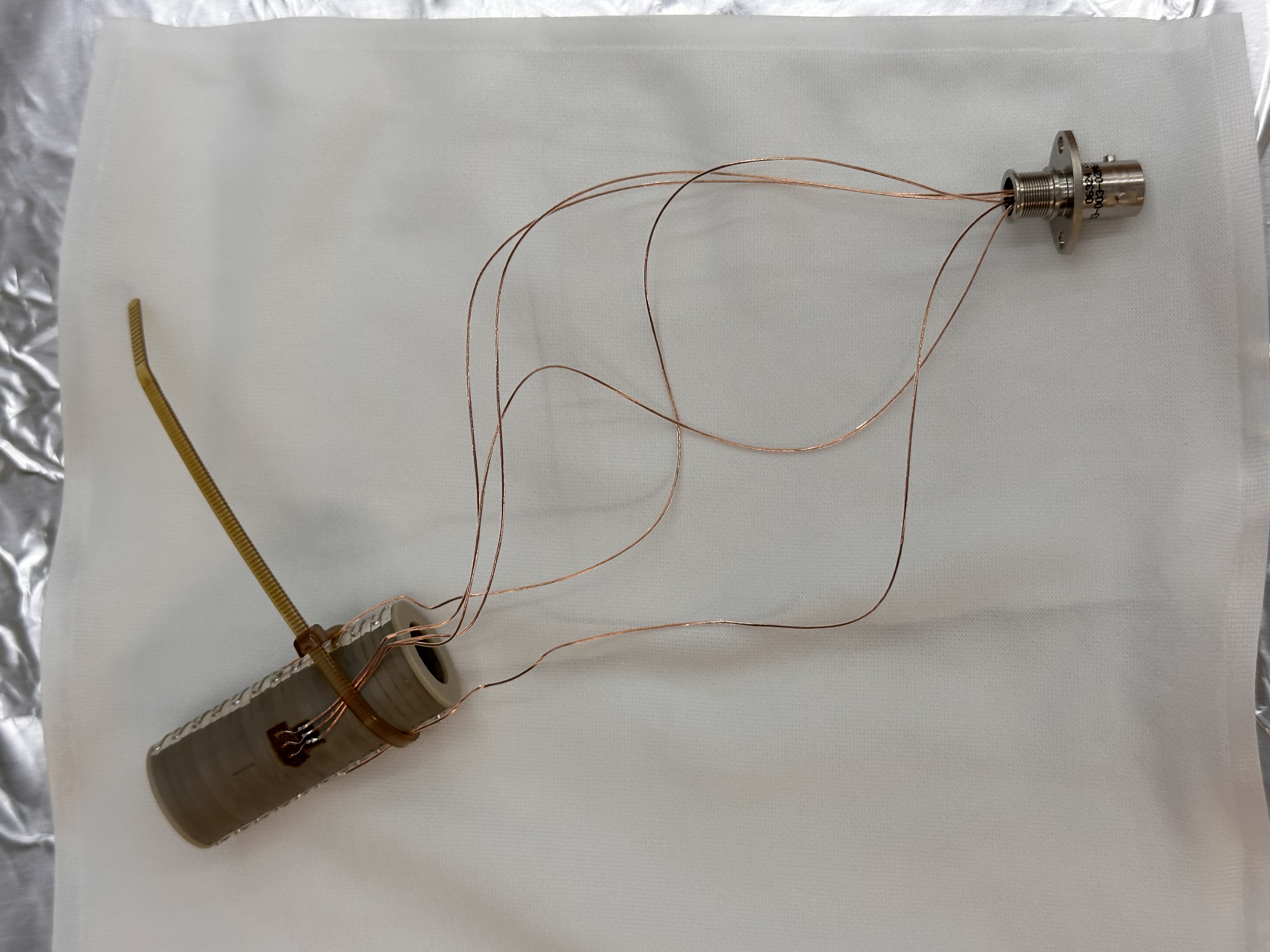
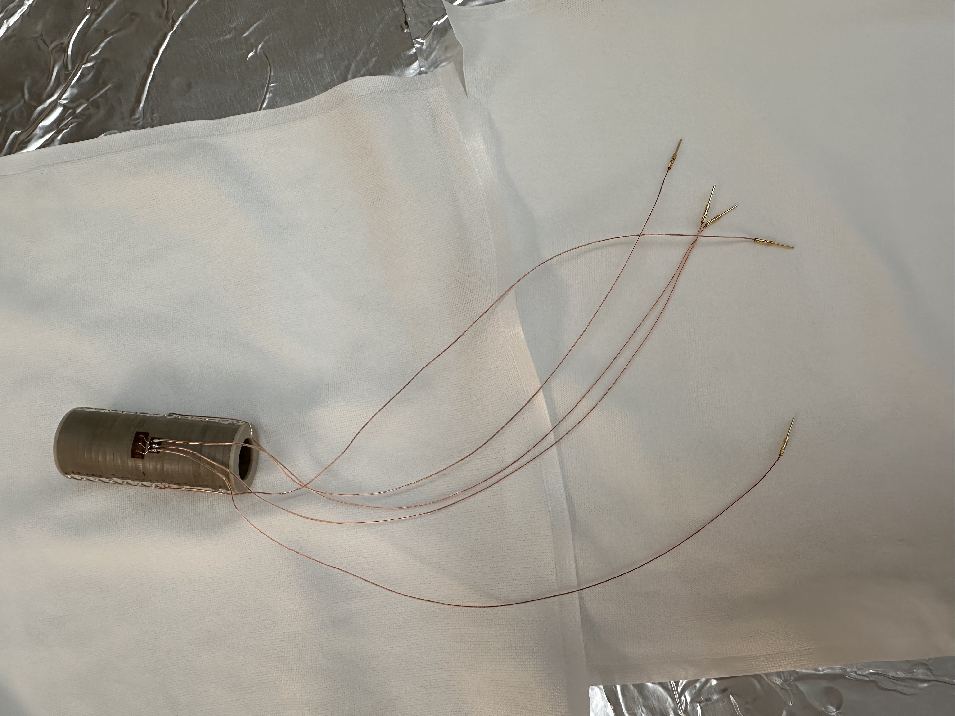
a. Attachment03 shows the PZT with five lead wires. We looked into the vendor data to identify + HV PZT (the side which has been marked with dots) and PZT ground (non dotted side). The other 3 leads belong to the Strain Gauge (SG). We crimped pins to all five leads - as shown in attachment04. The wire pins were then pushed into the 7 pin Glenair might mouse connector (MM 803-003-02M6-7PN-598A) - as shown in attachment05. We also used a PEEK zip tie to secure the wires on the PZT stack. We followed D2000383 for the wiring chain diagram.
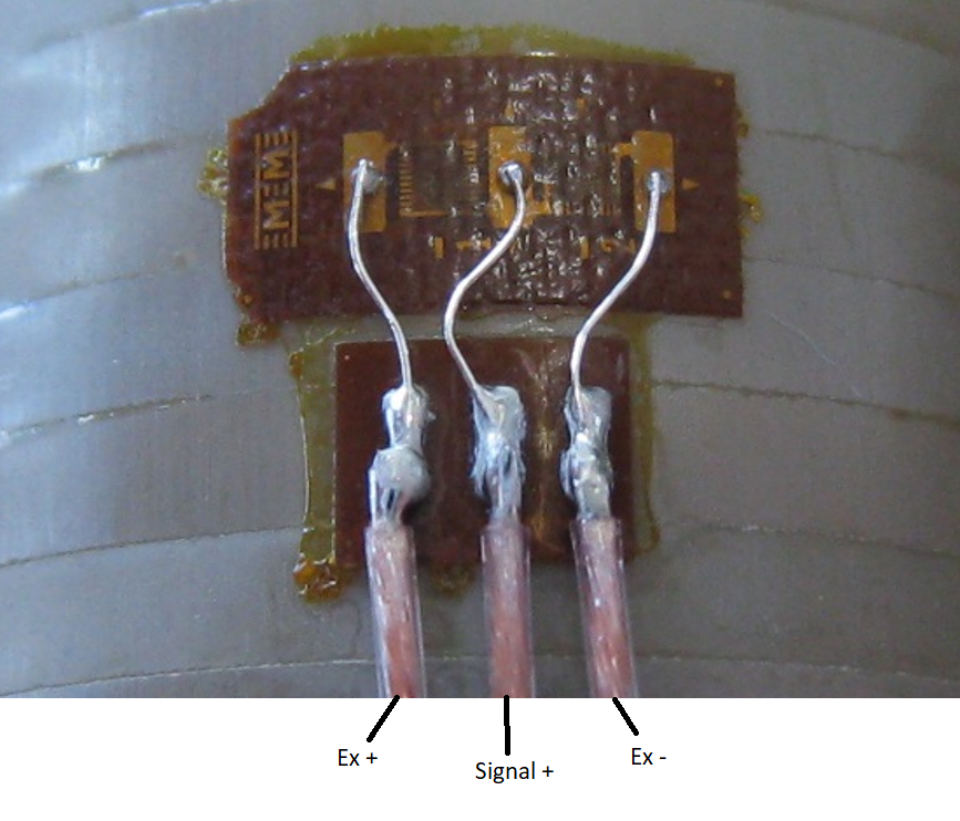
b. During the assembly we did not have vendor data to identify the leads for the strain gauge, hence we connected the wires based on the spare units at CIT (which lead to some confusion as the two spare units internal wiring contradicted each other). As per D2000382, the bridge excitation should be connected to pin 1 on the might mouse connector and GND should be at pin 3, strain signal on pin 6. In reality we connected the GND to pin1, strain signal to pin6 and +V bridge excitation to pin 3 (basically pin 1 and pin 3 are inverted). Later (post assembly), Camille acquired the vendor data for identifying the leads for the strain gauge, which is shown here. After discussing this with Jeff Kissel and Daniel, we concluded that this should not affect the working of the SG - however for future assembly we should use the latest vendor data.
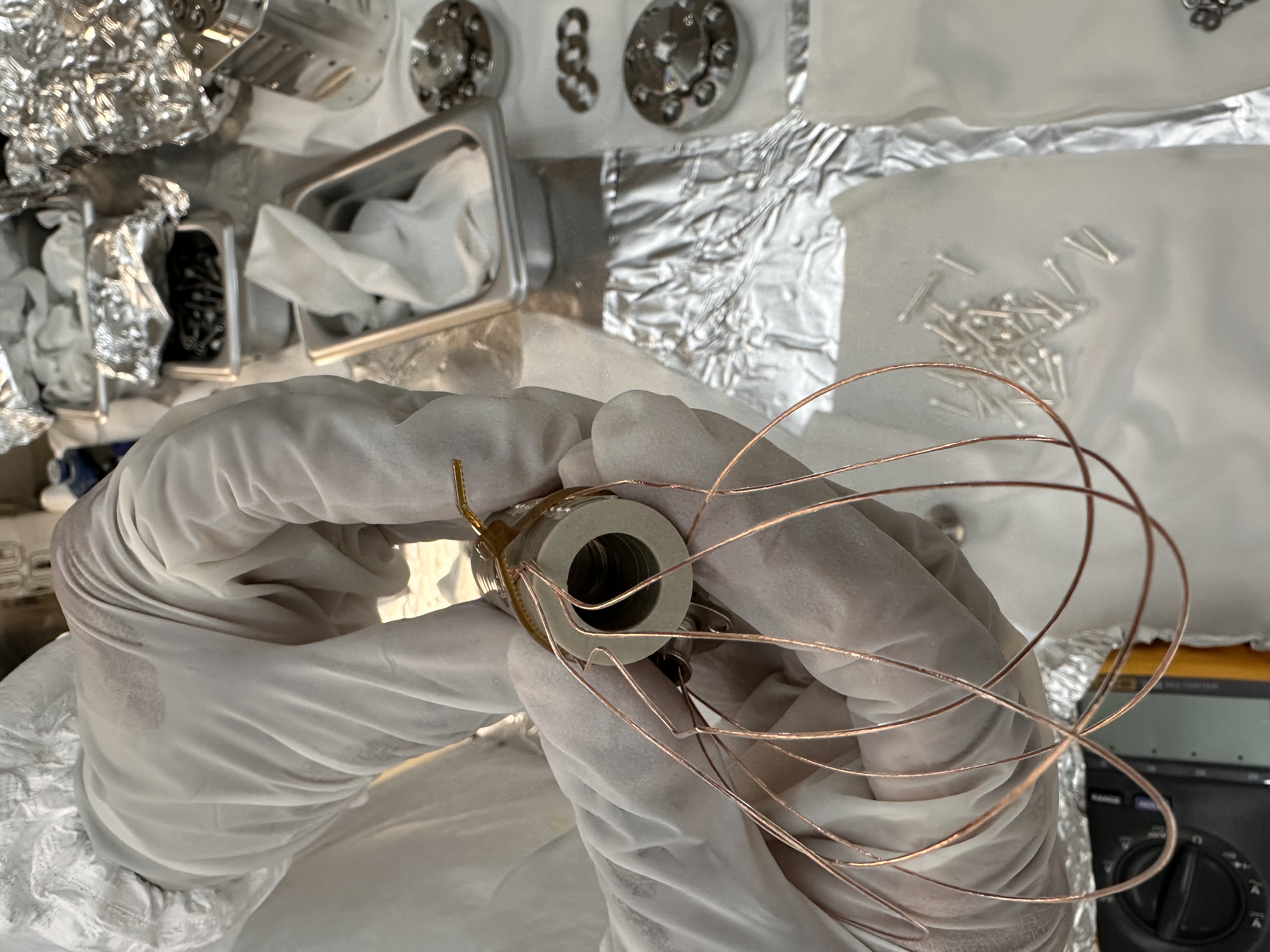
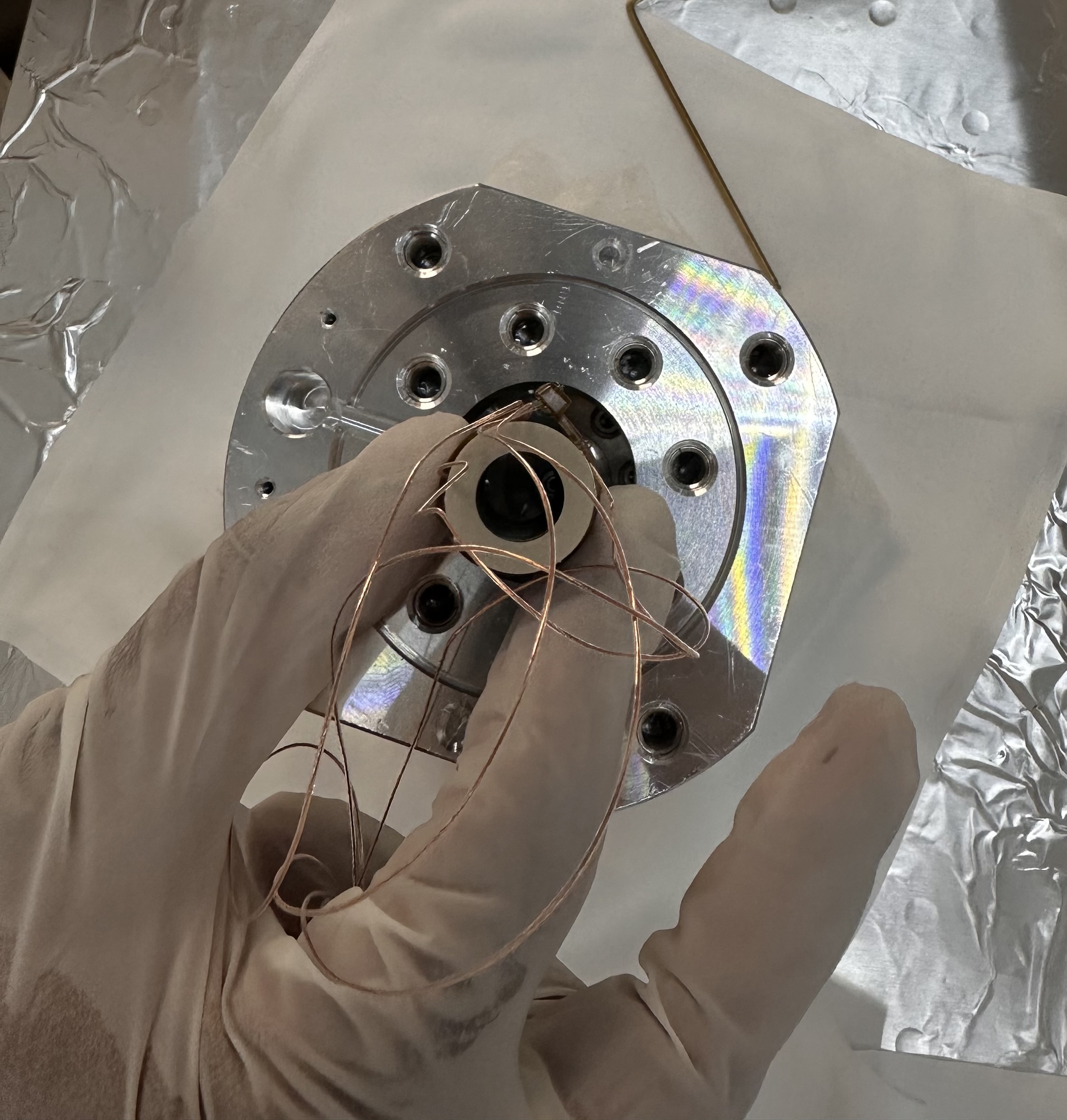
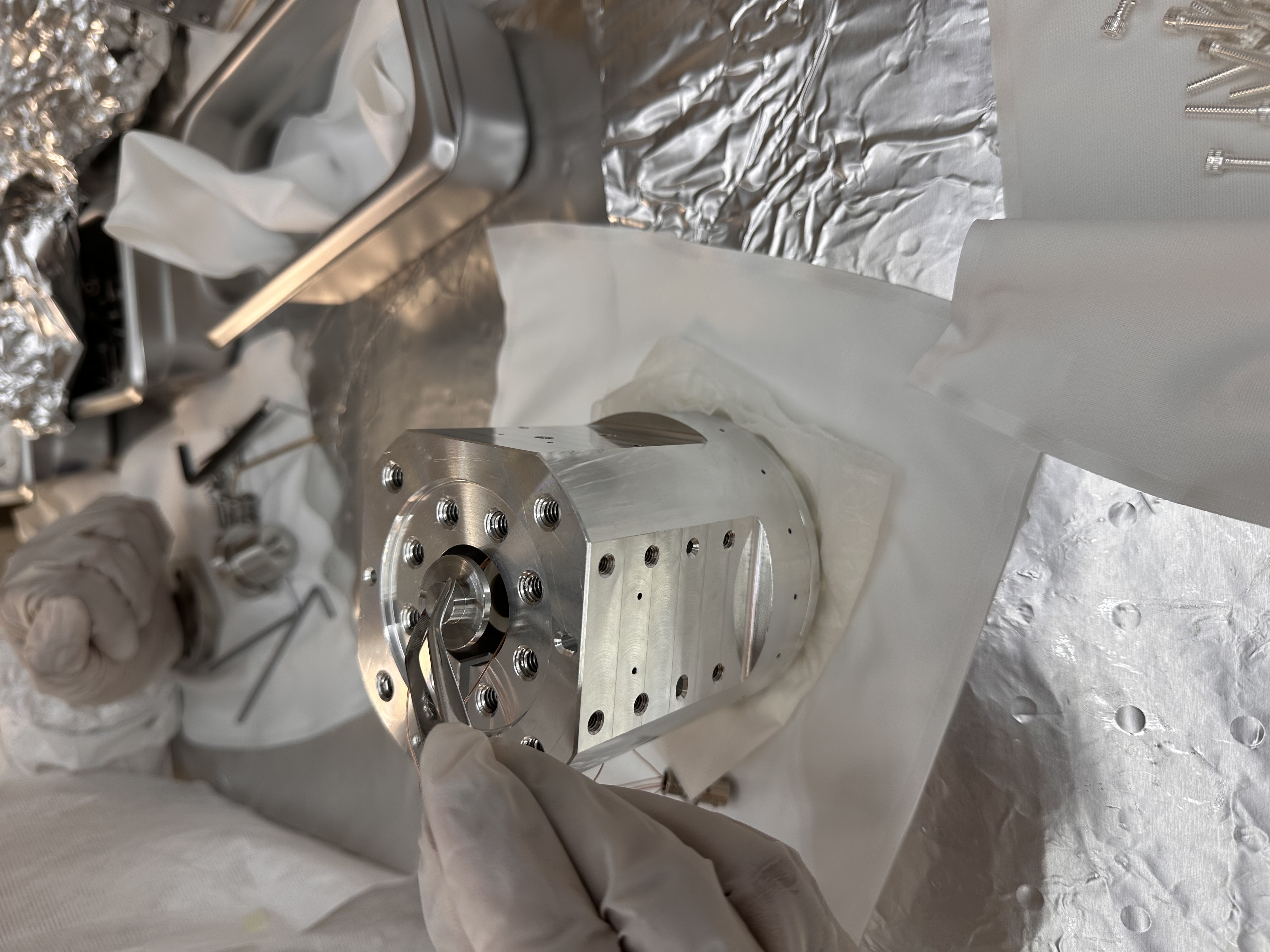
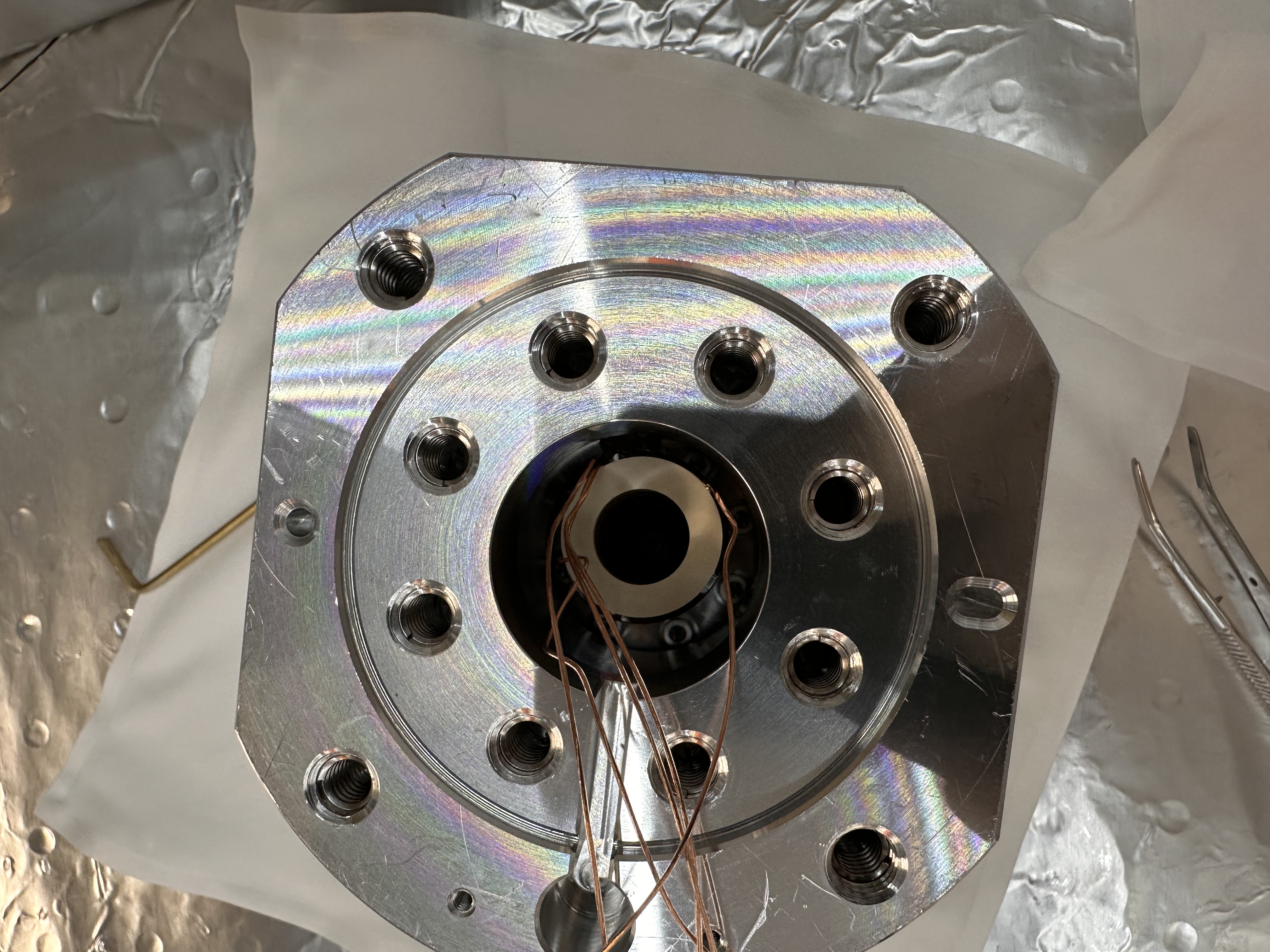
c. The PZTs, washers and the deformable mirror were all stacked vertically (as per T2400260) and torqued as per specification - see pictures for reference here - attachment05, attachment06, attachment07, attachment08 and full assembly shown in attachment09.
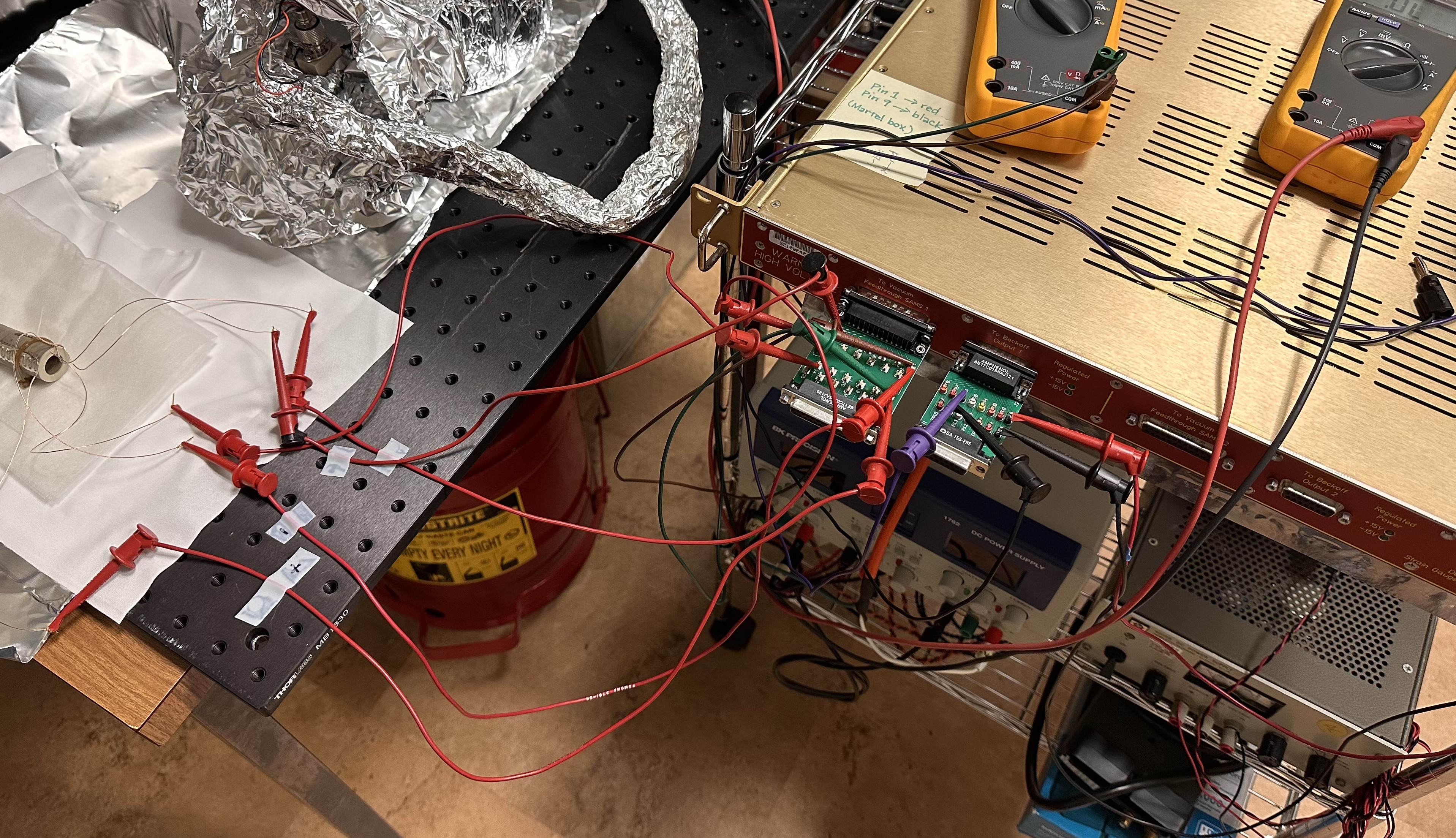
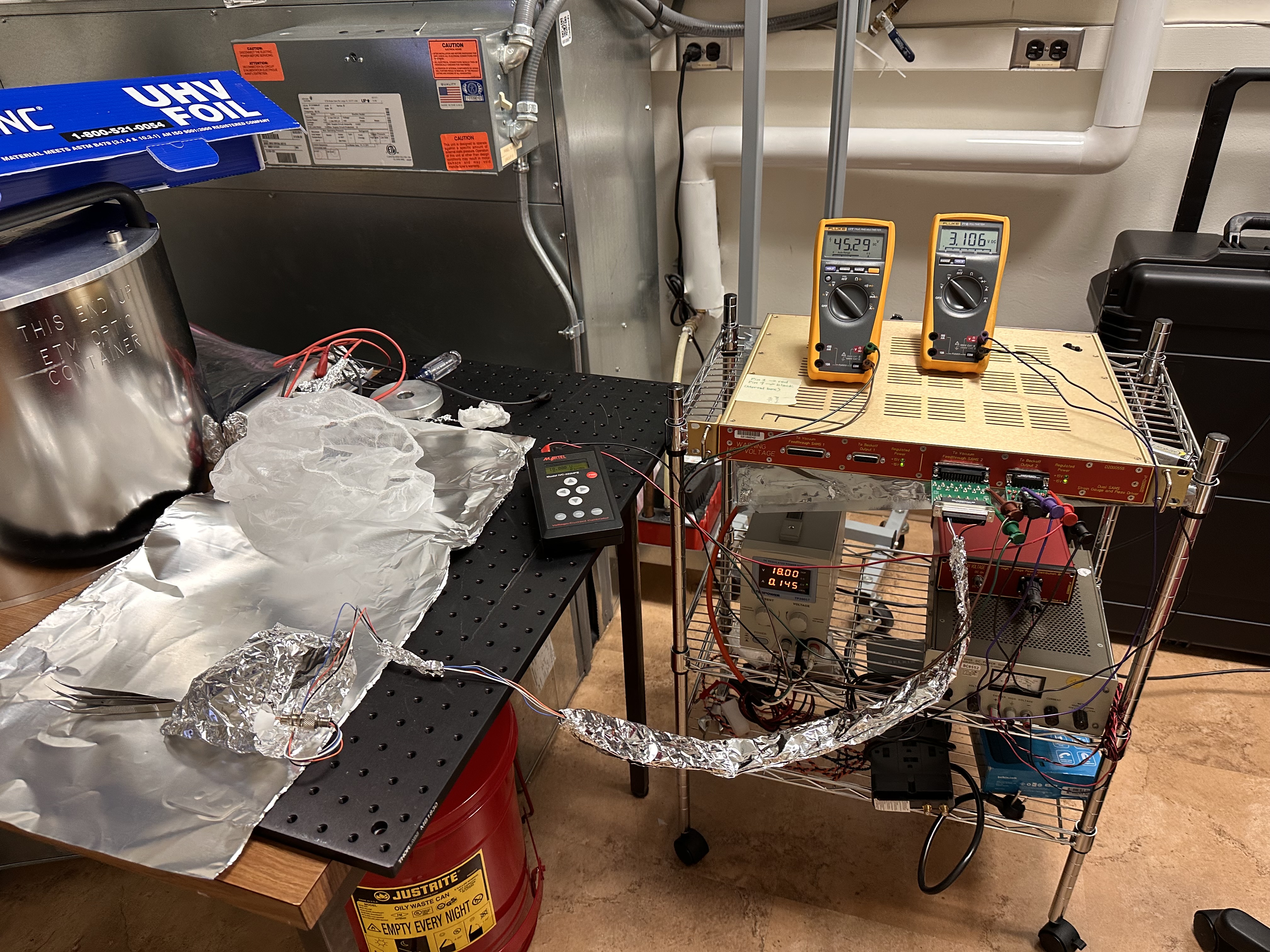
d. Electrical testing - we followed E2100371 to confirm the electrical connections for the PZT voltage and strain gauge readout - test set up shown in attachment10 and attachment11.
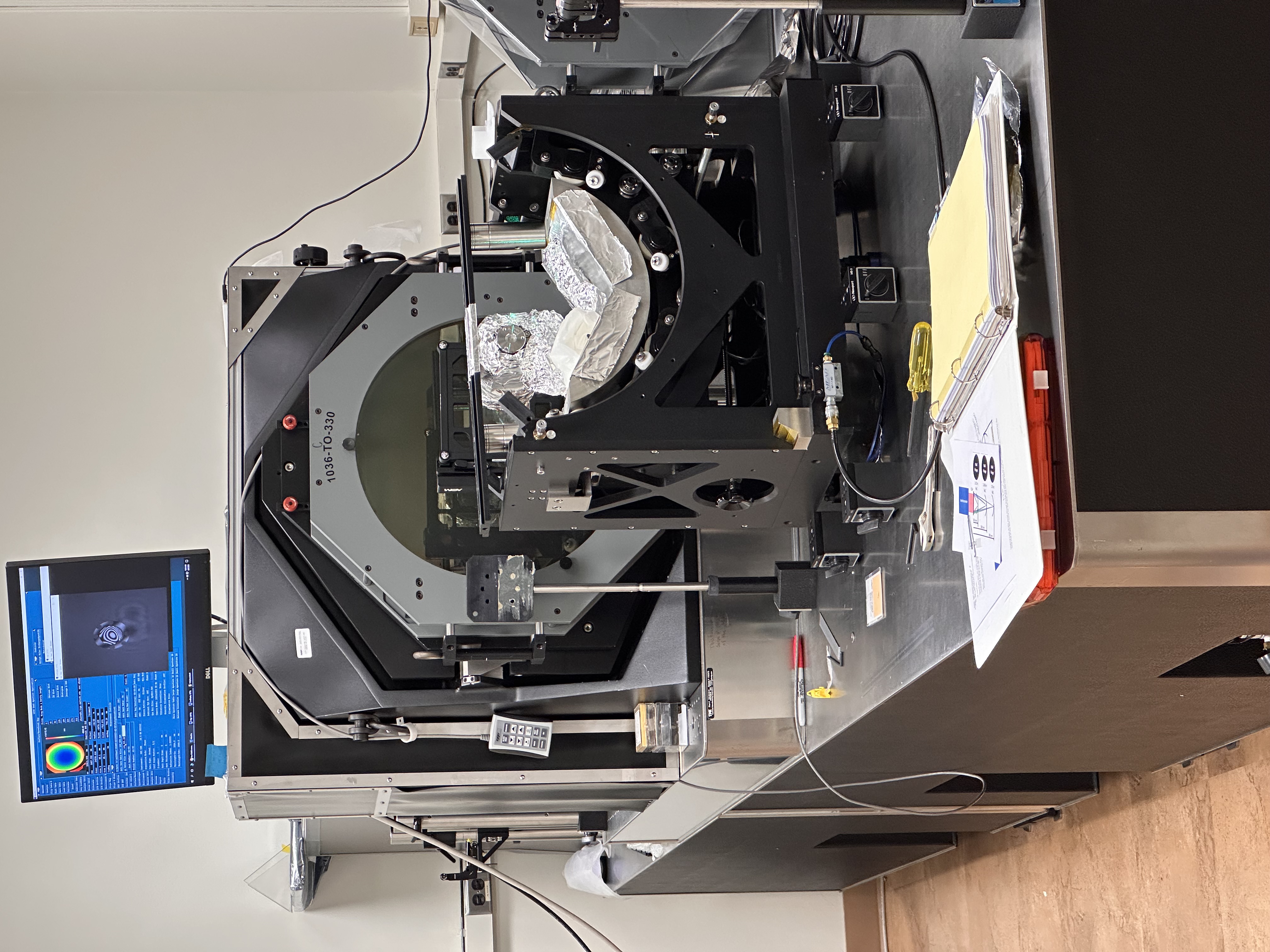
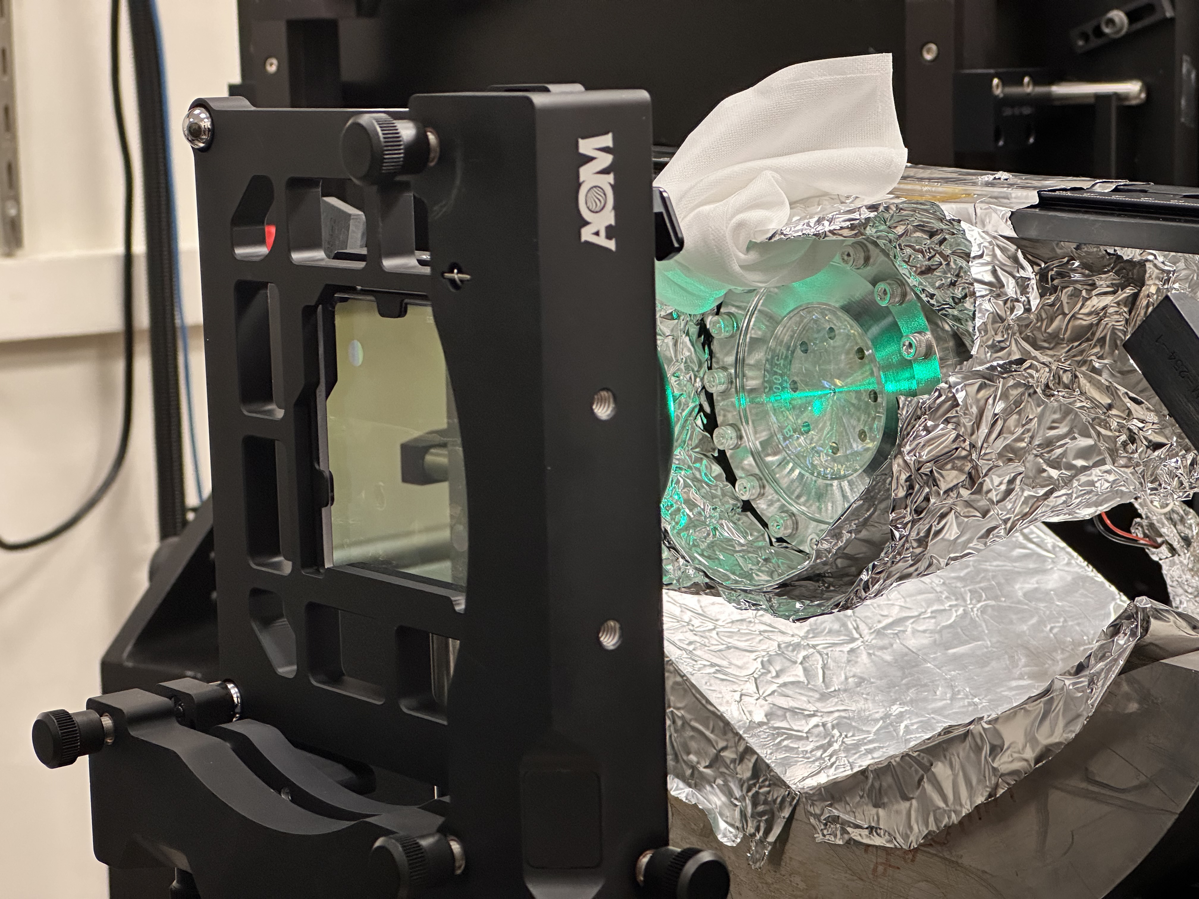
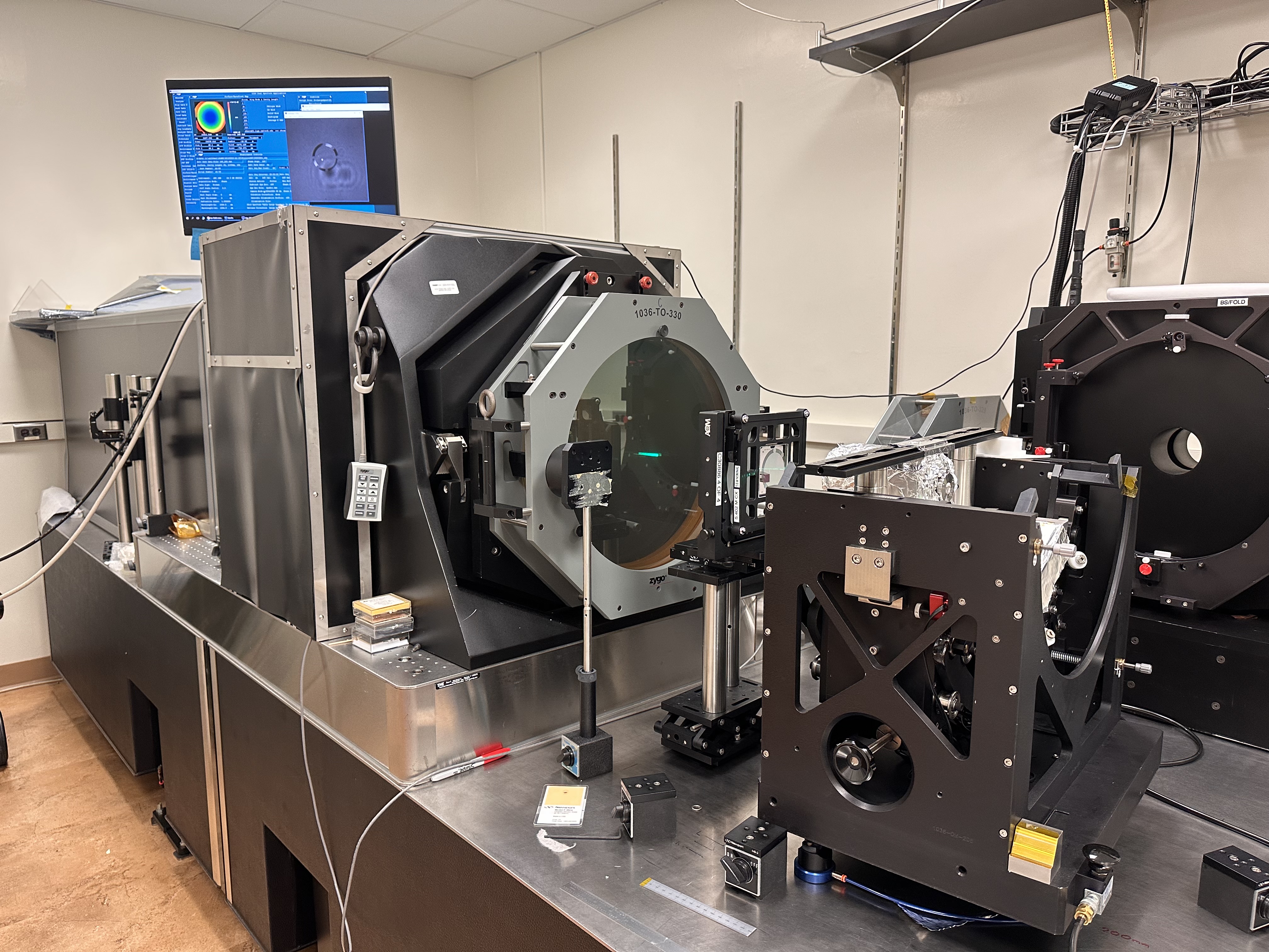
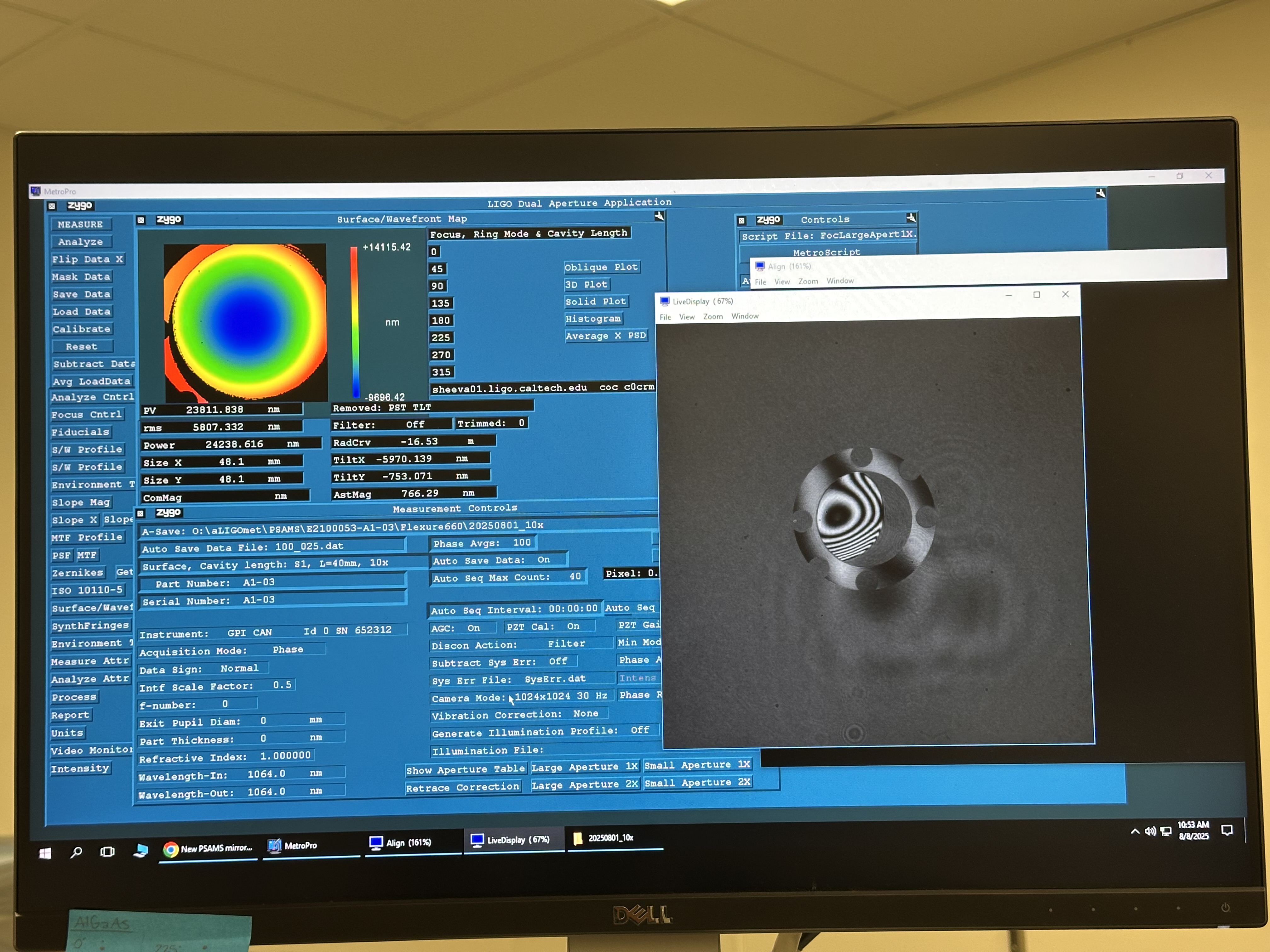
e. RoC measurement on ZYGO interferometer - after successfully testing and confirming the working of the PZT actuation we started measuring the Radius of Curvature (RoC) of the optic on the ZYGO interferometer - see attachment12, attachment13 and attachment14 for details of the setup - fringes observed as shown here, as an example. The final numbers (pre-load and the RoC for each mirror) are posted above.
We wanted to capture few things which we faced during the assembly and testing and this will help for assembling future units. These are listed below,
1. Tangless helicoils for mirror mounting - we used tanged helicoils for mirror mounting, however breaking the tang after the assembly was very unsafe for the mirror. Hence, we had to unmount the mirror from the flexure mirror holder, break the tangs and then re-mount the mirror (which involves heating and cooling them). Hence, we would recommend to use tangless helicoils only.
2. We struggled to attach D1900097 to D1900123 since the threads were bad on D1900097. Don got us a 1''-32 size tap from McMaster to chase the threads, however I could only chase a few of them - enough to assemble four units. The threads on the other 6 units (D1900097) at CIT were extremely difficult to chase hence we included it in our future to-do list of things (might have to be made dirty again for proper chasing).
3. PEEK zip tie for wire lacing inside the PSAMS - the old PSAMS used viton ring to lace the PZT electrical leads, this has now been replaced with PEEK zip tie. We were not very convinced with this, as the viton ring felt easier to use and more secure for the wires.
4. We spent a lot of time trying to understand and interpret the correct wiring diagram - initially Fabrice's FDR and Luis's document contradicted each other. To add to the confusion, the already built unit at CIT (two spare psams, with two different cables and might mouse connections) wiring also contradicted each other. However (long story short), after talking to Fil and Marc at LHO we were able to sort it. We had to change the 18V power supply to the PZT driver D2000555, since the exciting one was faulty. Also, Dean (at CIT) made some quick checks on the PZT driver to confirm that it was healthy. However the most important thing to note over here is as follows - the two spare units at CIT, ZM2 and ZM5 (from the previous build) have wiring diagrams different from the design (I think for ZM2), hence this needs to be checked before future use.
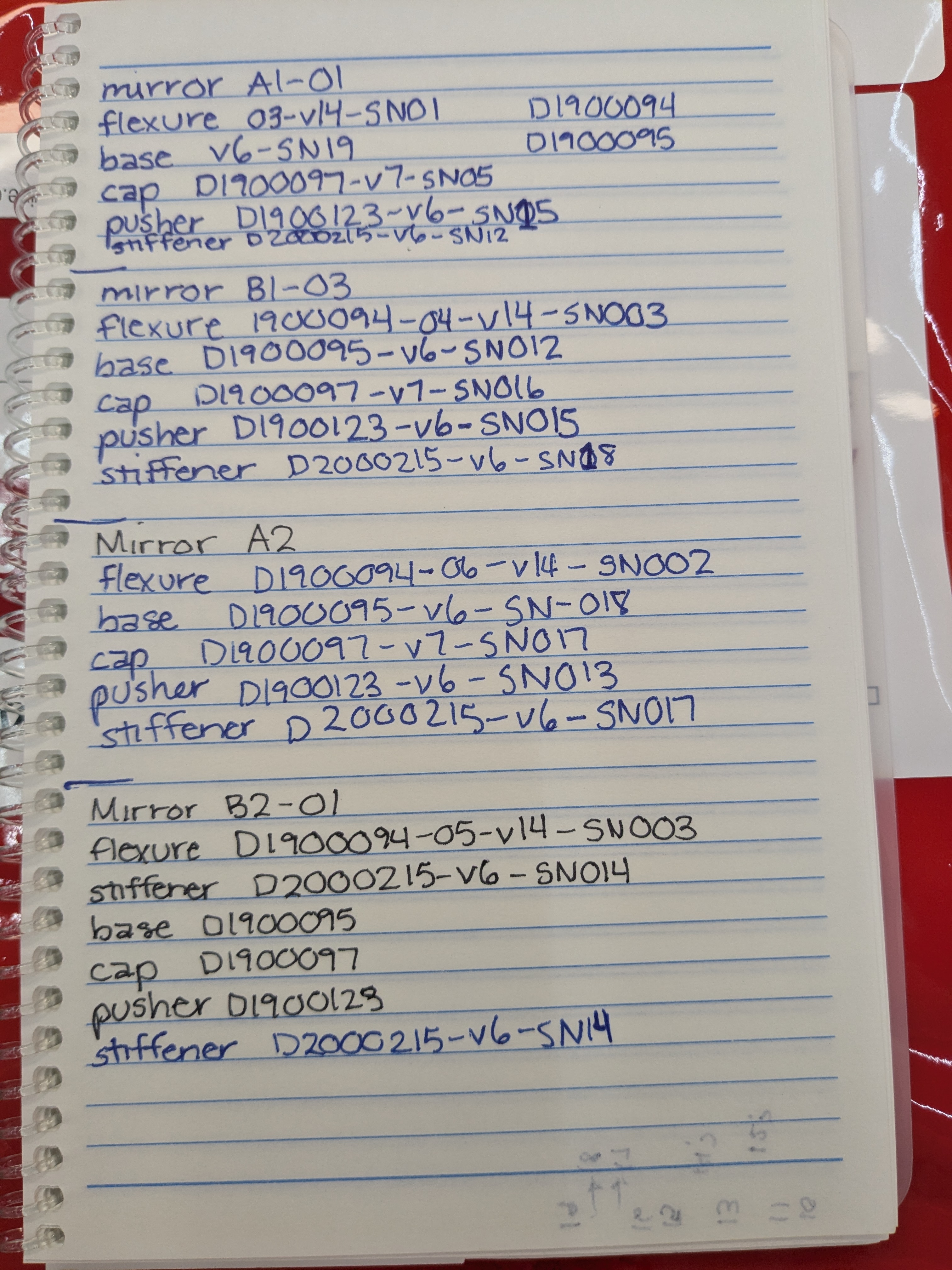
Camille as noted down the serial number of the parts used during this assembly and they are listed here.