Jennie W, Rahul K, Keita K
Executive Summary: The measurements of ISS input beam dither coupling to the PDs need repeated as their may be some settings on the oscilloscope we didn't setup properly.
Measurement Theory:
To get a coupling measurement of the ISS diode array to input beam motion we need:
AC measurement for each of the 8 diodes (ACPD1, ACPD2, etc.).
simultaneous AC measurement for the X and Y channels of the QPD (X, Y).
We have a calibration measured previously that tells us that the QPD calibration [Cal] is 45 V/mm when the input beam is dithered horizontally, and that the direction we dither the beam in is 14.9 degrees from the X axis of the QPD (presumably because the QPD is not quite aligned rotationally in its support).
To work out the movement in the actual horizontal plane on the QPD (R_QPD) we use:
Mag = sqrt(X^2 + Y^2)
theta = atan2(Y, X)
R_QPD = Mag * e^(i*theta)
Average DC voltage for each of the 8 PDs to normalise the coupling measurement (DC1, DC2, etc)
Coupling = (AC PDn / DCn)/ (R_QPD/Cal)
When Mayank and Shiva were here we were doing this measurement using the average and peak to peak values for the voltages of DC and AC signals respectively. This throws away the phase info, so now we are trying to do this using transfer functions between the motion of the input beam on the QPD and the PDs.
On August 18th we re-aligned the input to the ISS in the optics lab to minimise the coupling to each of the PDs by eye on the oscilloscope traces showing the AC coupled time series.
The dither used to measure the coupling is applied on a steering mirror after the mode-matching lens but before the PBS used to fix the polarisation of the beam.
The dither we used initially was 1Vpp, but we made some effort to reduce noise on the signal by tuning the resistance of the laser temperature controller.
The new dither is 40mVpp at 100 Hz, and has an offset of 2.5V to keep the mirror aligned into the ISS array input aperture.
All three oscilloscopes are synced via a square wave from the signal generator used for the dither and can be controlled by USB hookups to the opticslab PC.
The code to trigger them at once is from the ipython notebook saved on C:\Users\opticslab as meas_TF_osc.ipynb:
import pyvisa
rm = pyvisa.ResourceManager()
import numpy as np
import time
print(rm.list_resources()) ## This command list the available resources
delay = 4 # Allow a delay in query between write and read
scope1 = rm.open_resource('USB::0x0699::0x03A3::C060047::INSTR', query_delay=delay) ## Instantiates the instrument
scope2 = rm.open_resource('USB::0x0699::0x03A3::C042270::INSTR', query_delay=delay) ## Instantiates the instrument
scope3 = rm.open_resource('USB::0x0699::0x03A3::C042275::INSTR', query_delay=delay) ## Instantiates the instrument
scope1.write(f'ACQUIRE:STATE OFF')
scope2.write(f'ACQUIRE:STATE OFF')
scope3.write(f'ACQUIRE:STATE OFF')
scope1.write(f'ACQUIRE:MODE SAMPLE')
scope2.write(f'ACQUIRE:MODE SAMPLE')
scope3.write(f'ACQUIRE:MODE SAMPLE')
scope1.write(f'ACQUIRE:STOPAFTER SEQUENCE')
scope2.write(f'ACQUIRE:STOPAFTER SEQUENCE')
scope3.write(f'ACQUIRE:STOPAFTER SEQUENCE')
scope1.write(f'ACQUIRE:STATE ON')
scope2.write(f'ACQUIRE:STATE ON')
scope3.write(f'ACQUIRE:STATE ON')
All this does is trigger the scopes, the channels have to be turned on manually and saved manually. Francisco has worked on a much better bersion of this code but I haven't had time to test it yet.
The data we gathered on the 18th is shown below.
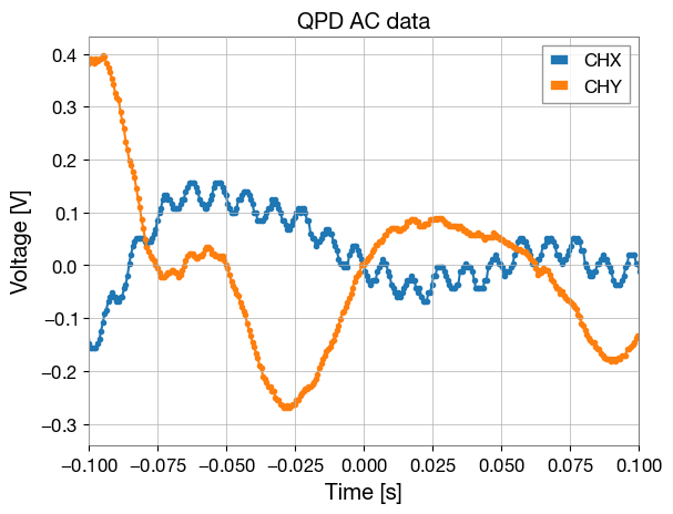
The time series for X and Y is shown here.
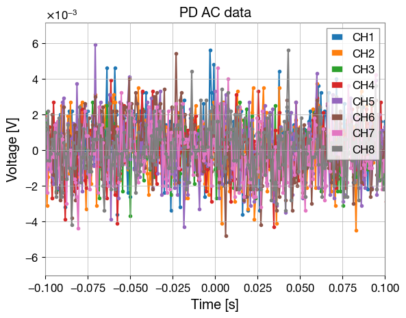
The time series for ACPD1-8 is shown here.
One can not really see a coherence, this could mean the array is perfectly aligned, but this is not likely as we have not done very fine adjustments.
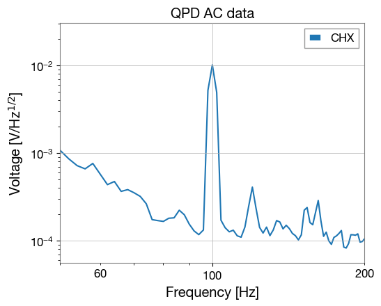
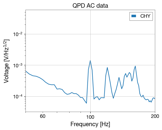
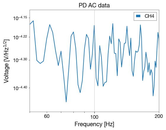
This is more obvious if one looks at the ASD of each of the PDs, I have just attached one of these but none of them show a signal above the surrounding noise at 100 Hz where the injection was.
We are seeing this signal on the X and Y ASDs.
The csv files I saved for AC, DC and QPD all had different time steps, but the same span meaning they were all different lengths. We might need to retake this data and mess around with the display and save settings to fix this - Keita investigated earlier today and it is possible to change the save resolution to be larger and also to reduce the number of samples the oscilloscope saves via the trigger menu.
I might also try to increase the dither amplitude if this still doesn't help us do the measurement.
Once we have this measurement working we will need to iterate this measurement a few times while making small adjustments to the alignment into the array and possibly moving one or more of the PDs in their mounts.
The next steps are to repeat this measurement for vertical dither and then to do beam scans across each PD to see how well centred they are with respect to the beam.