leendert.schrader@LIGO.ORG - posted 14:05, Friday 22 August 2025 (86521)
Summary of SURF 2025 Project: Leo Schrader
Leo, Camilla, Jennie W.
Over the summer, a robust mode-matching simulation for the SQZ beam to the OMC was built using the a la mode library. This report serves to summarize the current state of the simulation and the relevant information one can extract from it.
Link to git code: https://git.ligo.org/leendert.schrader/alm-beam-simulation-for-sqz/-/tree/main SQZ_simulation_v4.m is currently the most recent version.
#1 A detailed description of the squeezed beam path.
Distances, curvature radii, incidence angles, refractive indices, etc. are all within the code file with comments on where they were obtained. This includes all information necessary to propagate the beam starting at the SQZ output (BM4), through ZM4-6, the OFI, SRM, and into the OMC.
These can also be found in the google doc in T2500228, though the curvature radii for ZM4/5 are not what are used in the simulation.
Related aLogs: 85282, 85339
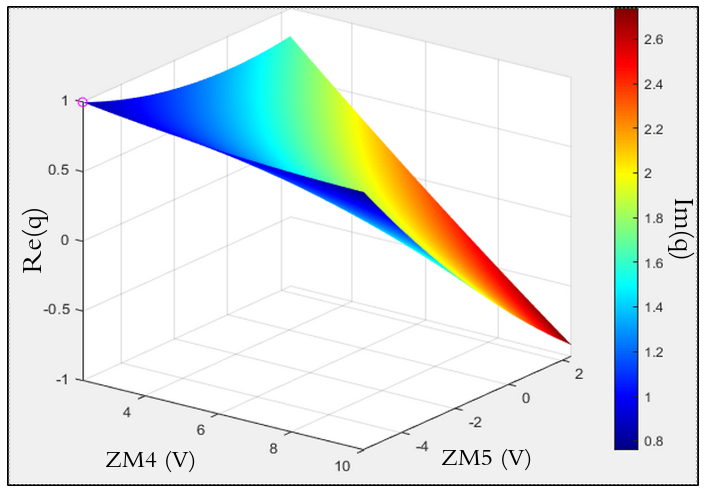
#2 The beam characteristics between ZM5 and ZM6.
Using the beam profiling data from SQZT7 one can plot a "q manifold" which assigns a q parameter with respect to strain gauge values for ZM4 and ZM5.
That is, if one knows the strain gauge for ZM4/5, they can know the beam after ZM5.
Attached is a sample of the q manifold obtained by fitting the horizontal beam width data.
Related aLogs: 85917, 86365, 86519, 85775
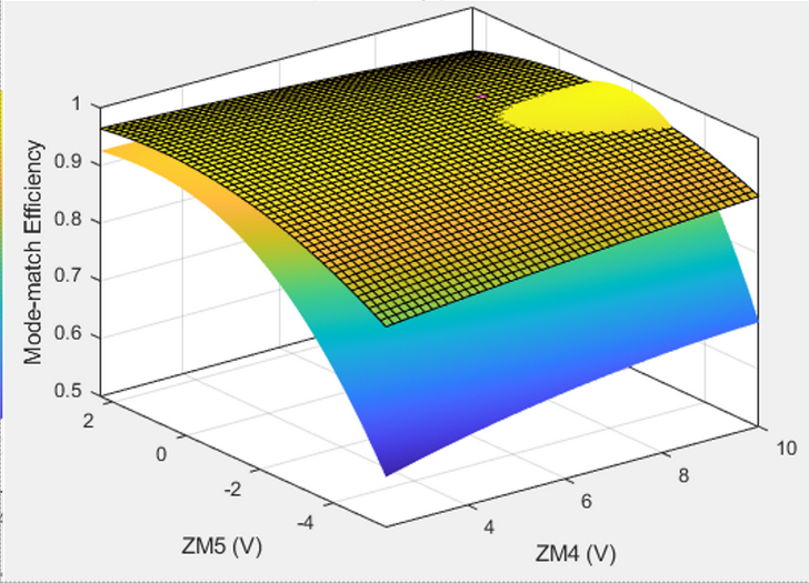
#3 Simulated and experimental mode-matching at the OMC.
Simulated: By Propagating the q manifold forward to the OMC using the beam path constructed in a la mode, we can simulate mode-matching with respect to ZM4/5 strain gauge values. The simulation was found to be accurate for high mode-matching, but underestimates matching on the fringes of the strain gauge ranges (compared to collected data).
Experimental: Multiple OMC scans for mode-match were obtained, which allows us to characterize mode-matching across any strain gauge values for ZM4/5.
Attached is a picture of both the simulated and experimental matches against each other. The surface with a grid fits the experimental data, while the surface without grid is the simulated data.
Related aLogs: 86445, 86467, 86520
#4 ZM4 and ZM5 curvature estimates.
We estimate ZM4 curvature by interpolating data in E2100289. Note that preload was increased from 46 in lb to 75 in lb, hence why we had to "interpolate."
We predict the curvature of ZM4 acts as
R_ZM4 = 2/(-0.026296*V_ZM4 - 0.310465)
where V_ZM4 is the strain gauge value for ZM4.
This equation is achieved by assuming a linear voltage - to - optical power relationship (hence the '2 divided by a linear term'). The q manifold is then used to predict the ZM5 curvature values.
Therefore, by ranging the strain gauge in the simulation GUI, one can find simulated ranges for ZM4 and ZM5 curvature.
Note: ZM4 was selected for the above estimate, as we found it behaved "more linearly" than ZM5.
Miscellaneous: the simulation contains the unique SRM ray transfer matrix in the M_SRM variable (see the first interim progress report in T2500228 for details on computation).
For all reports and presentations related to the summer project, see the main DCC document T2500228.
Images attached to this report