With help from E. Bonilla, M. Todd, and S. Dwyer
Some background:
The HARD loop open loop gain transfer function can provide information about the arm power. The radiation pressure within the arm cavity adds an additional torsional stiffness term that stiffens the hard mode and softens the soft mode, causing the eigenmodes of the suspension to shift up (hard mode) or down (soft mode) in frequency.
We can measure this shift in frequency by taking the open loop gain of the hard loop, and dividing out the known digital controller to measure the high power plant hard plant.
The highest frequency pole in the suspension plant is the most interesting to study, as this is the hard mode that is most susceptible to the arm power. Edgard's technical document on the Sidles Sigg modes in the BHQS, T2300150, gives a good explanation as to why. Note that his document covers the BHQS design, which differs from the QUAD design in several respects, but the underlying physics is the same. Figure 2 on page 3 demonstrates the behavior of the suspension eigenmodes with respect to increasing intracavity power, demonstrating that the highest frequency hard mode will shift in frequency the most compared to the other modes (the opposite is true for the soft mode). Figure 2 will appear different for the QUAD model in pitch due to the large cross coupling of length to pitch (which mixes length modes into the shifting as well, yuck).
Some equations:
Following his document, we can use Equation 4 as a first order approximation for the hard mode frequency:
f_hard = 1/2*pi * sqrt(k_4 + k_hard / I_4)
where k_4 is the torsional stiffness of the fourth eigenmode of the QUAD, k_hard is the torsional stiffness induced by the radiation pressure torque and I_4 is the moment of inertia of the fourth eigenmode of the QUAD.
k_hard can be shown to depend on arm power via:
k_hard = P_arm *_L_arm / c * gamma_hard
where gamma_hard = ((ge + gi) + sqrt((ge - gi)^2 +4)) / (ge*gi - 1)
and P_arm is the arm cavity power, L_arm is the arm cavity length, and ge,i is the g factor of the ETM or ITM (ge,i = 1 - L_arm / Re,i)
The arm power will then depend on the following:
- measured frequency of the hard mode, which we measure from the OLG (f_hard above)
- suspension moment of inertia and torsional stiffness (without power). this can calculated from the QUAD model (k_4 and I_4 above)
- arm cavity geometry, which is defined by the radii of curvature of the test masses and the arm length (ge and gi above)
The last point is what makes this measurement somewhat degenerate; we know that the radii of curvature of the test masses changes from the design value due to the applied ring heater power and the absorbed power from self heating. However, Matt has been working lately to understand what these values are by checking the higher order mode spacing and finesse models. If we use the higher order mode spacing, and known measurements of the absorbed power from the ITM Hartmann wavefront sensors, we can remove some of the degeneracy.
Esimating the test mass RoCs:
In alog 86107, Sheila estimates the location of the X and Y arm higher order modes:
- using the 10 kHz modes, she finds the X arm modes at 10615 Hz and 10565 Hz (the presence of these two modes suggests astigmatism), which we can average, and then divide by 2 to get the mode spacing
- using the 5 kHz modes, she finds the Y arm modes at 5345 Hz and 5182 Hz (again the two modes suggest astigmatism), which we can average
Using ge*gi = cos^2(pi*f_HOM/FSR) I find that the ge*gi for the X arm is 0.8158 and the Y arm is 0.8178
Matt reports that the ITMX absorbed power is 160 mW and ITMY is 140 mW. His new estimate for the coupling of the self heating is -20.3 uD/W for the ITMs (G2501909, slide 11). The ITM radius of curvatures are reported on galaxy as 1940.3 m for ITMX and 1940.2 for ITMY.
The ITM defocus when we are in the hot state can be calculated via
D = Dc + B * P_rh + Ai * P_self
where Dc = 1/R_cold, B is the ring heater coupling factor in D/W, P_rh is the known ring heater power applied to the test masses, Ai is the coupling above, and P_self is the absorbed power reported above
This gives the hot RoCs for the ITMs as 1949.94 m for ITMX and 1950.96 m for ITMY.
Using the product of the g factors above, we can then estimate the hot RoCs for the ETMs as 2246.54 m for ETMX and 2243.08 m for ETMY.
Calculating the arm power:
These numbers give the following g factors:
| Mirror | g factor |
| ITMX | -1.0485 |
| ITMY | -1.0474 |
| ETMX | -0.7781 |
| ETMY | -0.7808 |
Using the QUAD model parameters I found in /ligo/svncommon/SusSVN/sus/trunk/QUAD/Common/MatlabTools/QuadModel_Production/h1itmy.m and some help from Edgard, I found:
| I_4 | 0.419 kg m^2 |
| k_4 | 19.7118 Nm |
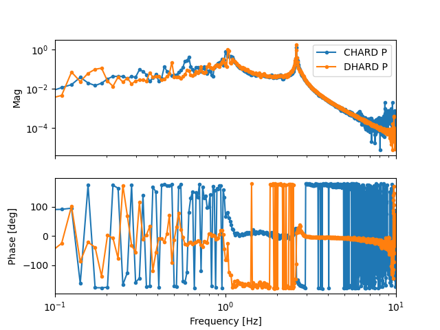
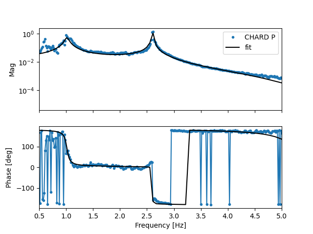
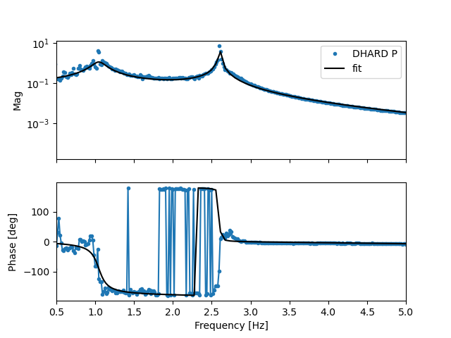
I remeasured both the CHARD pitch and DHARD pitch transfer functions. I divided out the current controllers and used the InteractiveFitting program written by Gabriele to fit the plant. Both measurements give the same result: f_hard = 2.603 Hz
Combining all of the above numbers gives:
P_arm = 332.1 kW, when using the X arm parameters
P_arm = 328.3 kW, when using the Y arm parameters
To be clear, Sheila and I don't think these are the arm powers in the X and Y arm, since the f_hard value will depend on the average power between the arms in the CHARD and DHARD transfer functions. Instead, these values provide a possible range of arm powers.
I am currently reporting these values without any uncertainty (bad!), since the uncertainty will depend on the measurement uncertainty of the OLG, the HOM spacing, and self heating estimate. Once I have a better sense of all of these uncertainties, I will update here.
Furthermore, there are higher order corrections that can be applied to the estimate of the hard mode frequency. For example, Eq 22 in Edgard's document estimates the additional effect due to the effective spring between the PUM and test mass. However, that estimate is not exactly correct for the QUAD model, since the higher order correction will need to account for the length-to-pitch cross coupling. The yaw model may be simpler to use, so I plan to remeasure the HARD yaw OLGs and use them to calculate another arm power estimate.
Overall, putting this result in the context of our other arm power estimates is interesting:
- We reported an arm power of 364 +- 15 kW in the O4 detector paper, calculated via 1/2 * PRG * arm gain * input power
- My recent attempt to use the SRCL dither measurement method resulted in P_arm_X = 319.6 +- 2.8 kW and P_arm_Y = 303.5 +- 2.4 kW
- Sheila's quantum models favor higher arm power than the SRCL dither results suggest, but the highest arm power requires much larger readout losses.
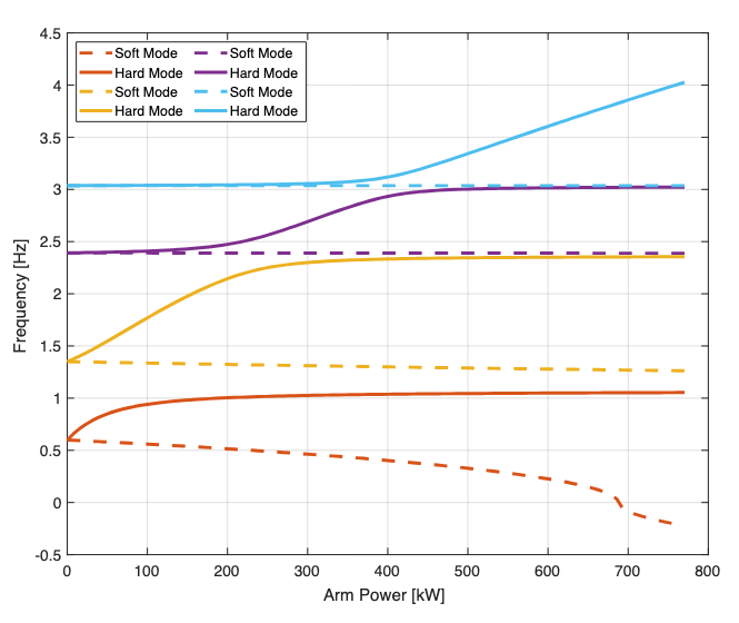
I stated that it may be simpler to use the yaw mode measurement to calculate arm power, however that is not possible. Attached is a figure that demonstrates the hard and soft yaw mode shift with arm power using the QUAD model (Fig 68 in my thesis). We believe we are somewhere in the 300-400 kW region of this plot. At these powers, the yaw hard and soft modes have not been fully decoupled from each other, which means that the approximation that we can use this mode to calculate the arm power is not valid. Edgard's technical document goes into further detail about this approximation. This is validated from the open loop gain measurements I made for DHARD and CHARD Y here, which show that the mode is still near 3 Hz.
However, the pitch mode has fully decoupled, so the values I report above are valid, excepting whatever higher correction is required from length-to-pitch cross coupling.
Incidentally, this probably means we could damp the yaw hard mode from the top mass at this power, but that is an entirely different discussion.