Jennie W, Sheila,
I took a long time to post this as have been working on other things...
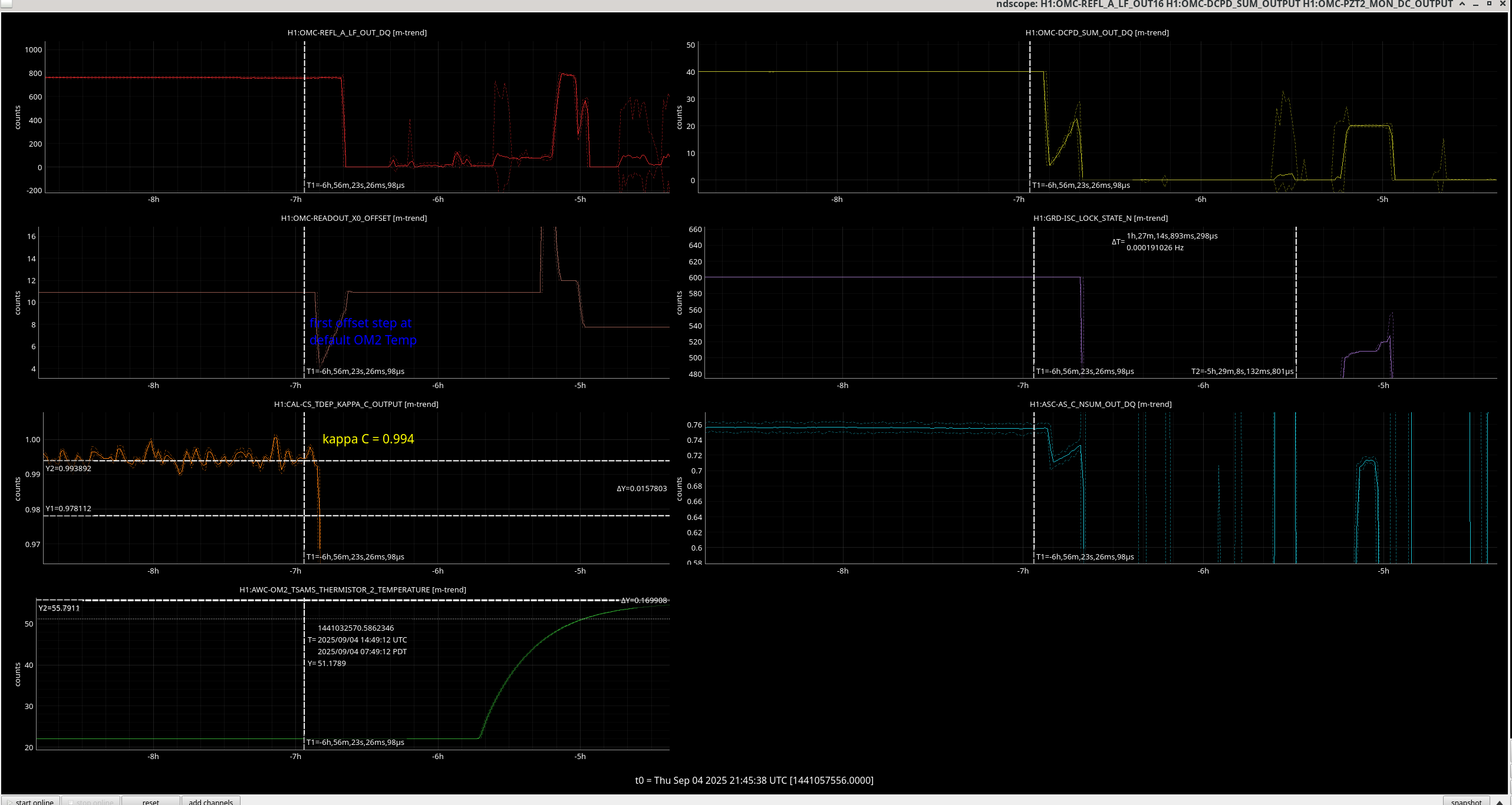
We carried out a test (see LHO alog #86785) to look at the effect of DARM offset stepping on the power at OMC-DCPD_SUMS and OMC-REFL (transmitted through and reflected from the OMC). We did this with the heater on OM2 off as is nominal.
We then meant to redo these measurements once we heated up OM2 to change the mode-matching of the IFO to the OMC.
Unbfortunately we lost lock at about 15:06 UTC while Corey was taking out first measurement before heating up the OM2.
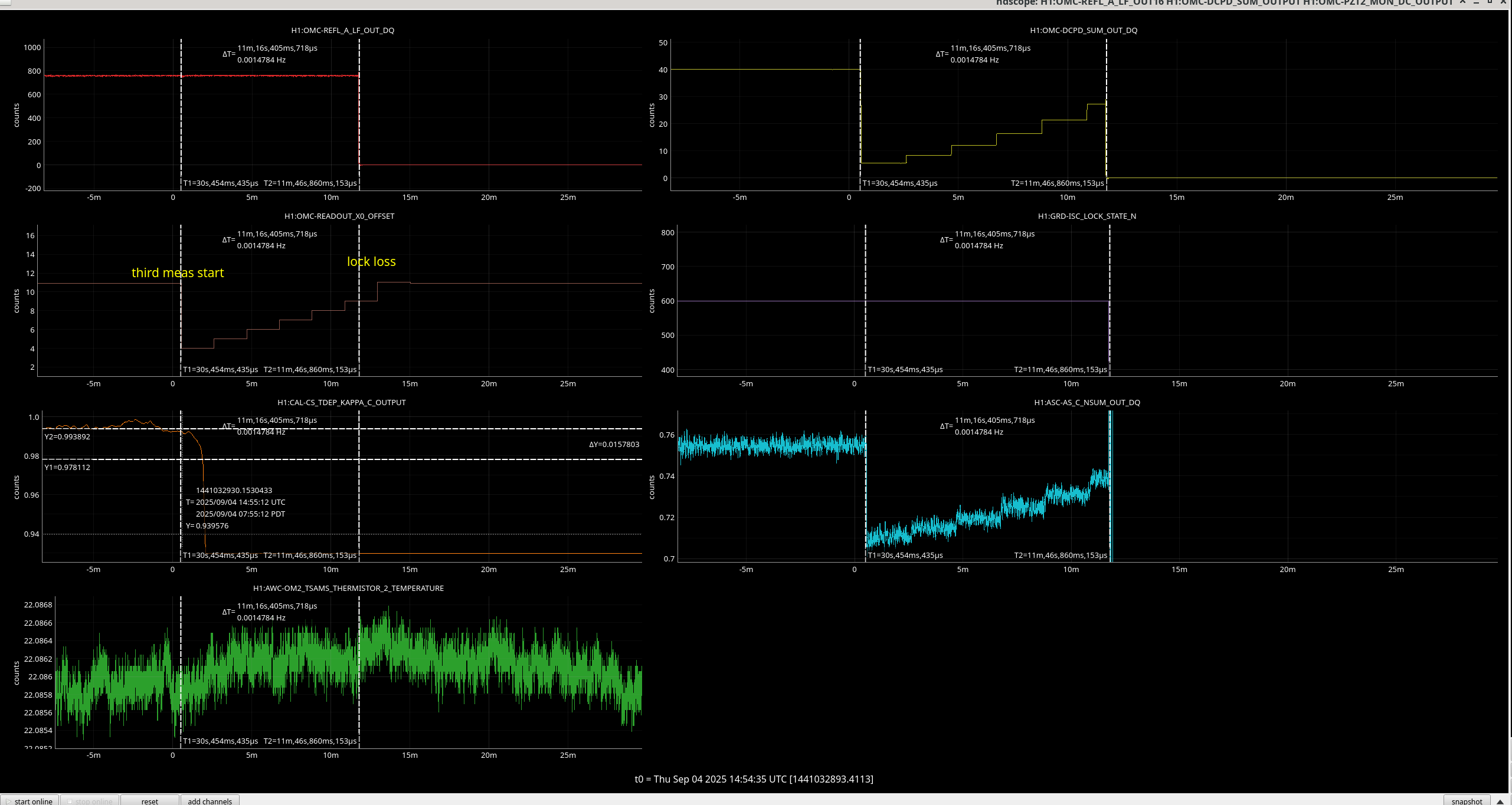
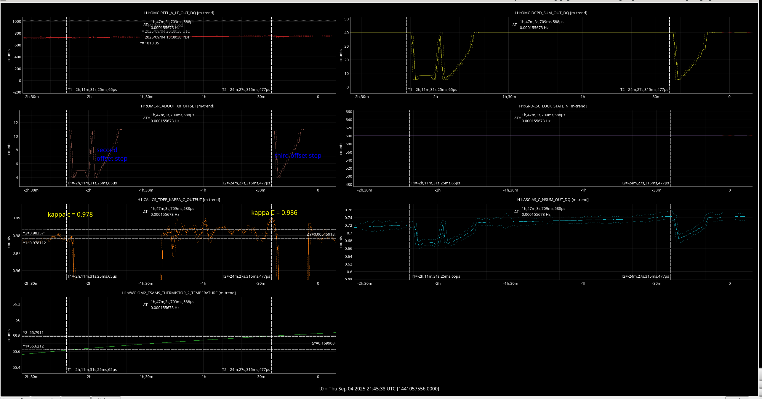
The meausrement is shown in this image, I have mislabelled it as 'third measurement' but it was the first. The optical gain is shown just before this measurment to be 0.994.
Then we waited as long as we could under out initial parameters of being finished cooling the OM2 again by 1:45pm.
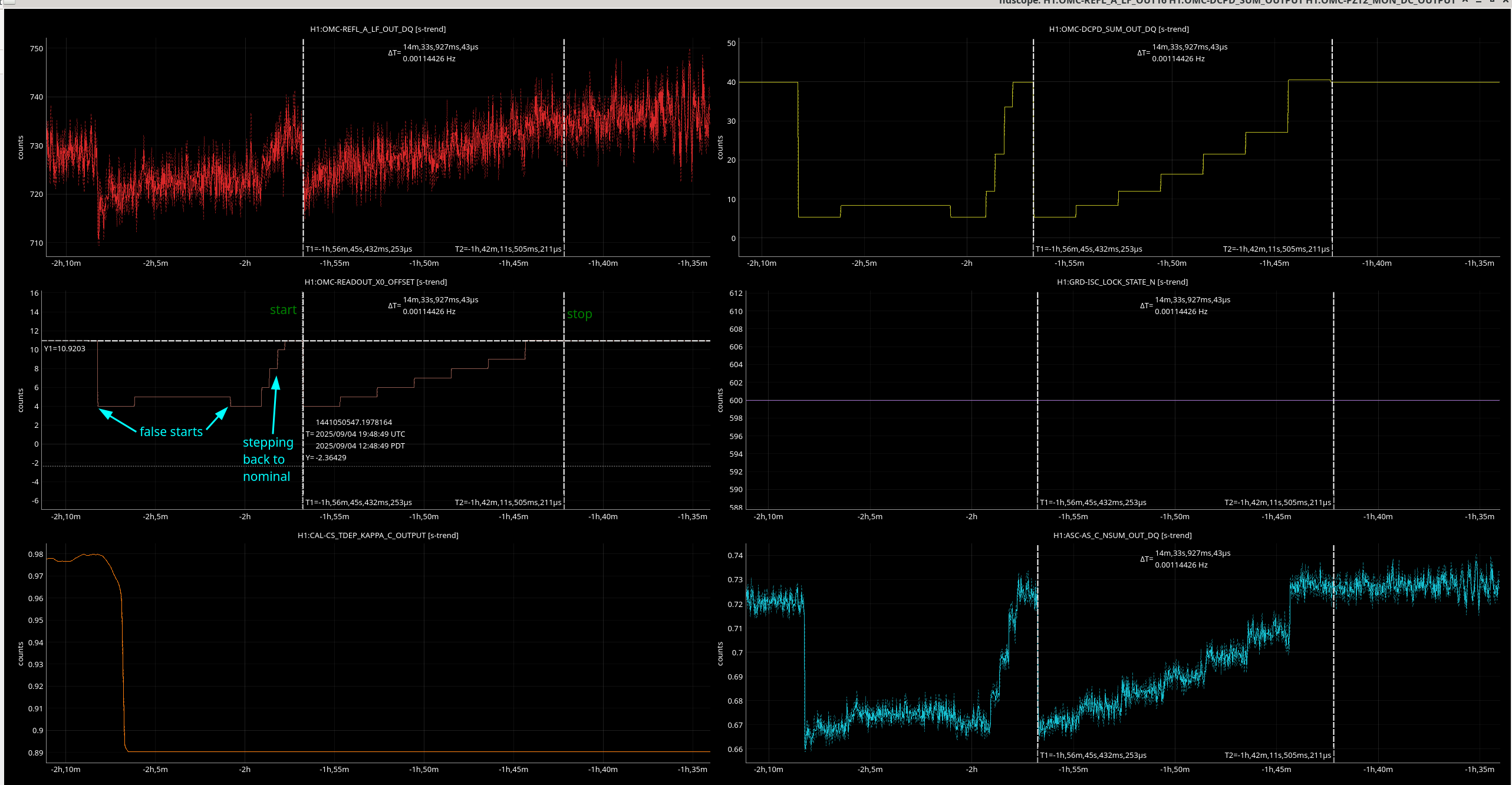
We took another measurement at 1 hr 25 mins into lock after two false starts where I forgot to turn off the ASC. The optical gain was measured right before we started the measurements to be 0.978 but was still thermalising.
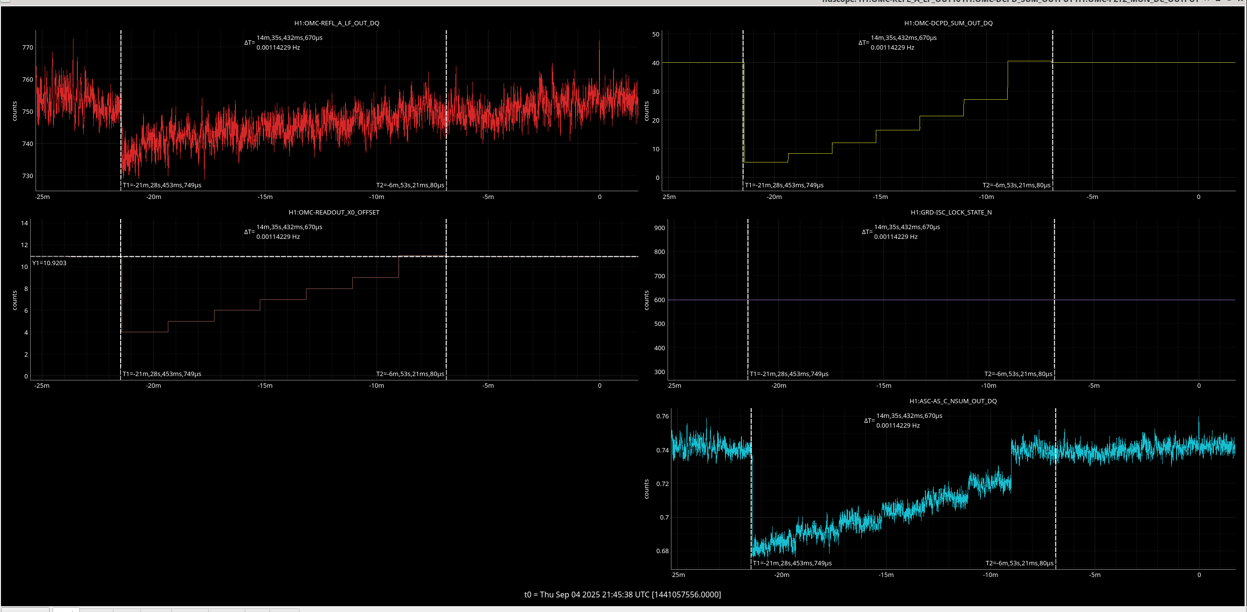
And then we took a third 2 hrs 59 minutes into lock, the IFO should be thermalised but the temperature of OM2 was still trending upwards a bit. Optical gain was 0.986.
We can use the slope of the power at the antisymmetric port (P_AS) vs. the power at the DCPDs (P_DCPD) as the DARM offset changes to estimate the throughput of carrier through the OMC which allows us one estimate of the loss.
The plots of this throughput are here for the cold state (minus the points taken after we lost lock), here for the partially thermalised state, and here for the thermalised state.
I am also in the middle of using the plot of P_AS varying with power at the OMC reflected port (P_REFL) to get a better estimate of the mode-mis match between the interferometer and the OMC.

I plotted the loss between the antisymmetric port (calibrated into the power entering HAM6) to the power on the DCPDs. This is the inverse of the slopes in the graphs above.
All three are poltted on one graph, using plot_AS_vs_DCPD_changes.py in my own cope of the labutils repository at /ligo/home/jennifer.wright/git/local_git_copies/labutils/darm_offset_step/ .
Sheila and Camilla both agreed the loss for the two bottom lines (purple and red) are too high. These imply that a hot OM2 gives us over 20 % output losses.
If we look at the increase in loss from cold OM2 to hot OM2 this is a factor of 2.1 (210 % increase).
Compared to the decrease in optical gain squared (which we expect to reflect the change in output losses, which was:
(0.986^2 - 0.994 ^2) / 0.994^2 = -0.016 (1.6 % decrease).
We might have to check the alignment of out optics was not changing while we changed the darm offset.
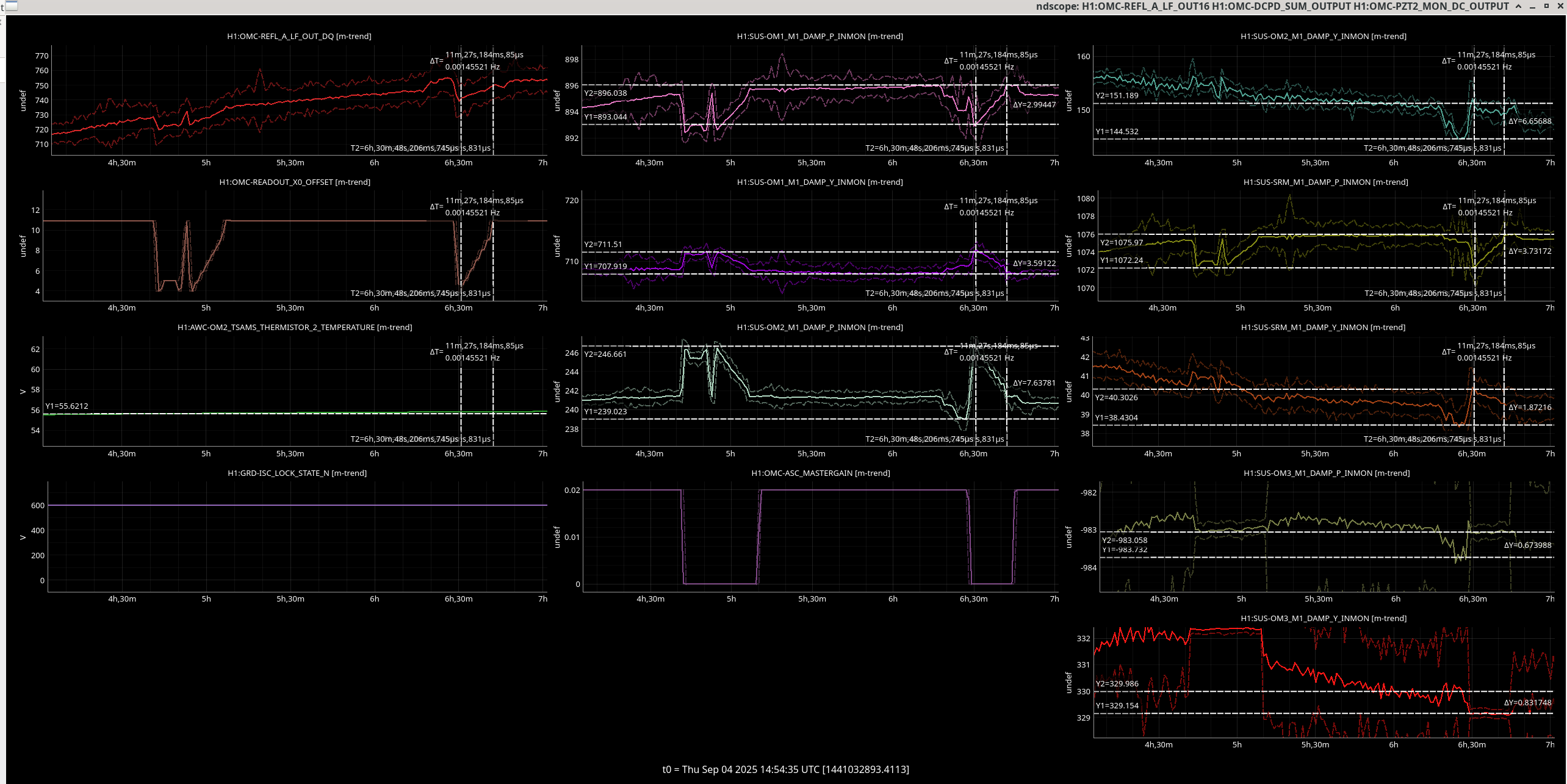
Looking at OM1, OM2 and SRM alignment it did change during the darm offset steps with the biggest change (in the third offsset step measurement) being in OM2 pitch and yaw, this is only a change around 6 microradians (Elenna and Jeff state this calibration in correct to within an order of magnitude). Not sure if this enough to invalidate the loss values we measure. OM3 and OMC sus did not change much but this is because IU purposely unlocked the OMC ASC while changing the darm offset.
Jennie W, Matt T,
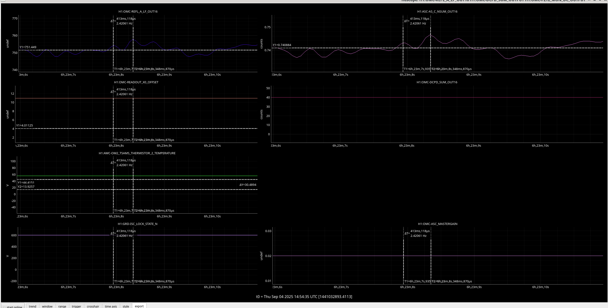
I plotted the antisymmetric power during the darm offset step vs. the power reflected by the OMC and am now very confused as the AS power looks to be smaller than the power reflected form the OMC. See the ndscope where I have zoomed in on the same time segment for both channels. The OMC-REFL channel is mean to be calibrated into mW and the ASC-AS_C channel is meant to be calibrated into W entering HAM 6 (even though the actual pick-off is the transmission through OM1).
The two plots attached show how the ratio between AS and OMC-REFL power changes during one of the DARM offset measurements we did right after I took this ndscope data.
Plot 1 hr 25 mins into lock.
Plot 2 hrs 59 mins into lock.
For each point the code returns the median of the time series at each step, this mioght be less valie for OMC-REFL as it is a lot noisier than ASC-AS_C.
I am still confused about the hogher power at OMC-REFL and wondering if:
a) I am confused about the calibration of one of these channels.
b) the calibration of one of these channels is wrong.
I plotted the three measurements of P_AS vs. P_DCPD during thermalisation on the same plot to make them easier to compare.
The code for this is in /ligo/home/jennifer.wright/git/local_git_copies/labutils/darm_offset_step/plot_OMC_REFL_changes/P_as_vs_P_DCPD__comp_Sep_04.pdf