Camilla, Sheila
We did a series of quick measurements related to filter cavity backscatter, a follow up with plots will come soon.
Injection for linear coupling (varies from day to day, we are repeating to see how much it changes, 1st screenshot):
- /ligo/home/sheila.dwyer/Noise_Budget_repos/excesspowerprojections/data_files/FC_backscatter.xml
- refs 32-34
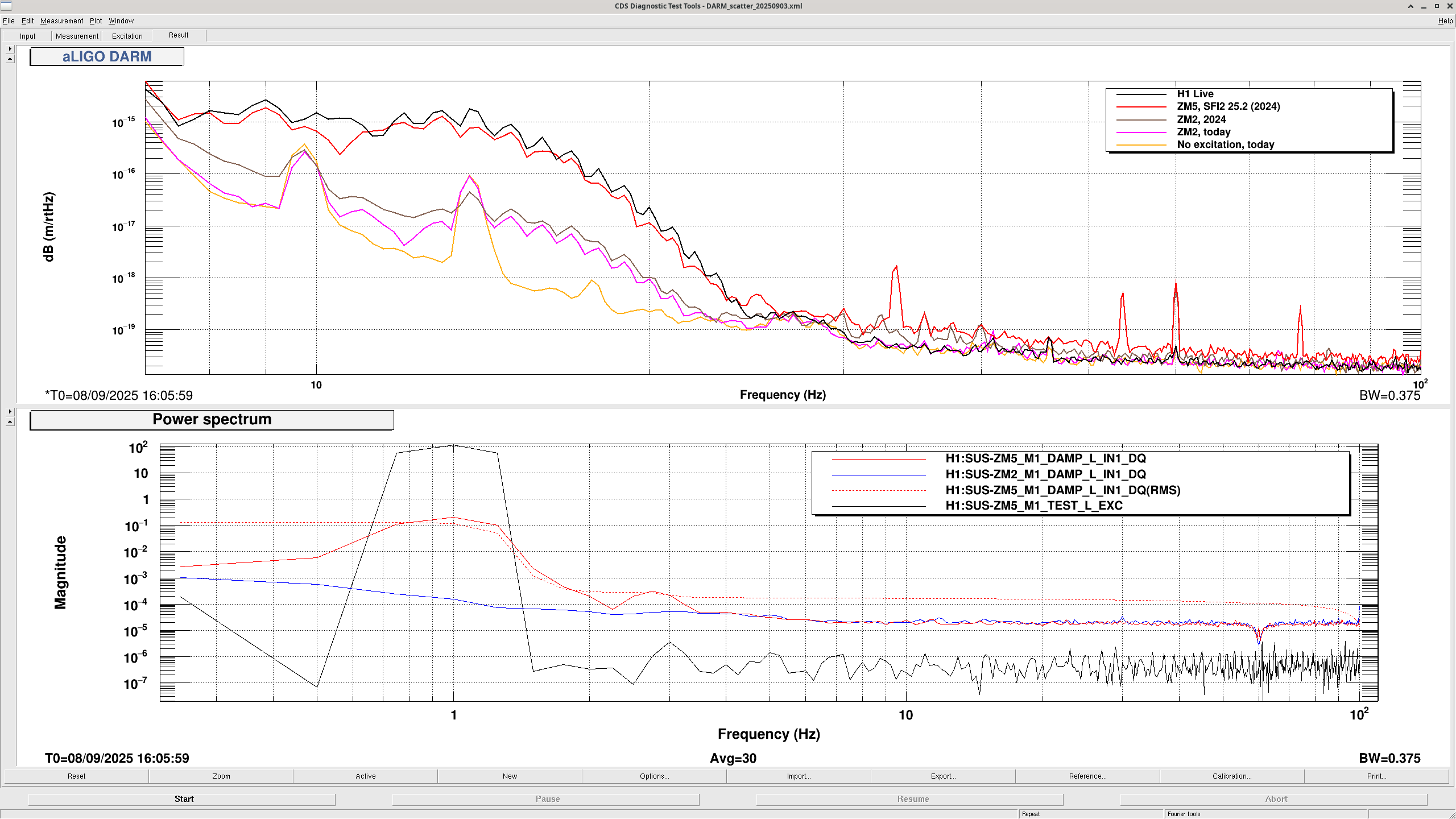
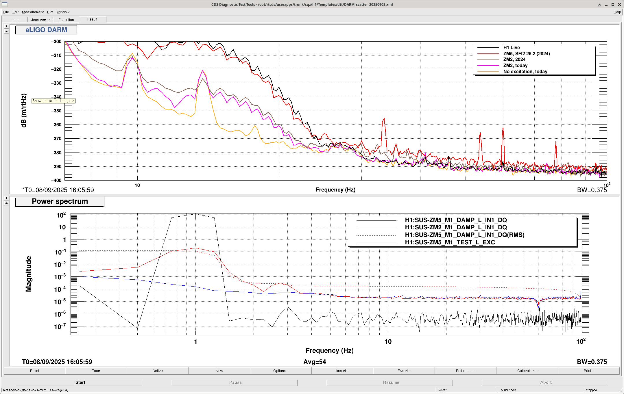
Fringe wrapping (scattered amplitude seems slightly lower than in 2024 when moving ZM2, slightly higher when moving ZM5):
- userapps/sqz/h1/Templates/dtt/DARM_scatter_2025_0903.xml
- quiet refs: 33-37
- ZM2 test L excitation 100 counts at 1 Hz, ref 38-40
- ZM5 test L excitation 100 counts at 1 Hz, ref 41-43
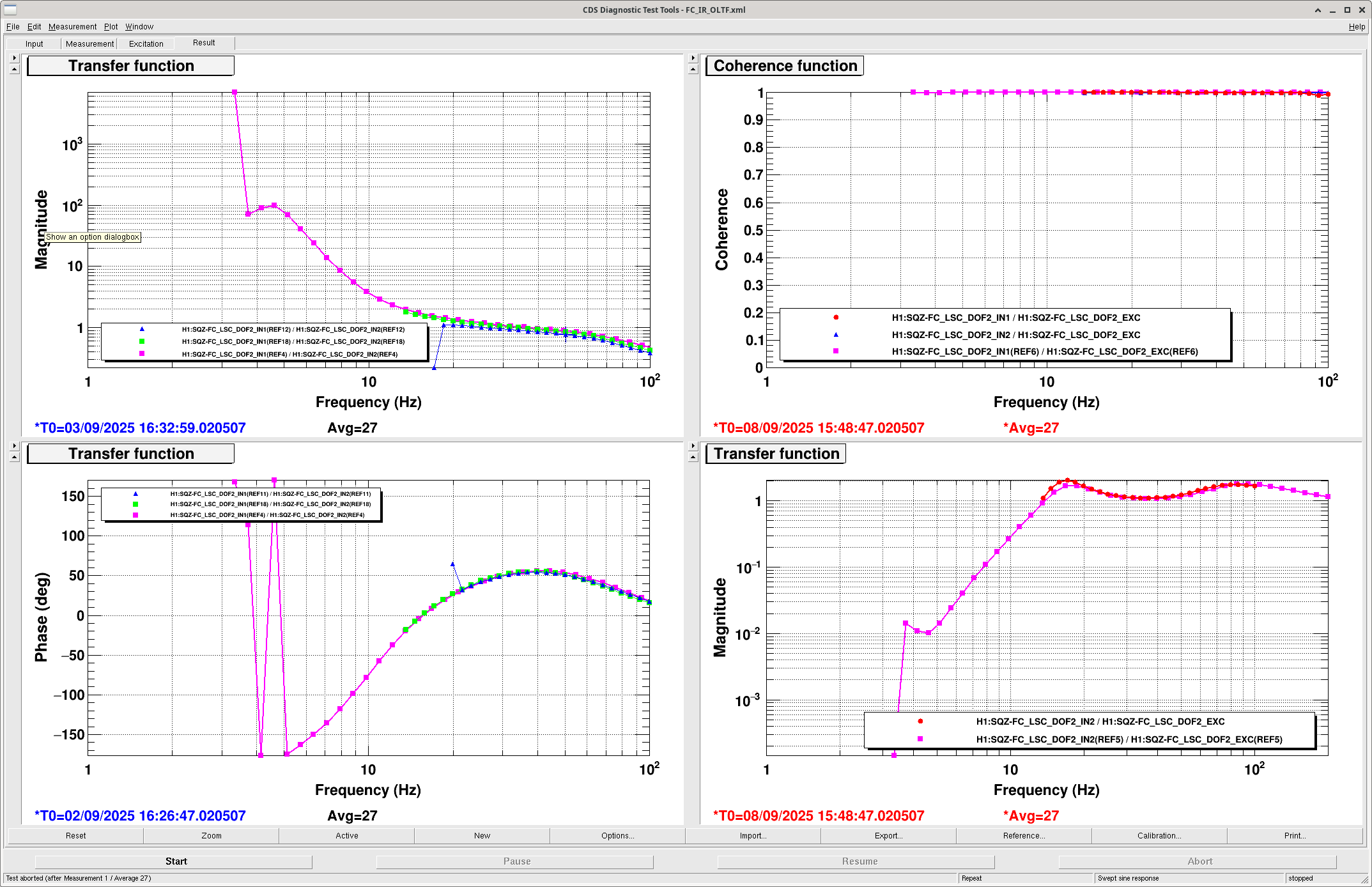
Open loop gain (also varies from day to day):
- ref 12 Sept 3rd
- ref 18 (8% higher gain than on the 3rd)
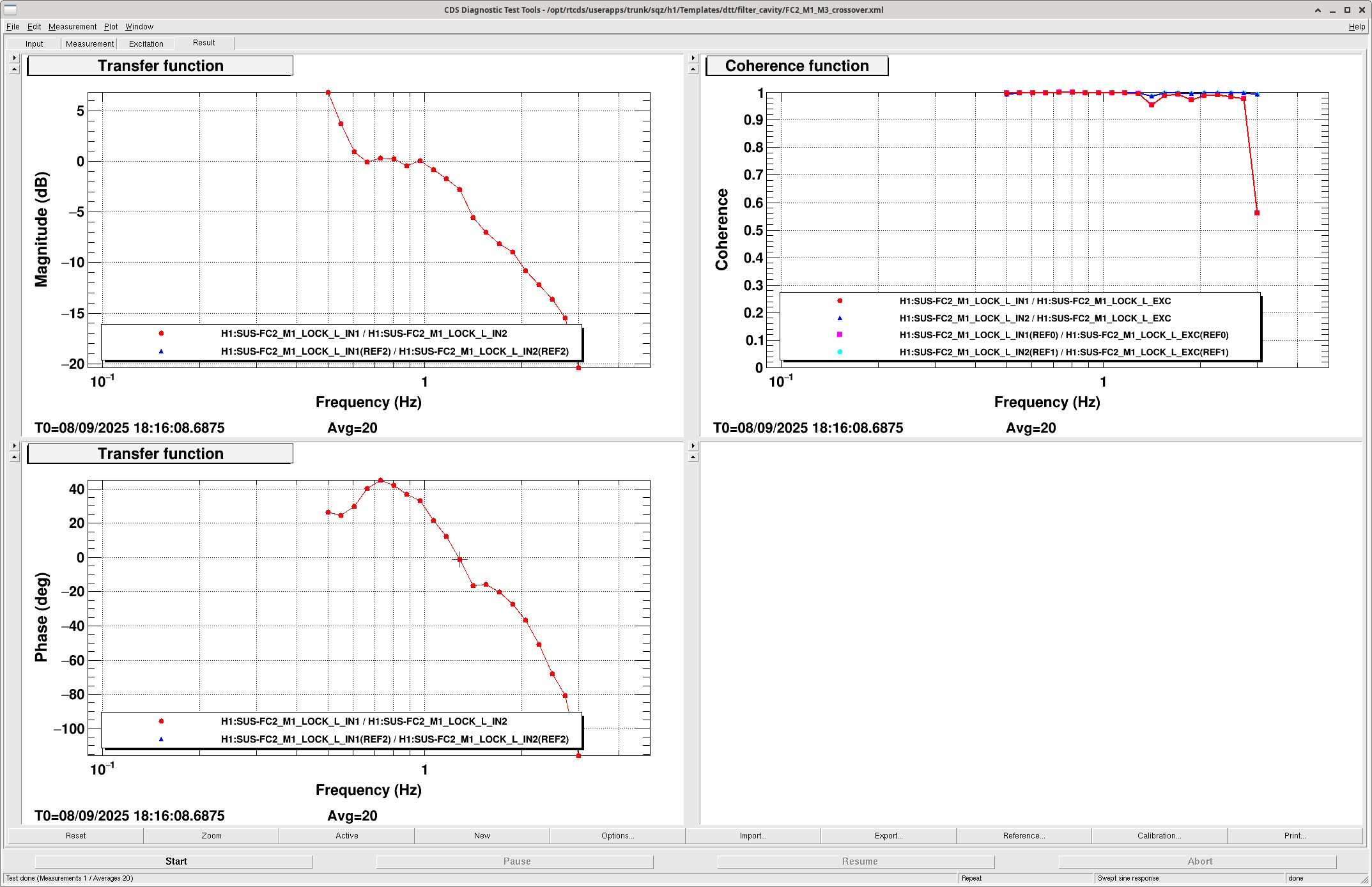
FC2 M1/M3 cross over:
- userapps/sqz/h1/Templates/dtt/filter_cavity/FC2_M1_M3_crossover.xml
- cross over looks to be 1 Hz, with an instability at 1.3 Hz and less than 3dB of gain margin
- while doing this I moved the location of a filter in FC2, which had to be accepted in SDF and updated in the guardian. This filter is set in the init state of the guardian, which should probably be moved to down instead of init. I also copied over a boost filter, but after doing the measurements it is clear we can't use that boost as is, so it is off.

Here's the plot of the fringe wrapping measurements in displacement units. It can be compared to a similar measurement made on ZM4 + 5 at LLO: 60856. Over email Peter asked some questions about the power levels needed to explain this.
Power level heading towards HAM7 from OFI:
The power on the DCPDs is 47mW, and there is 12pW retro-reflected off the filter cavity, so the total isolation provided by OFI + SFI2 + SFI1 is 2.5e-10 in power ratio, or 96dB. The OFI isolation ratio was measured to be 43dB in 79379. If this is true it would imply that one of the SFIs is providing less than the 30dB isolation assumed in T1800447, and we should have 2uW of carrier light headed towards SFI2.
Our readback of the 1% pick off of light from the interferometer heading towards SFI2, B:PD1 (OFI PD A) says that we have 0.03mW on it, meaning 3mW from the IFO going towards SFI2, about 1mW of this would be carrier based on (87114),which seems too high.
The responsivity of this PD was checked in 60284, and later double checked because it seemed low (the settings are still the same). The similar PD OFI PDB has a measured responsivity of 0.25A/W and the excelitas website lists a peak responsivity of 0.6A/W at 850nm for these PDs. (ffd-200h-si-pin) If we think that this calibration was mistaken and the real responsivity is more like OFI PD B, 0.25A/W, there is 0.72 mW of light from the OFI heading towards SFI2, ~240 uW of carrier, the OFI isolation would only be 23dB, and the SFIs must be providing something like 36 dB each.
Reflectivity:
If my interpretation of the fringe wrapping measurements into power are correct (12 nW of power is retroreflected from the path that includes ZM5), we are reflecting 50ppm of the carrier scattered toward HAM7 using the (recalibrated) 240uW value from OFI PDB, or 0.6% if we believe the isolation ratio measurement for the OFI and use the 2uW value. B:BS1 is a 1%, so the maximum reflectivitiy we could get from scatter in the B:PD1 path would be 0.01%. This means that the B:PD1 path can't explain the reflectivity needed if there is 2uW headed towards HAM7, and even if there is 240uW heading towards HAM7 this PD seems unlikely to explain the scatter, since it would need to reflect half the light that's incident on the PD. Camilla did alog the check of the alignment (and the beam dump catching the retro-reflection off this diode: 65006)