
REMOVE SEARCH FILTER
SEARCH AGAIN
Search criteria
Section: H1
Task: TCS
Mitch, Camilla, WP#13559
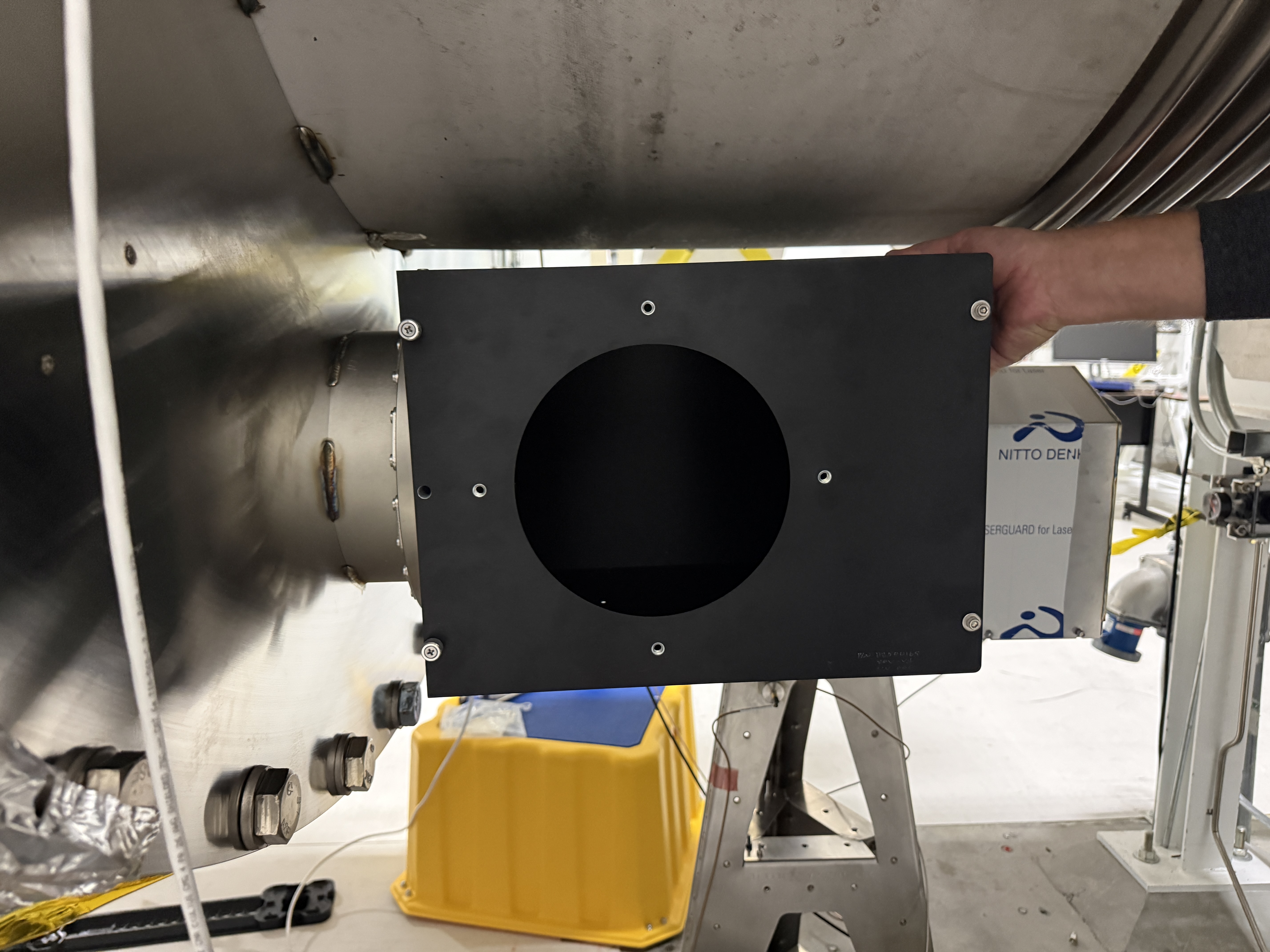
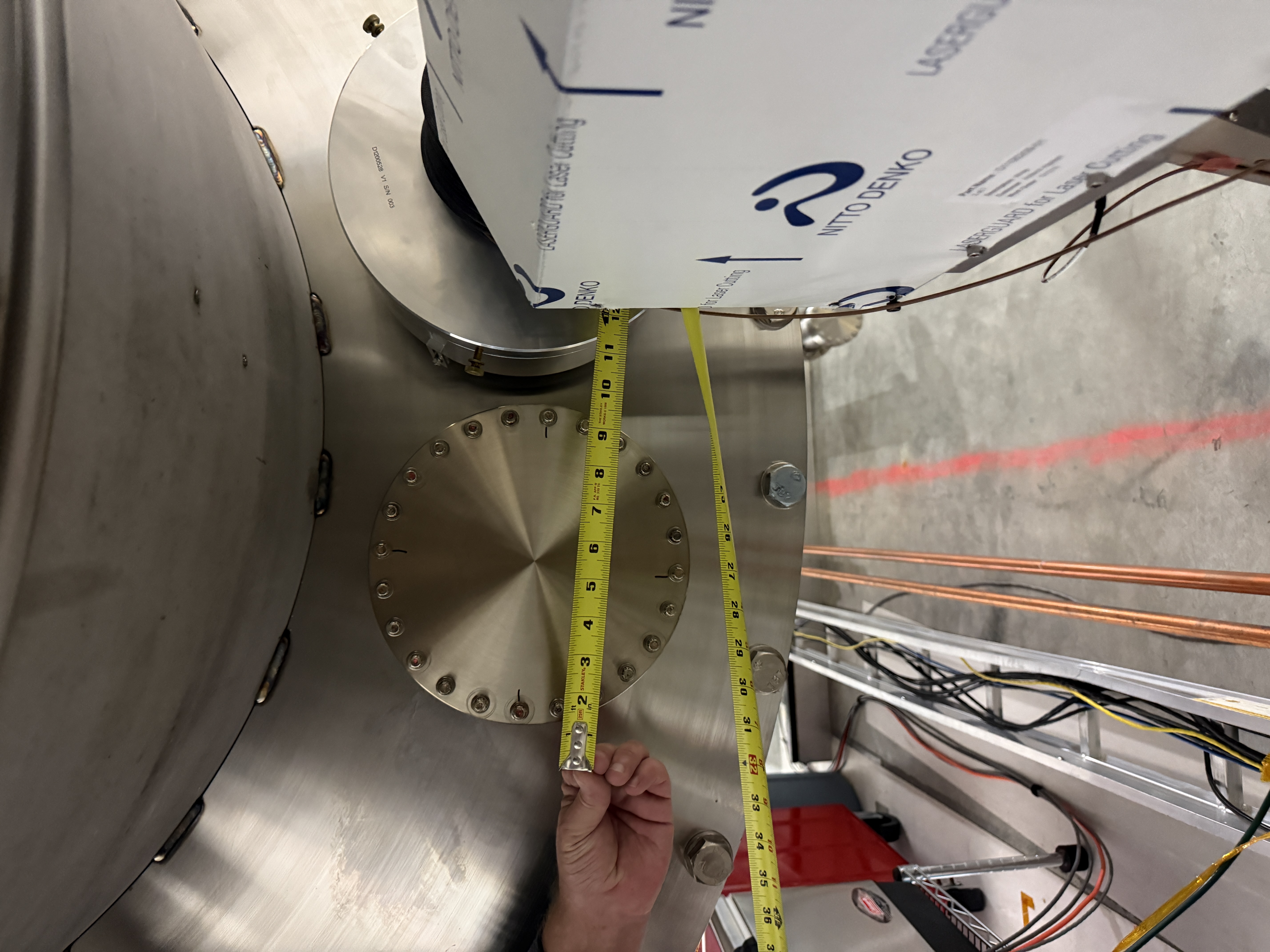
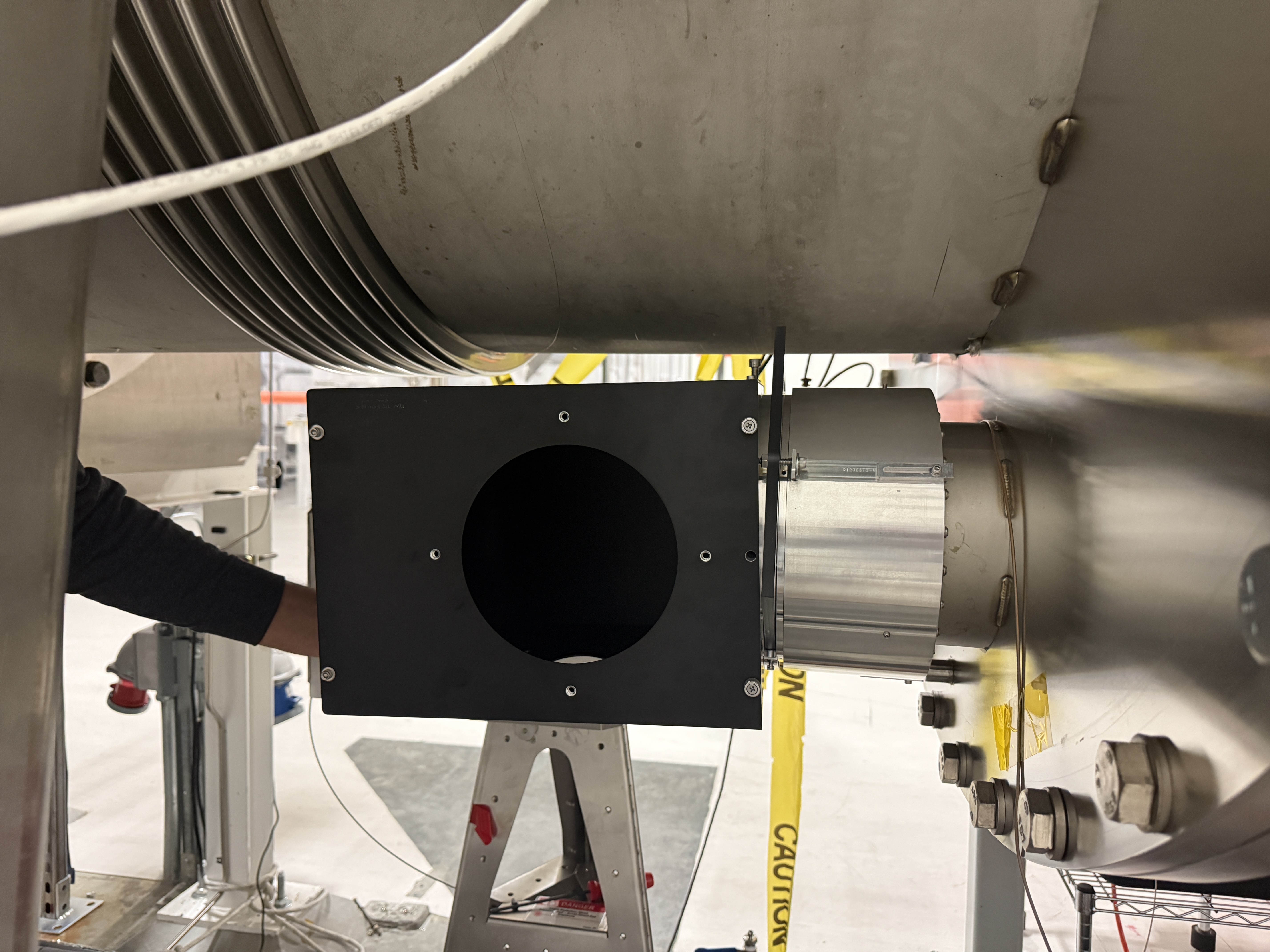
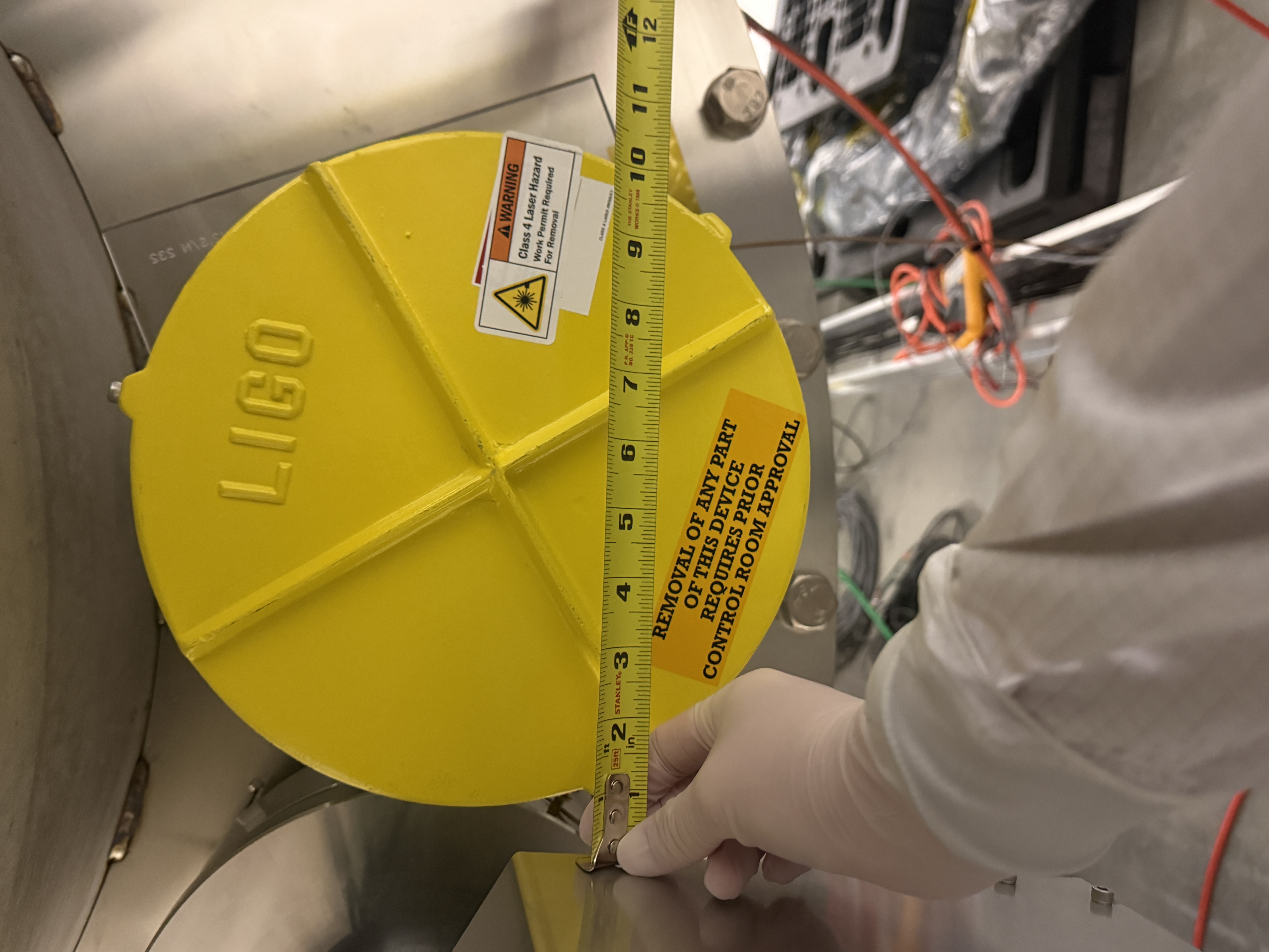
Tyler modified the D2500166 as it was too wide to sit next to the Oplev laser enclosure. Tyler modified: D1300702 and D1300703 so that the box is now ~0.75" offset of the center. Will add more deatils to these modifications in the DCC.
At the X-arm adapter plate this technically fits but is close to interfering with the op-lev laser enclosure. The 10-32 bolt next to it will want to be replaced with a button or countersunk bolt. Photos attached: side view, below view, ruler.
At the Y-arm adapter plate this fits well. Photo attached: side view, below view, ruler.


FAMIS (no number atm)
This morning I inspected the lines starting from the chillers and then went to each table. Everything looked good: no leaks, stress on pipes, etc.
I did have a scare when I saw liquid pooling around the Leak Detection Dixie Cup (LDDC) on the mech room mezzanine. Turns out it was glycol from the HEPI lines and it just happened to land next to the LDDC after dripping down an extention cord, dripping down two pipes and finally resting next to the cup. Jim was notified, picture sent.
FAMIS81869
With our FAMIS tasks up and running again I was reminded to swap out the chiller sock filters. The old filters both were slightly discolored, but there were no large bits of debris or other worrying particulate. I also replaced the X chiller radiator screen cover as it had a few dead bugs in it and hair.
I did not add any water as it was at a good levels for both chillers. I've updated T2200289.
Followed instructions in 68391 with 2 minute 2W CO2 blasts. Last done in 80834. Starting location with pico H1:SYS-MOTION_C_PICO_G_CURRENT_X,Y_POSITION at (0,0) starting hws plot attached. Aim to center on ITMY, center marked by origin cross using RH in 91567 went to that O4 SR3 alignment for this test. Endign picos are at (2000,0), ending hws plot attached.
Reverted SR3 to new location.
Once we know location of IFO beam, we should touch this up again.
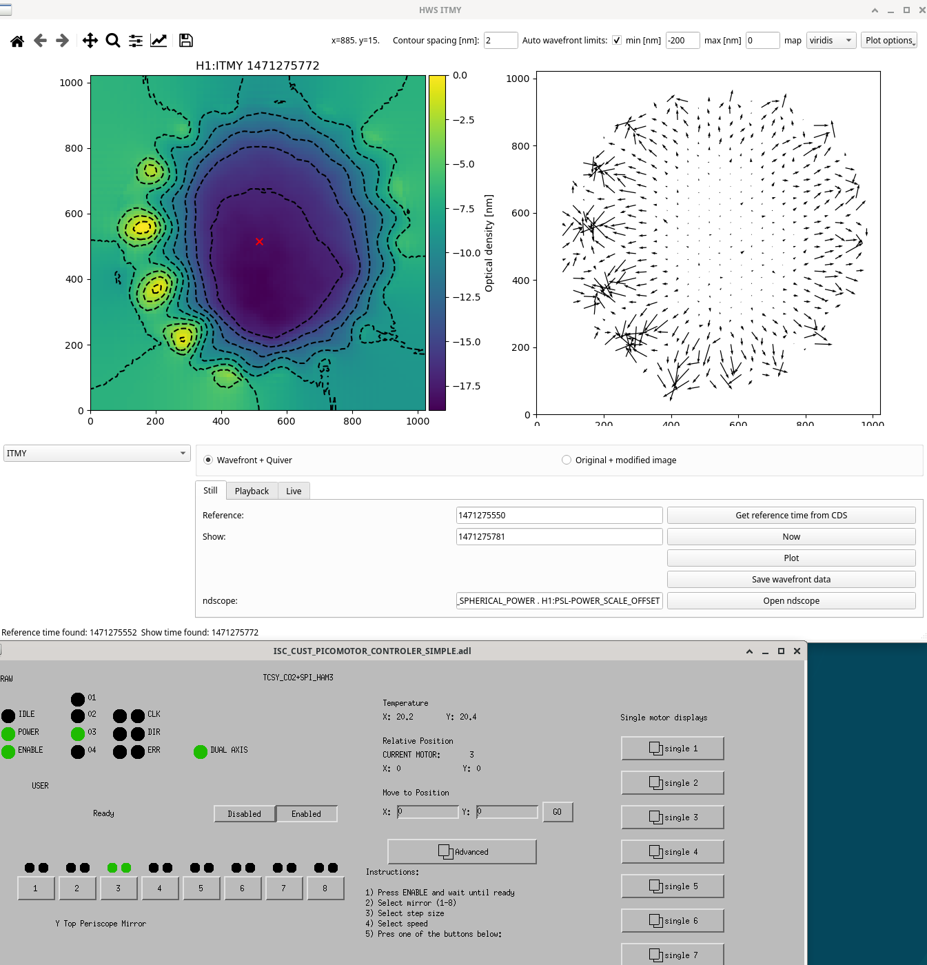
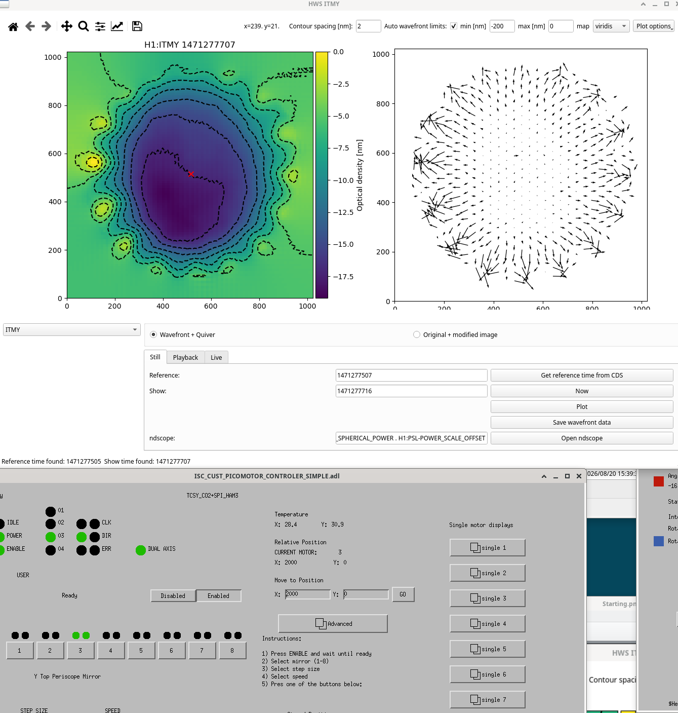
TJ, Fil, Camilla
We turned on CO2X laser without issues. TJ had to turn on Outputs of power supplies on the mezzanine. We searched for home of the rotation stage and checked that the beam was aligned to both irises before the periscope. Leaving laser on at minimum power. Guardian did successfully lock laser.
For CO2Y, we were unable to turn it on. We checked SMA connections on laser head, BNC and TNC connections between RF driver and laser and tried turning on in PWM mode with the PWM driver. Fil then swapped chassis D1700745 to a spare. This did not help. TJ then swapped the RF cables t the TCS-X rack for X and Y. X laser stayed working, Y laser still not working. Fil checked the AA chassis. Fil and TJ looked at swapping the power supplies at the mezzanine but this was complicated and the power supply appeared to be behaving normally.
This afternoon we swapped the chassis back. We then swapped the small square-wave RF box to the spare. And then swapped the RF driver briefly to the spare, this is not matched and we did attach cooling lines but had on for ~30seconds. Neither of these things helped so we swapped back to originals. We then noticed that the rocker switch was off on the D1300649 chassis inside the CO2Y enclosure. Turned this on and everything was fine.
CO2 Y laser turned on fine. We searched for home of the rotation stage with downstream beam dump and checked that the beam was aligned to the upstream iris before the periscope (we bumped the downstream iris while changing cooling lines). Leaving laser on at minimum power. Guardian did successfully lock laser.
TJ, Camilla
I put SR3 into it's O4 alignment (P 458, Y -135) changed from (P 524, Y -135), checked no saturating pixels (ITMX stayed at 1Hz frame rate, ITMY increased to 5Hz), took new HWS references and started the HWS code.
We are running a ring heater test with 2W/segment for 4 hours this evening. Using scripts below on tmux sessions:
Ring heaters should be back to nominal by ~1am. Purpose of this is to check HWS alignment before we align the CO2s (using HWS).
TJ, Camilla ITMY HWS signal looks great. ITMX HWS signal looks noisy, the power on the CCD camera is much smaller than expected, expect this needs realigning after the BS is different.
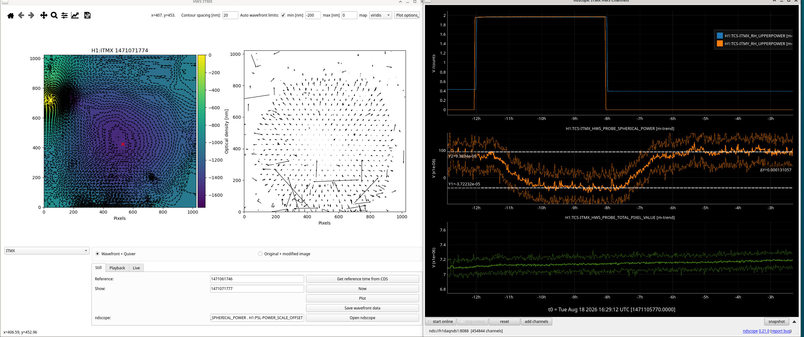
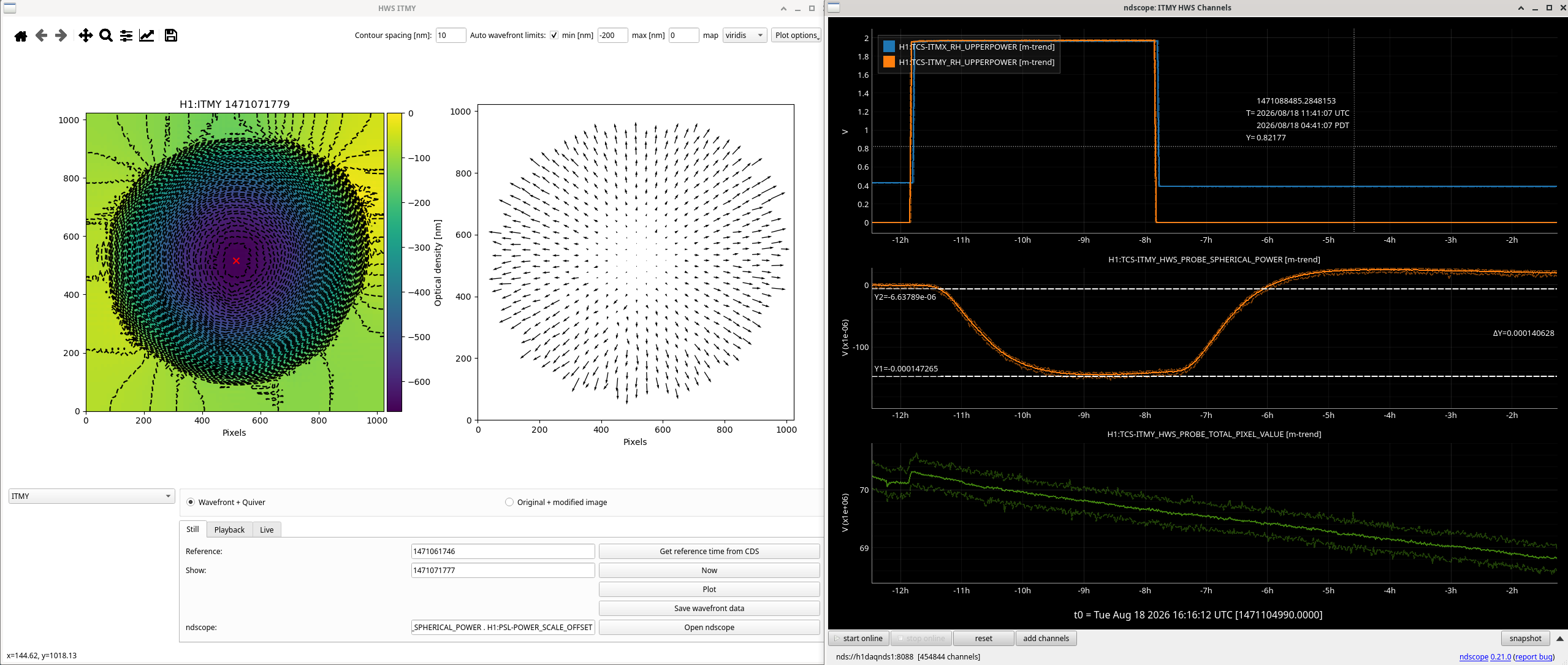
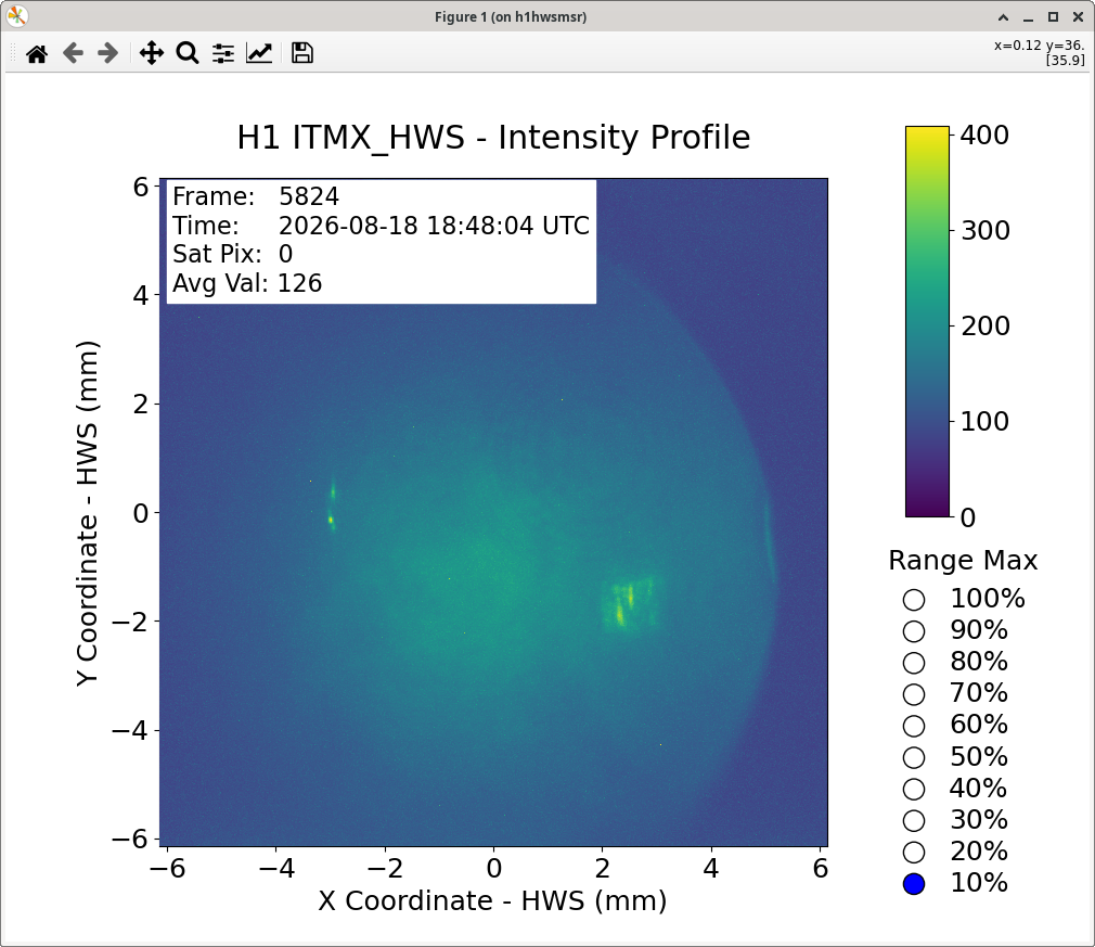

TJ, Camilla WP #13528
Today we swapped the ITMY HWS SLED as it had degraded, last swapped May 2025 84417.
Following the T1500193 procedure
Addressed TCS Chillers (Wed [aug5] 1213-1225pm local time) & CLOSED FAMIS #81868.
For measurements below, measuring from "top" of the red floaty ball.
Took ZM4,5,6 to SAFE.
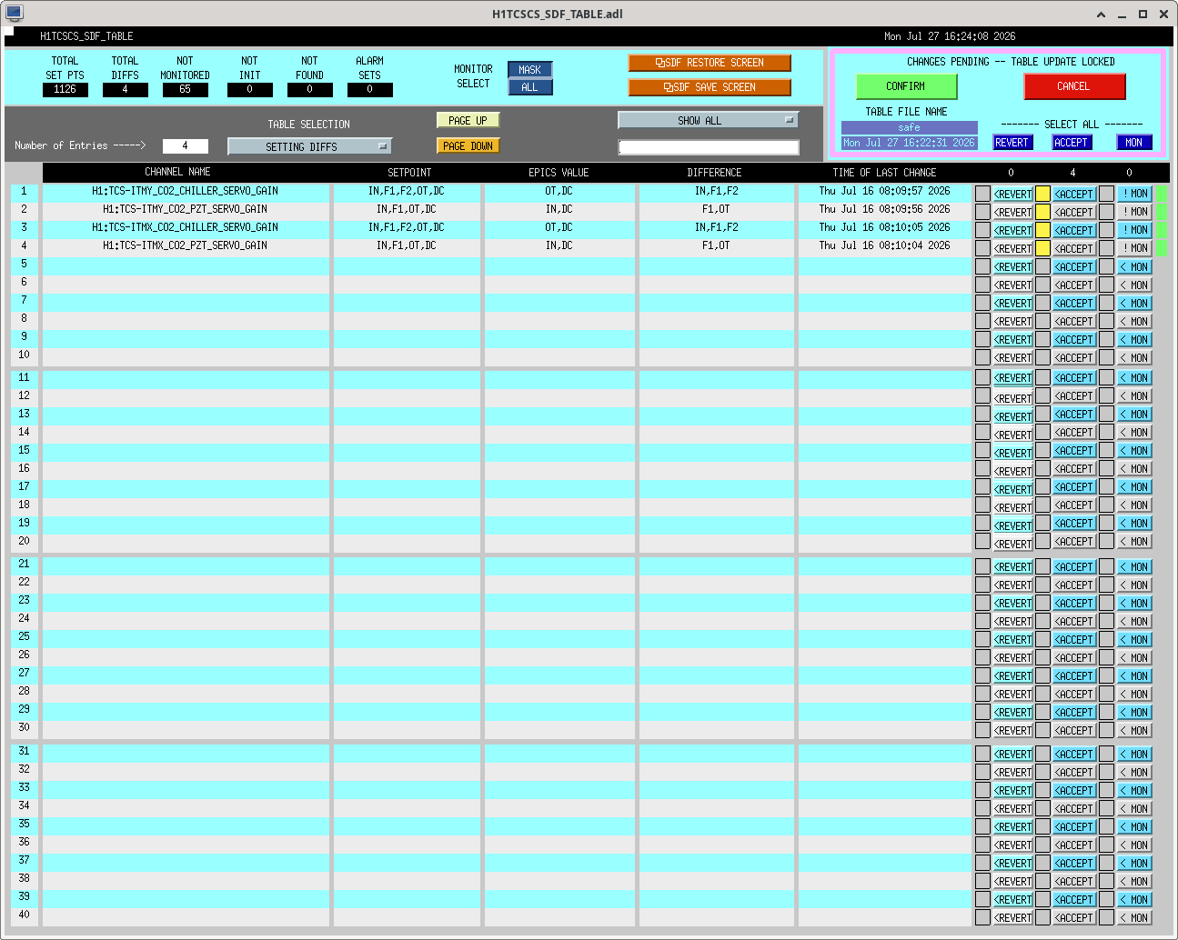
Accepted some TCS HWS settings, turned the EY enclosure lights off via medm (already off on table) , unmonitored the CHETA flipper. Attached.
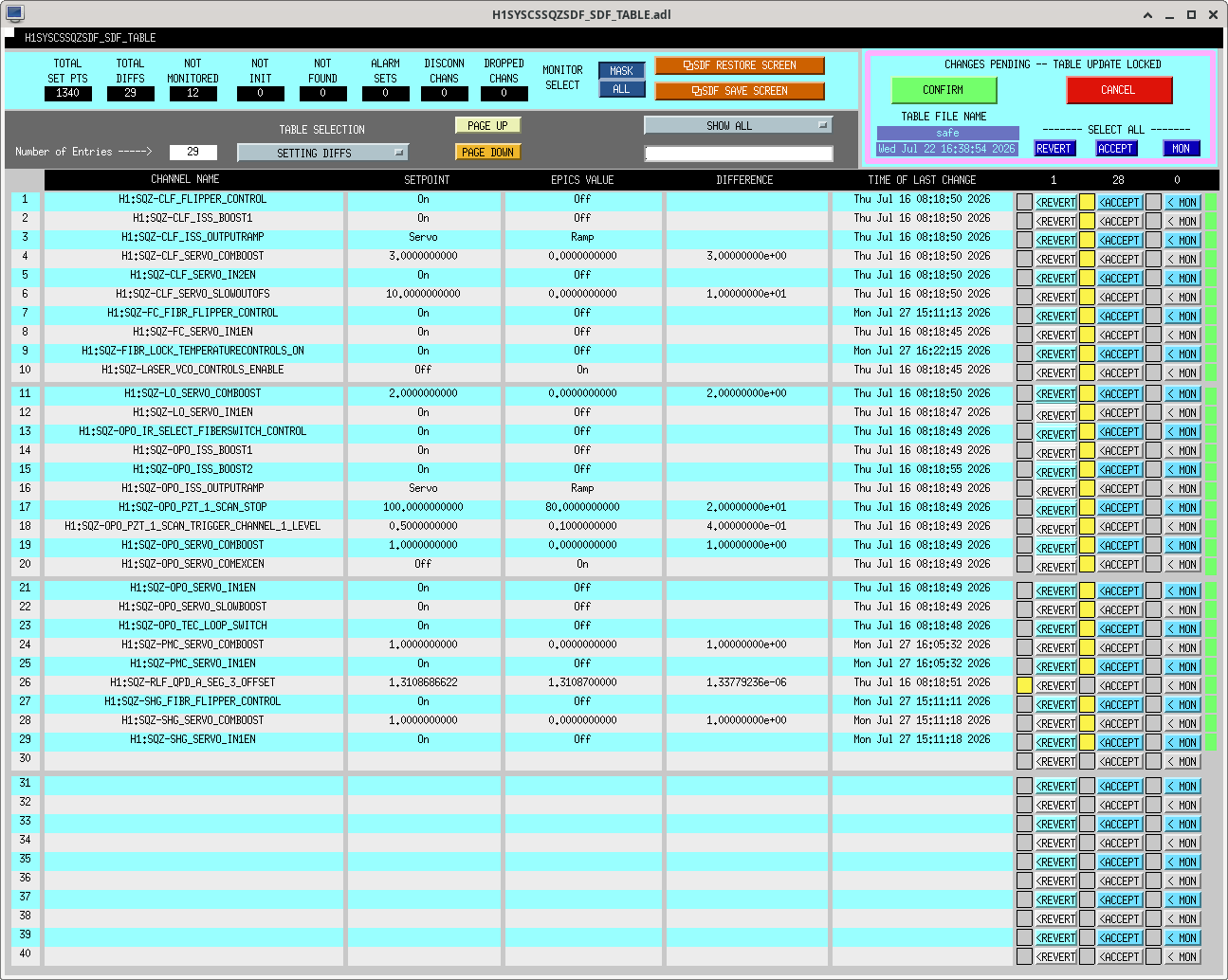
Stil have more SQZ and CO2 to do....
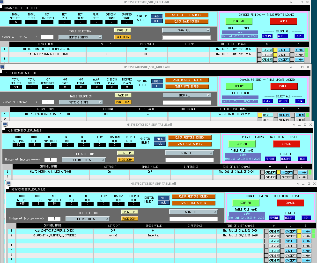
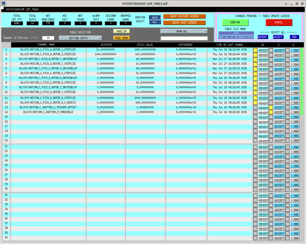
CS_AUX Disabled then reverted picomotor settings, attached. Accepted ISCT6 AS Beam shutter (SHUTTER_M_THRESHOLD) from 1.2V to 2V as it's been this since ~February. Fast shutter (SHUTTER_G) offset accepted.
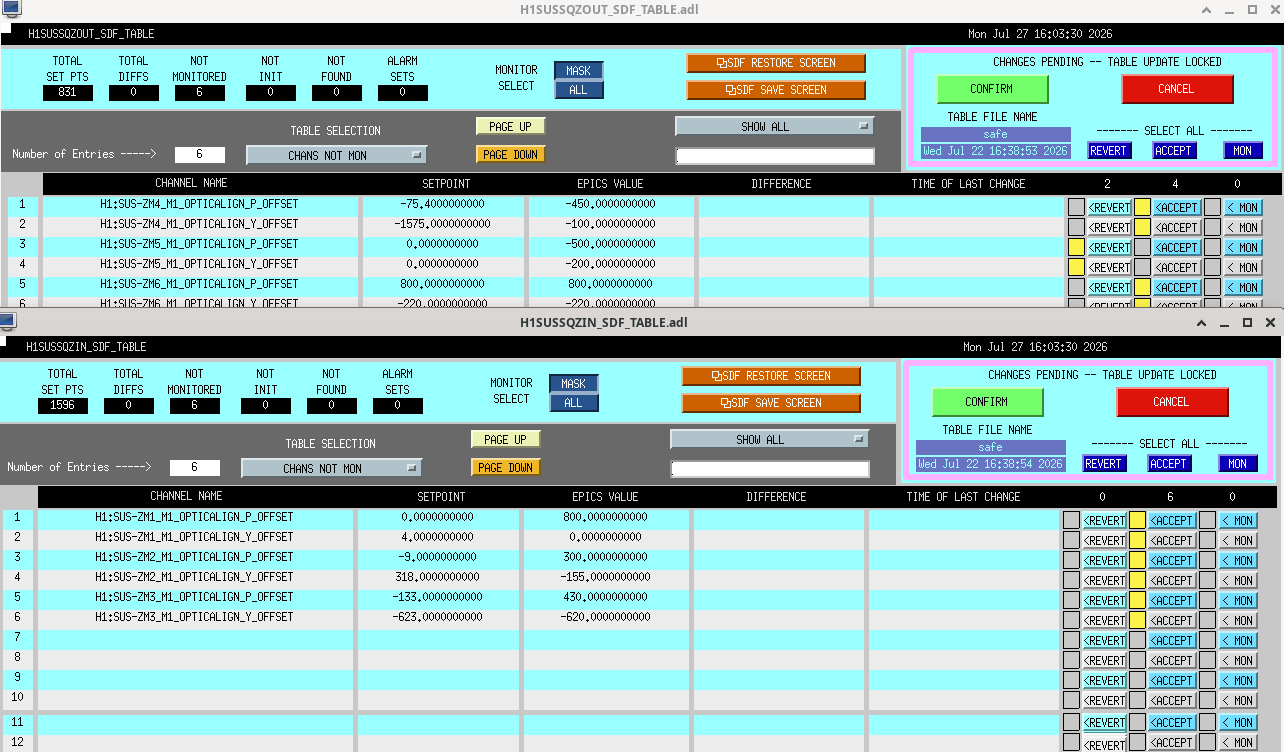
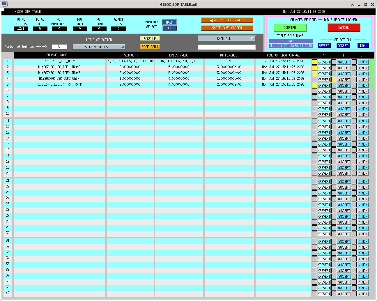

Madi, TJ
This week, TJ and I went down to EX to re-measure the location of all components within the EX HWS path. The updated measurements are in the attached file.
We each measured the distances, to give some indication of the uncertainty on each measurement.
Addressed TCS Chillers (Tues [Jul21] 919-934am local time) & CLOSED FAMIS #64385.
For measurements below, measuring from "top" of the red floaty ball.
M. Todd, C. Compton, T. Shaffer
We had a go today at pointing the FLIR Boson+ camera at ITMY with the ring heaters on at 2W per segment. In short, we were not able to see anything with the FLIR Boson+ yet. My feeling is that the camera should definitely be able to see it, as we pointed another hand-held FLIR and were able to see a bright spot where we though the test mass was (though it was pretty out of focus because the hand-held is not as great as the Boson+). The issue with the current setup is the camera pointing is not easily adjusted, and did sit centered in the camera can that we were able to fit on the viewport.
The setup with the guillotine was to take the back off of a camera can and mount the camera in there as best we could without anylenses to maximize our field of view. Then we attached the camera can and removed the guillotine to look at the ITM. We tried removing the background because the image seemed completely saturated as if it was catching a reflection from something. We tried adjusting the aperture to reduce this but had no luck. We tried removing the camera can and pointing the handheld FLIR at the ITM and saw a bright spot that looked like it could be the ITM, so we tried again with the camera can slightly rotated to see if the seating in the camera can was an issue --- again without any luck.
Overall, I think it deserves another test using a pitch-yaw mount or something and a little bit smaller footprint so that it fits in the camera can more easily. Additionally, we should see what the lenses are for the other cameras used pointing at the ITMs, as they will probably be useful.
I also found a Windows GUI that interfaces with the camera a little more customizably, which may be useful for future tests as well.

ITMY has been turned back off to 0W /segment, this is nominal.
Matt, TJ, Camilla
Today we did proof of principle measurements of the CHETA beam size using the FLIR camera.
In 13940 the CO2 beam was projected onto black construction paper in the LVEA. Today we projected the CHETA beam (at low power, <100mW) onto the laser curtains in the CHETA lab. We measured it using a ruler with paper markings taped on at 2" increments, it was easier to see the ruler once it was warmed up by our hands.
We also moved the QPD 2" lens 200mm FL into the path 230mm after M4 and 500mm from M4, for both of these, the beam appeared to be ~1" in diameter. The laser curtain was 67" from M4. Photo attached.

Matt, Camilla
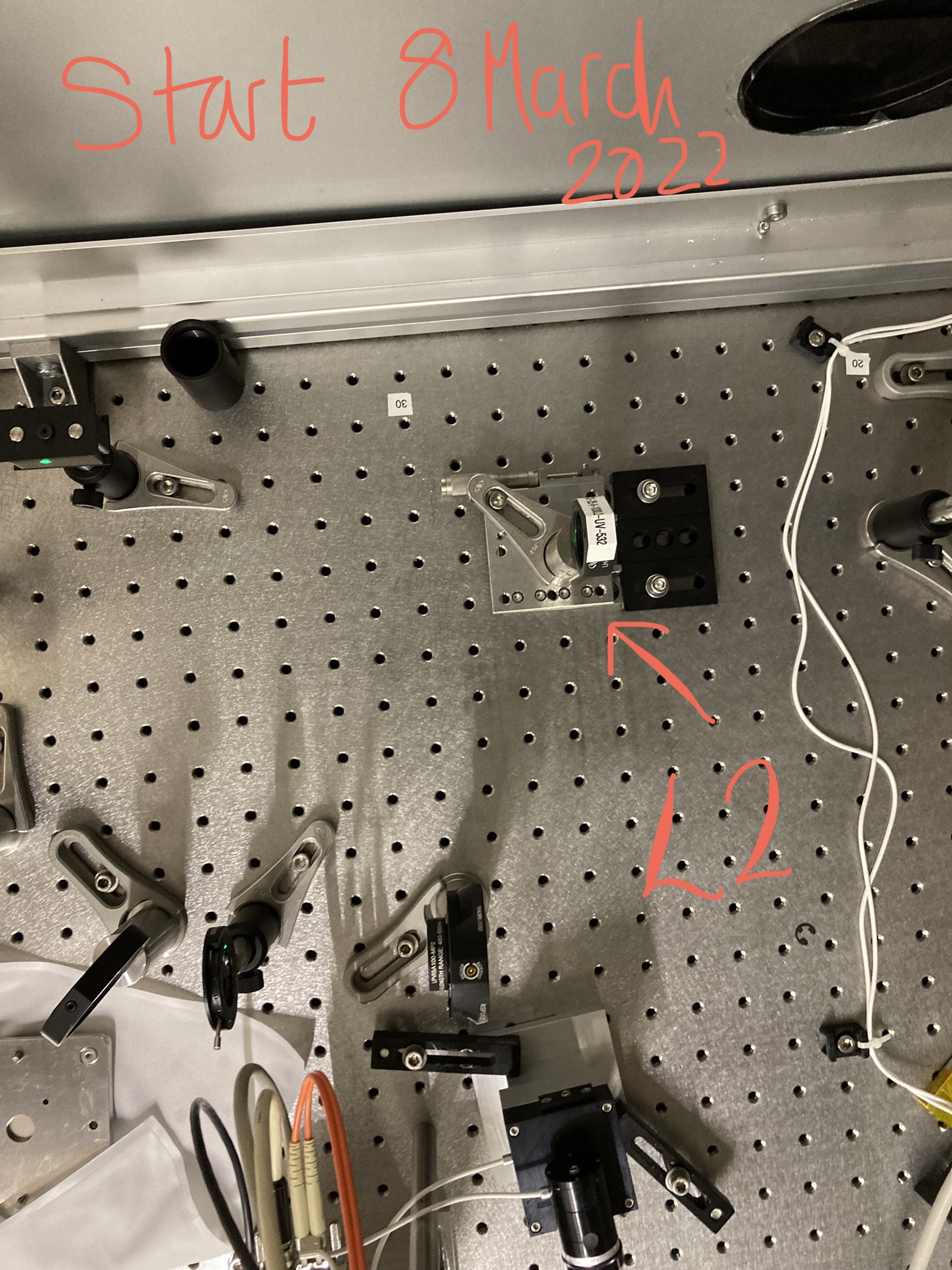
On July 9th, we used the Ophir Nanoscan to take data on the CHETA Y-arm Table Laser 0918 with L2 at different locations on the translation stage. Data is attached to D2500319.
We then used Fintrace to project this to the ITM. Data must be saved with correct file name for this analyzer to work, using logger function of Nanoscan V2 to save. Used command: python beam_profile_analyzer_nonlinear.py /DATA/20260709_0918_after_L2_m10/ --z-offset 245
|
L2 Translation Stage
Offset
|
Fitted q propagated to ITM
|
% Astigmatism
(Beam size)
|
|
|
Horizontal
|
Vertical
|
||
|
-35mm
|
46.65 mm
|
48.73 mm
|
4.4%
|
|
-10mm (Nominal)
|
53.06 mm
|
51.03 mm
|
3.9%
|
|
+15mm
|
62.17 mm
|
57.87 mm
|
7.4%
|
At the nominal beam size of ~53mm on the ITMY, the beam size astigmatism is 3.9% which we think is acceptable.
We also took some data with the analyzer at a fixed position while moving L2 along the translation stage, this is also attached to D2500319.
Vicky, Austin, Camilla. Follows yesterdays alog 62089. Summary: aligned but weren't able to see any baffles and beam is smaller than ideal.
Austin and I measured distances between optics (all measurements attached and key ones below):
| INCHES | mm | |
| L3 to L2 | 41 | 1041 |
| L2 to L1 | 21 | 533 |
| L1 to LPM | 60 | 1524 |
| HWS to L3 | 58 | 1473 |
We started with translation stages at: Collimating lens @ 1.44; HWS:L2 @ 12.39. Later Vicky and I moved the L2 on it's translation stage upstream ~ 1.5" (starting location attached).
Vicky and I realigned the beam to remove the majority of the ITM reflection. Once we were finished and ETM was misaligned we could still see faint rings reflected off ITMX (that moved when ITMX adjusted) photo here. So more alignment could be done to get rid of those. We adjusted the CCD camera to try nd focus better but didn't see a difference so replaced in original position.
We adjusted the collimating lens and L2 to try and get the retro-reflected beam at the iris after ALS-M11 D1800270 to be a similar size as the outgoing beam - it is ~ double the size which is the best we could get with the 40mm collimating lens. The waist of the beam is still just after L3.
Adjusted wave plate to maximize beam to LPM from 270 to 292. This might have been the cause of reflected beam streaks we see on the camera. In the final image.
Final beam after yesterday is attached. It still seems to small to me so maybe we need to go back to the 50mm lens. Once we are happy we need to dither the ETM to measure the magnification.
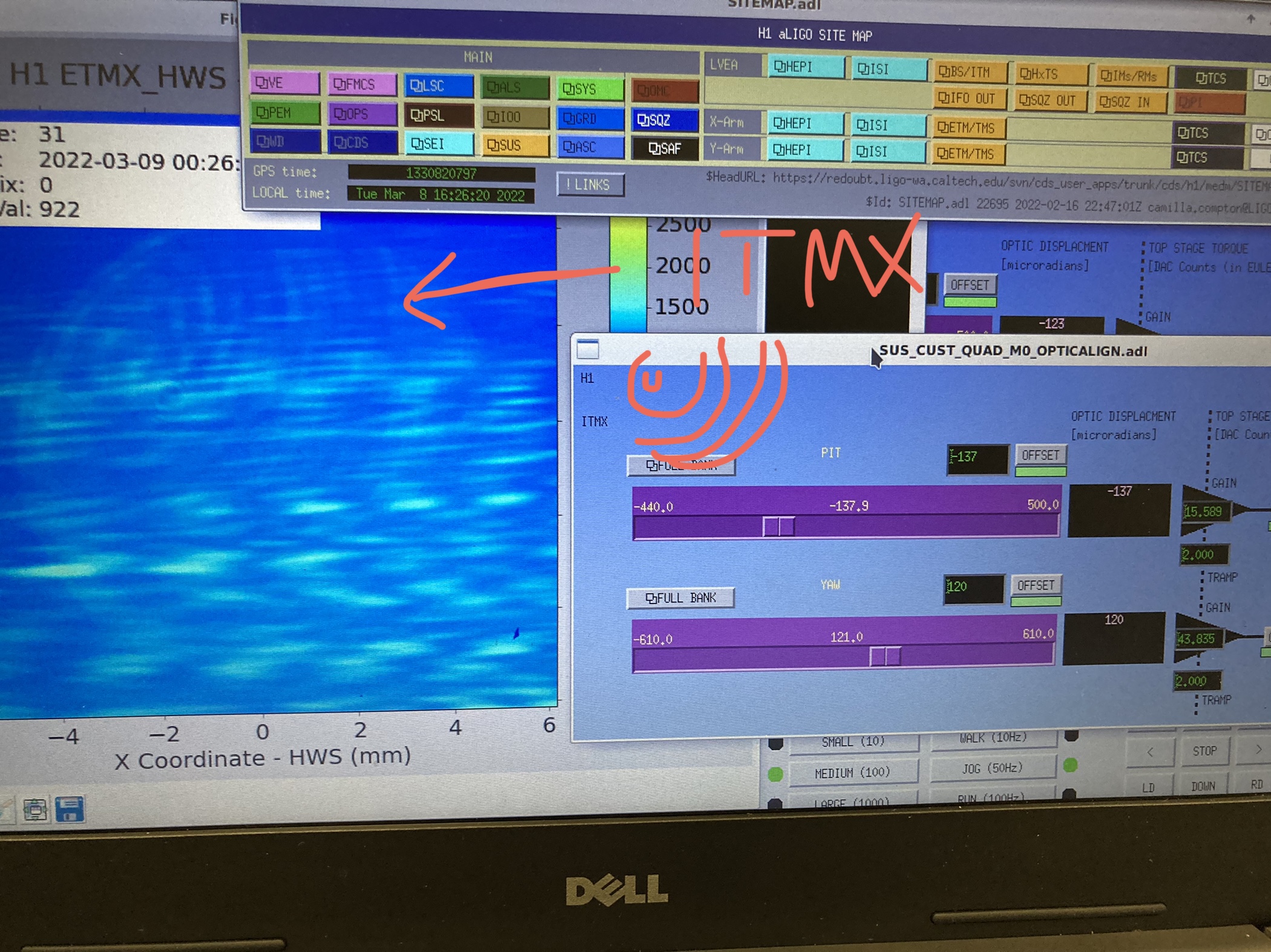
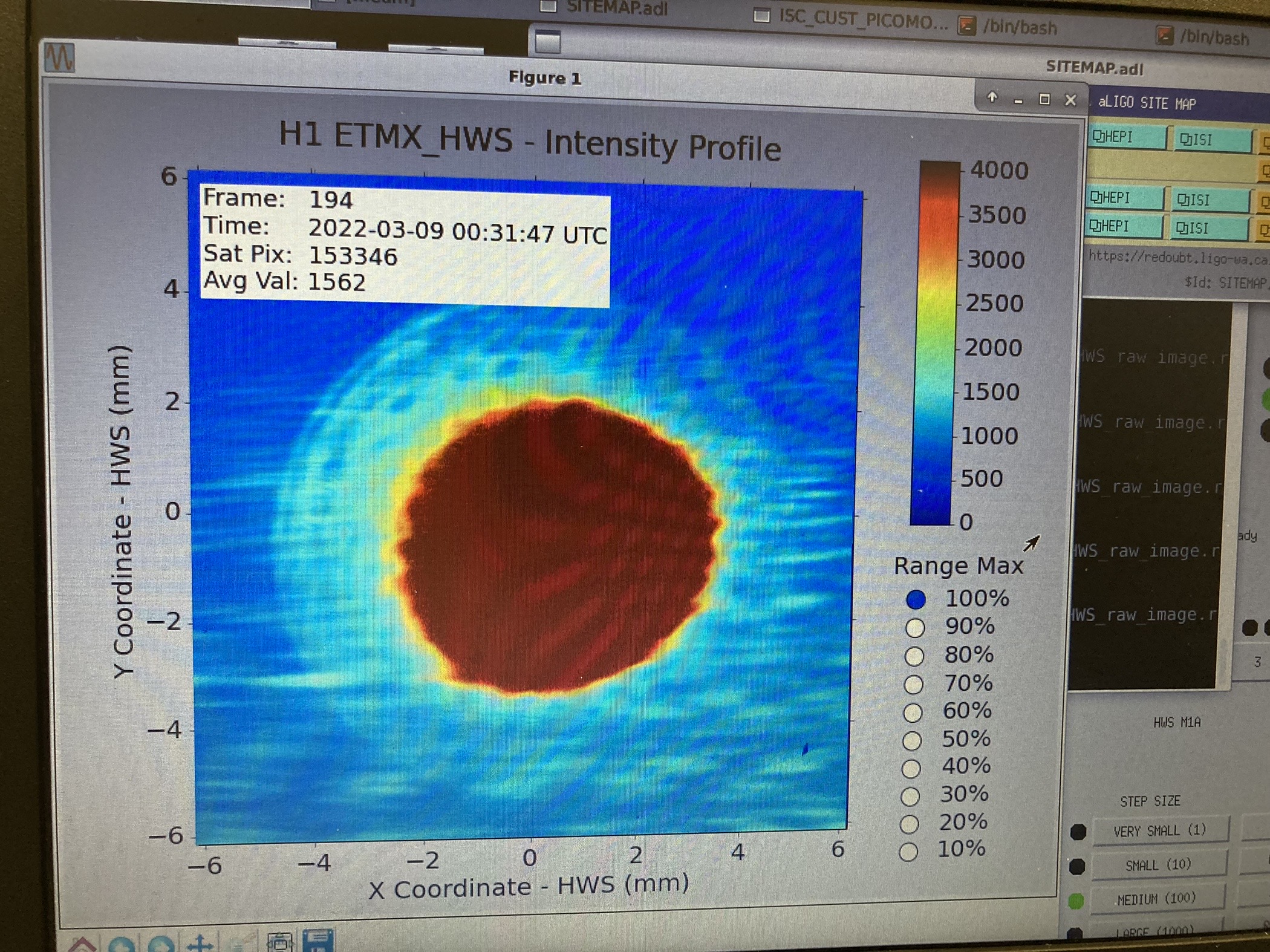
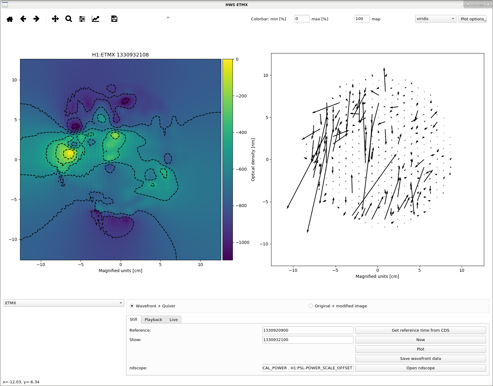
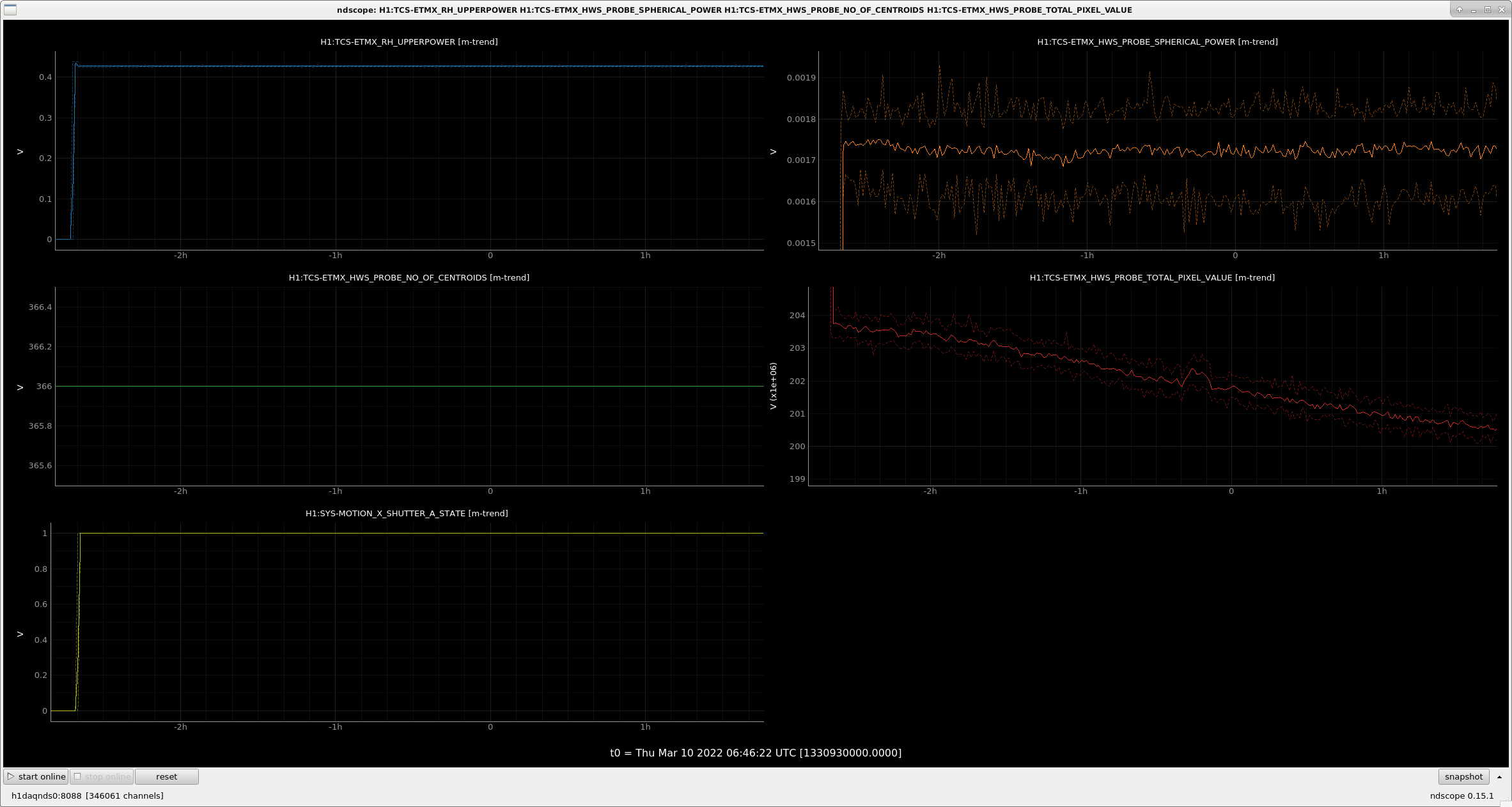
From a controls tmux session on zotws24 I'm running a ETMX 0.5W ring heater test 2am-4am. Script will close ALS EX, EY shutters at the start. >> python3 /opt/rtcds/userapps/release/tcs/common/scripts/power_adj_scripts/ring_heater_schedule_shutterALS.py ETMX -s 1330941618 -d 2 -p 0.5" Robert will shutter ALS and when he turns the ring heaters back to thier nominal O3 values tonight.
This morning I replaced the Hartmann plate but didn't track down the source of the scattered light shown in alog 62121 photo yet.
The baffle is a 190mm circular aperture that should appear around 9.3mm in diameter on the HWS camera (assuming magnification of ~20.5X) - see aLOG 60937.
The aperture that appears in the HWS images looks plausible as the baffle shadow.
The ring heater test doesn't look like it's showing us anything much see attached. The spherical power is noisy and doesn't show any change. The TOTAL_PIXEL_VALUE does decrease.
Madi, TJ
These on-table distances were re-measured 22nd July 2026, and posted 91241
