Keita, Rahul
We received three mirrors (JM1, 2 and 3) for the Jitter Attenuation Cavity (JAC) from CIT and were asked to characterize these mirrors before installing them in HAM1 chamber for the upcoming vent at LHO. JM1 and JM3 optics will be used in Tip Tilt supension and JM2 optic will be on a fixed mount inside the HAM1 chamber. Given below are the details of our setup and the results after characterizing them in the optics lab.
Aim of the experiment:- (a) to measure the reflectivity of the three mirrors as a function of its Angle Of Incidence (AOI) for P polarization of the input beam (1064nm laser), (b) measure the transmission of the optics at its AOI (defined in T2400360).
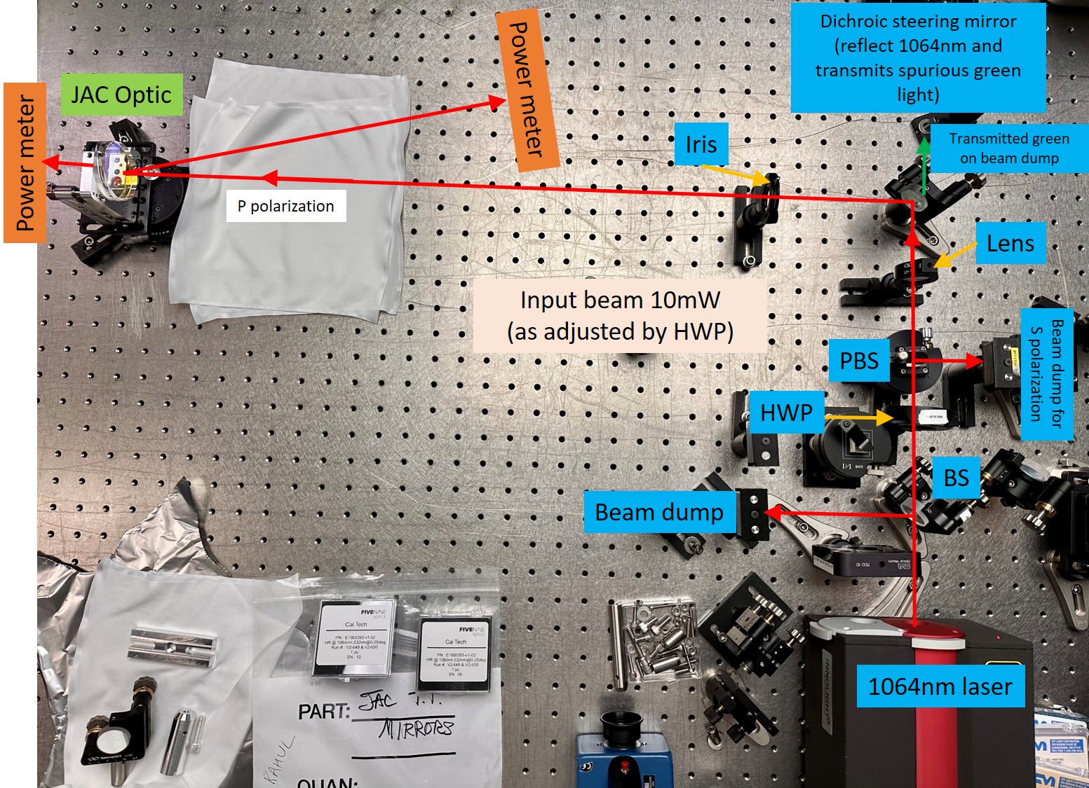
Experimental setup in Optics lab:- The optical layout is shown in figure1. We used a 1W 1064 nm laser (the power was reduced to 15mW approximately using a half wave plate). A polarizing beamsplitter was used to transmit P polarization waves to the steering mirror and the S polarization waves were reflected towards beam dump. The steering mirror used over here is dichroic (reflecting 1064nm light and transmitting/rejecting spurious green light emerging from the laser towards the beam dump). We used two lens to focus the input beam - one located upstream of the steering mirror and another one downstream of the same. The optic was installed on a Siskiyou mount, which was placed on a rotational stage - as shown in the picture. Thorlabs Power meter was used to measure the input, output and transmitted beam.
Results:-
We did coarse and fine measurement to characterize the mirrors. For coarse measurement, we started at zero degree AOI (when the input beam was reflected back towards the iris) and then rotated the optic until the output power nulled - while recording the reflected power at every 5 degree interval.
| Optic | Input beam power (mW) | AOI from T2400360 (degree) | Measured AOI for 99% reflectivity (degree) | Notes |
| JM 3 - E1900393_V1_02 s/n 09 | 15 | 5.07 | zero to 35 degrees | reflected power dropped to less than 5mW at and above 40 degree AOI (null at 50deg) |
| JM 2- E1900393_V1_02 s/n 10 | 15 | 9.77 | zero to 35 degree | reflected power dropped to less than 5mW at and above 40 degree AOI (null at 50 deg) |
| JM1 - E1900393_V1_02 s/n 16 | 15 | 45 | zero to 65 degrees | reflected power dropped to less than 3mW at and above 70 degree AOI |
For fine measurements we set each optic at its AOI (as defined in T2400360) and then carefully measured the input, output and transmitted power. The results are given below,
| Optic | AOI degree | Power, Input beam | Power, reflected beam | Power, transmitted beam |
| JM 3 - E1900393_V1_02 s/n 09 | 5.07 | 15.0mW | 15.0mW | 1.38uW |
| JM 2- E1900393_V1_02 s/n 10 | 9.77 | 14.9mW | 15.0mW | 1.37uW |
| JM1 - E1900393_V1_02 s/n 16 | 45 | 15.1mW | 15.0mW | 2.84uW |
Conclusions - Coarse measurement shows that JM2 and JM3 optic has over 99% reflectivity from zero to 35deg, for JM1 it is from zero to 65 deg. Fine measurements of all 3 optics shows that transmission is around 0.01 - 0.02%, and 99.99% (99.98% for JM1)reflectivity at its respective AOI.

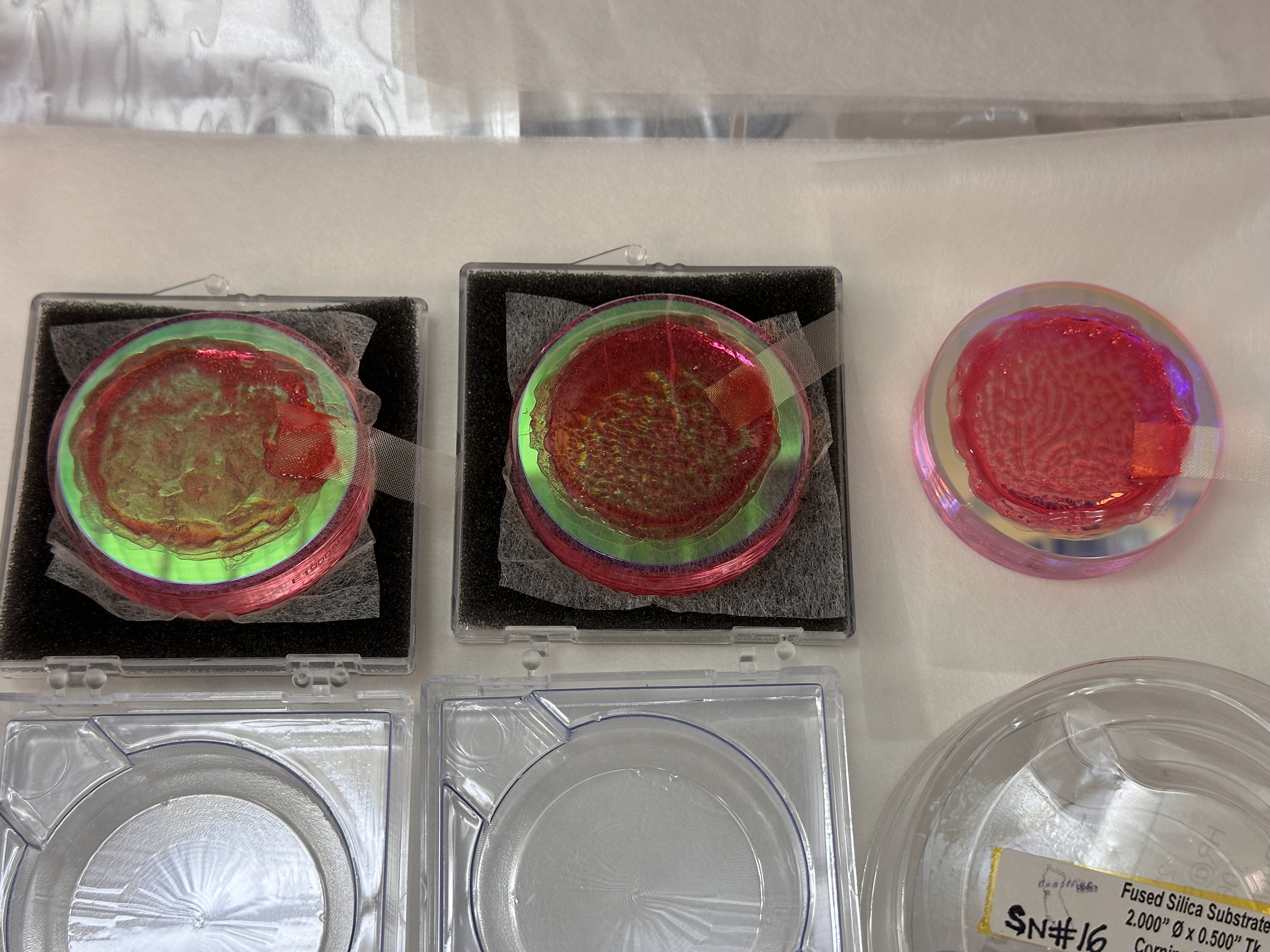
The HR and AR side of all three optics were cleaned using First Contact - see picture attached for reference.