jeffrey.kissel@LIGO.ORG - posted 13:55, Monday 01 December 2025 - last comment - 14:12, Monday 01 December 2025(88280)
h1susey DAC Upgrade: SUS ETM / TMS Simulink Model Prep for 28-bit 32CH DACs
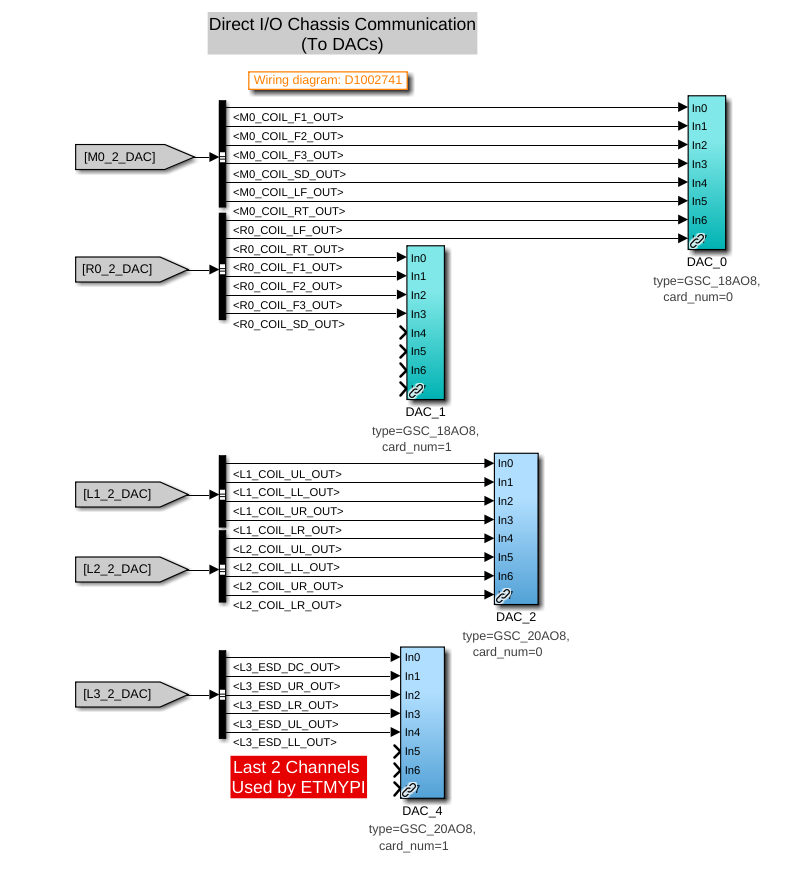
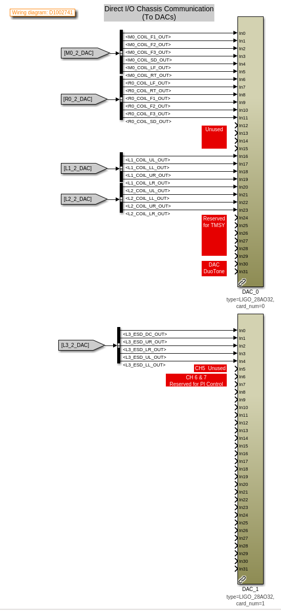
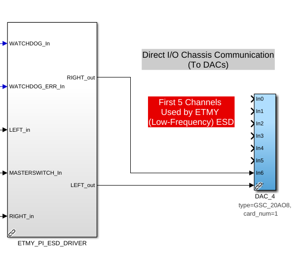
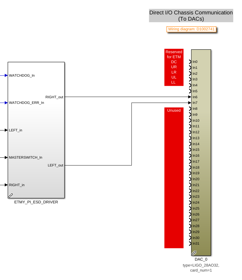
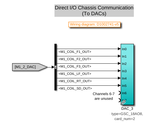
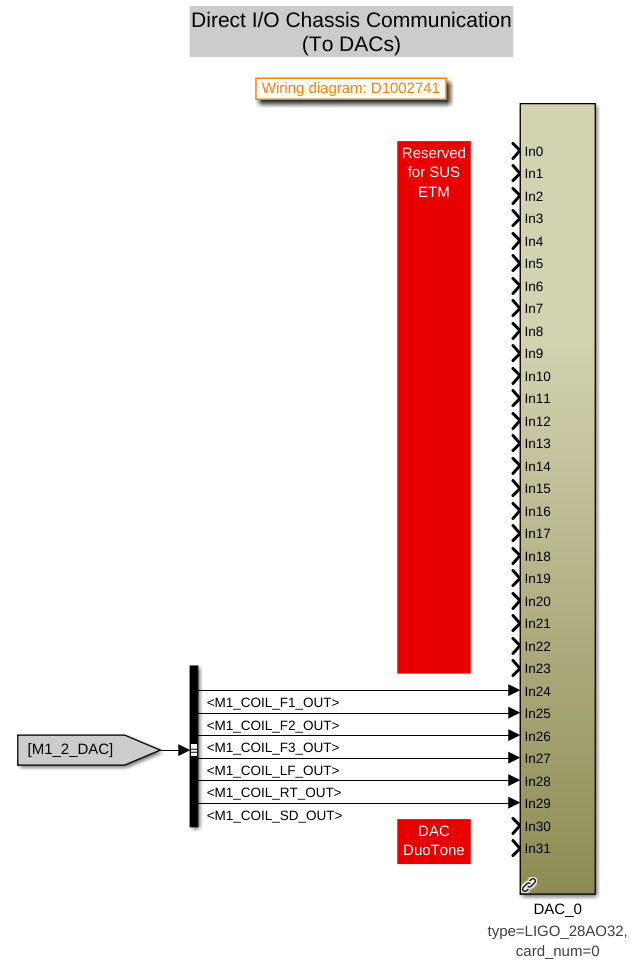
D. Barker, J. Kissel, O. Patane
ECRs: E2400409 and E2500296
IIET: 35739 and 35706, respectively
WP: 12901
DWG: D1002741

Following the solidifying of the wiring plan / IO chassis layout (see LHO:88276), Dave did the lion's share of updating the front-end USER models in prep to the 28-bit 32CH upgrade. I merely reviewed it to make sure we understood all the moving pieces and that the connections to the analog world made sense, and am documenting it here.

Recall -- although the wiring diagram -v11 had shown all 20-bit DACs, in order to best reflect the 2022 ideal as of
    - TST stage :: ECR E1800306 / IIET: 11689,
    - PUM stage :: ECR E1900216 / IIET: 13232
    - Everything else :: ECR E2100485 / IIET:20828,
but H1 had not yet achieved that ideal, as we instead put our money toward developing and waiting for the 28-bit 32CH DACs. As such, in the "BEFORE" shots, you'll see the reality of the mix of 18-bit and 20-bit DACs. In short, the QUAD TOP (M0 and R0) and TMTS TOP (M1) had not yet been upgrade to 20-bit DACs. So those stages now "skip a version" and go straight to 28-bit 32CH DACs (D2200368).

Attached are screen-shots of the DAC section of the user models BEFORE vs. AFTER:
    - h1susetmy BEFORE vs. AFTER
    - h1sustmsy BEFORE vs. AFTER
    - h1susetmypi BEFORE vs. AFTER

I also include a view of the 28-bit 32CH DAC card usage from each model that uses it; a view which better shows the consumption of channels by function across USER models.
    - DAC0 AFTER
    - DAC1 AFTER

This view helps identify some index / naming convention issues with DAC1 (see DAC1 usage screenshot). This DAC controls *only* the TST stage ESD, but spans the h1susetmy and h1susetmypi USER models. In both the susetmy and susetmypi models, the card_num parameter is set to 1 (one). HOWEVER, because the h1susetmy model uses both of the new two DACs (card_num=0 and card_num=1), the card_num=1's block name is DAC_1. In h1susetmypi which only uses the second card (card_num=1 ), it's block name is DAC_0.
It's confusing when you look at it like this, and the RCG (current) forces it to be this way because of IO chassis which have mixed DAC card types (unlike ADCs, which the RCG will happily accept cherry pick ). The solution will be as it has been -- update the MEDM macro files that support the user interface, such that we get the UI showing the signal flow through the USER model output and IOP model output without folks having to think about it.
Images attached to this report


Comments related to this report
Here's the svn rev numbers for the versions I screenshot above
    /opt/rtcds/userapps/release/sus/h1/models/
        h1susetmy.mdl       r34028
        h1susetmypi.mdl     r34029
        h1sustmsy.mdl       r34030