Related: https://alog.ligo-wa.caltech.edu/aLOG/index.php?callRep=87729
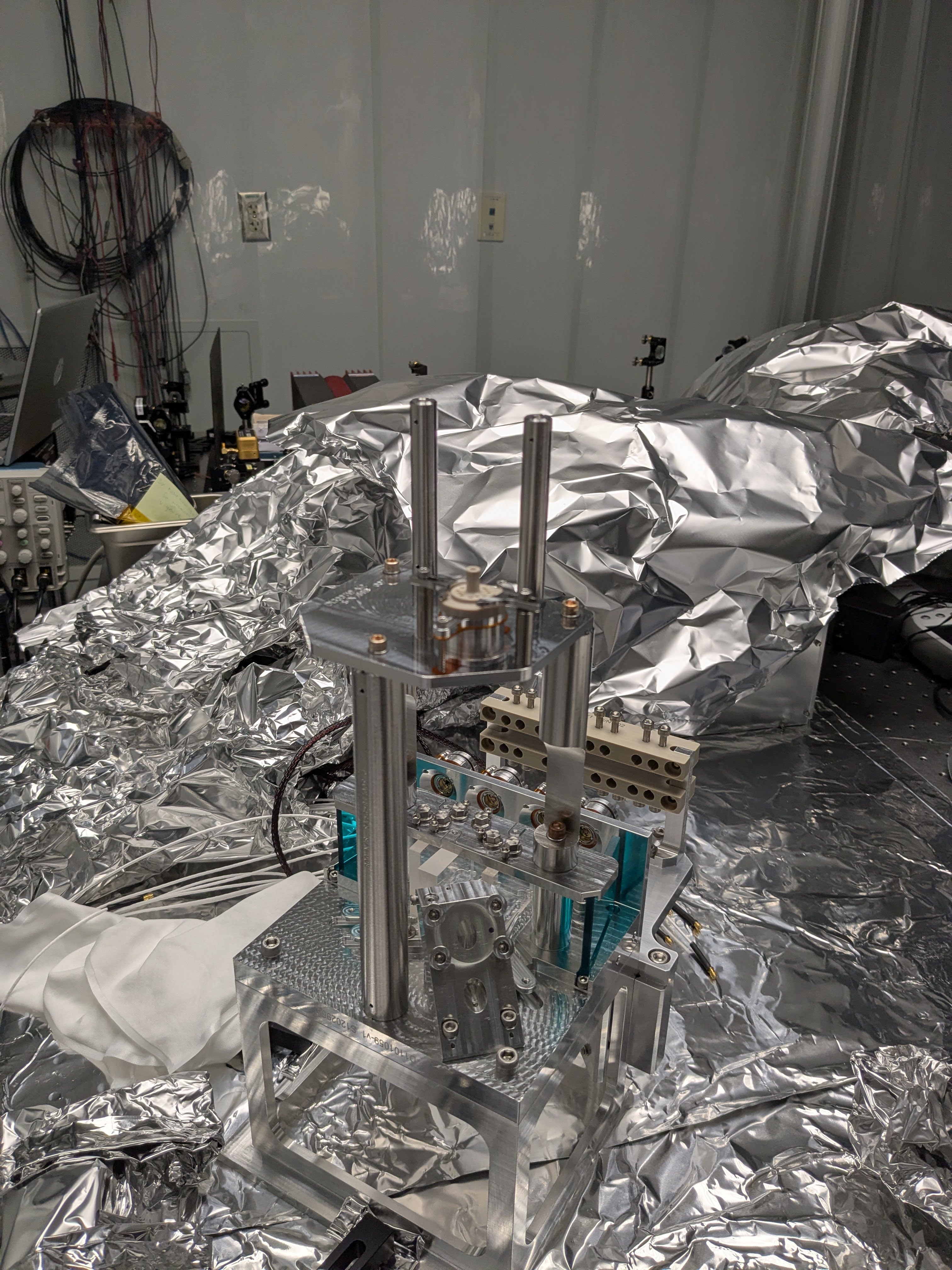
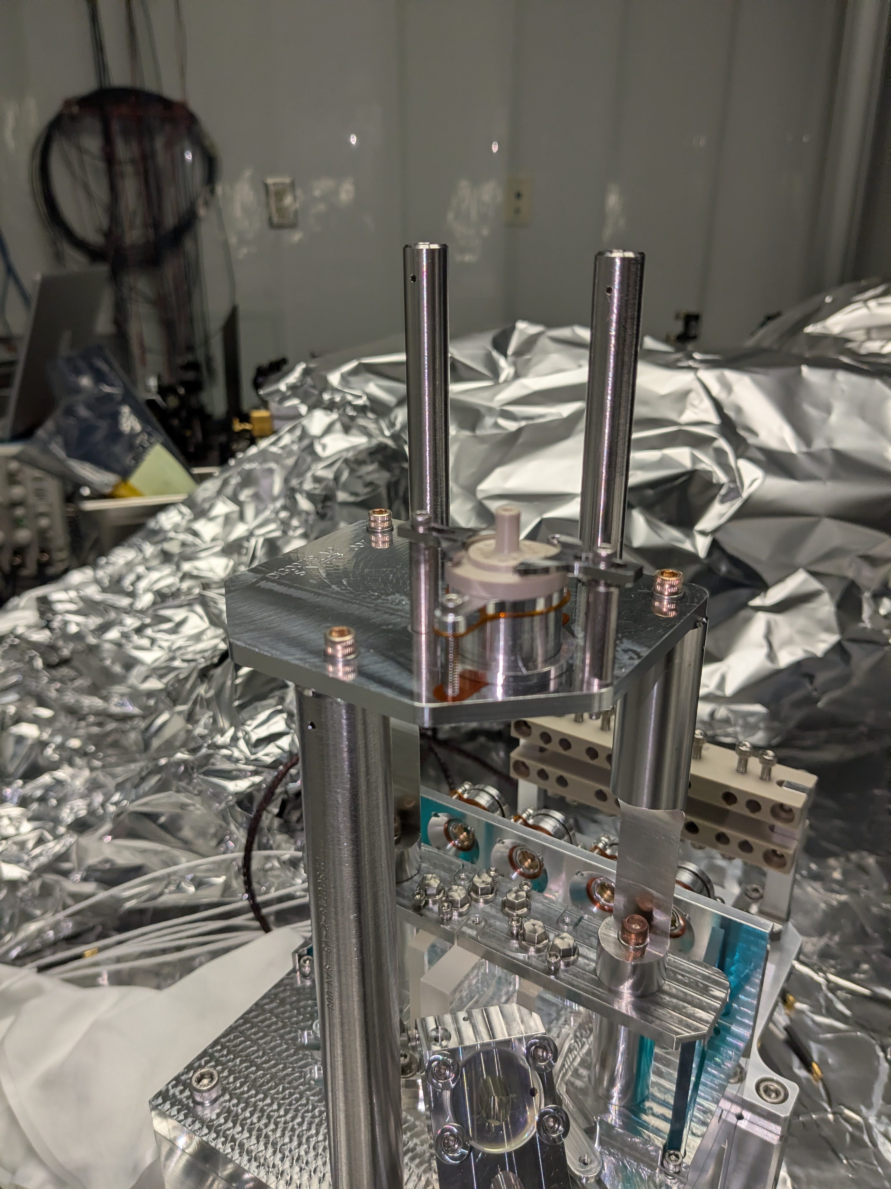
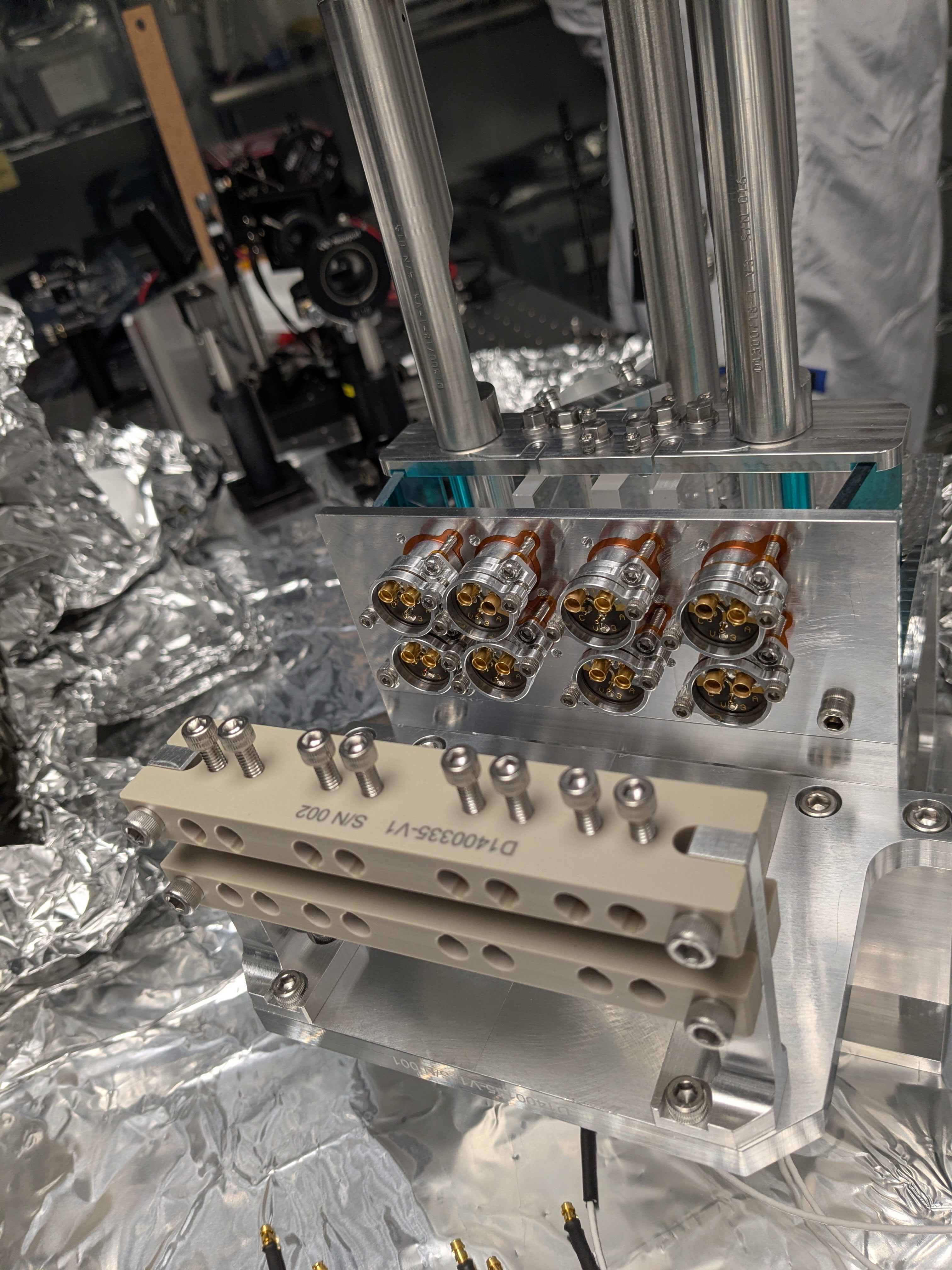
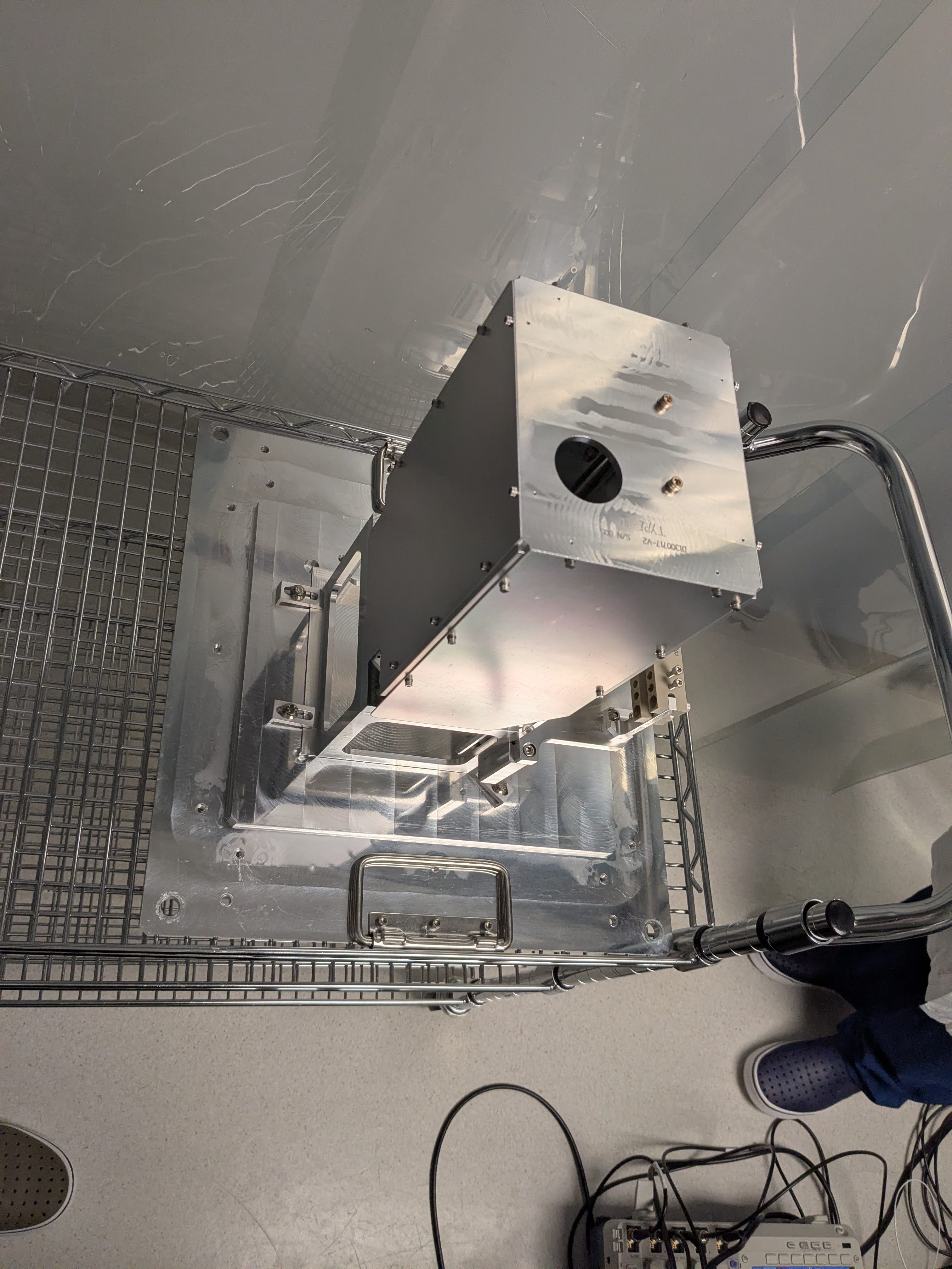
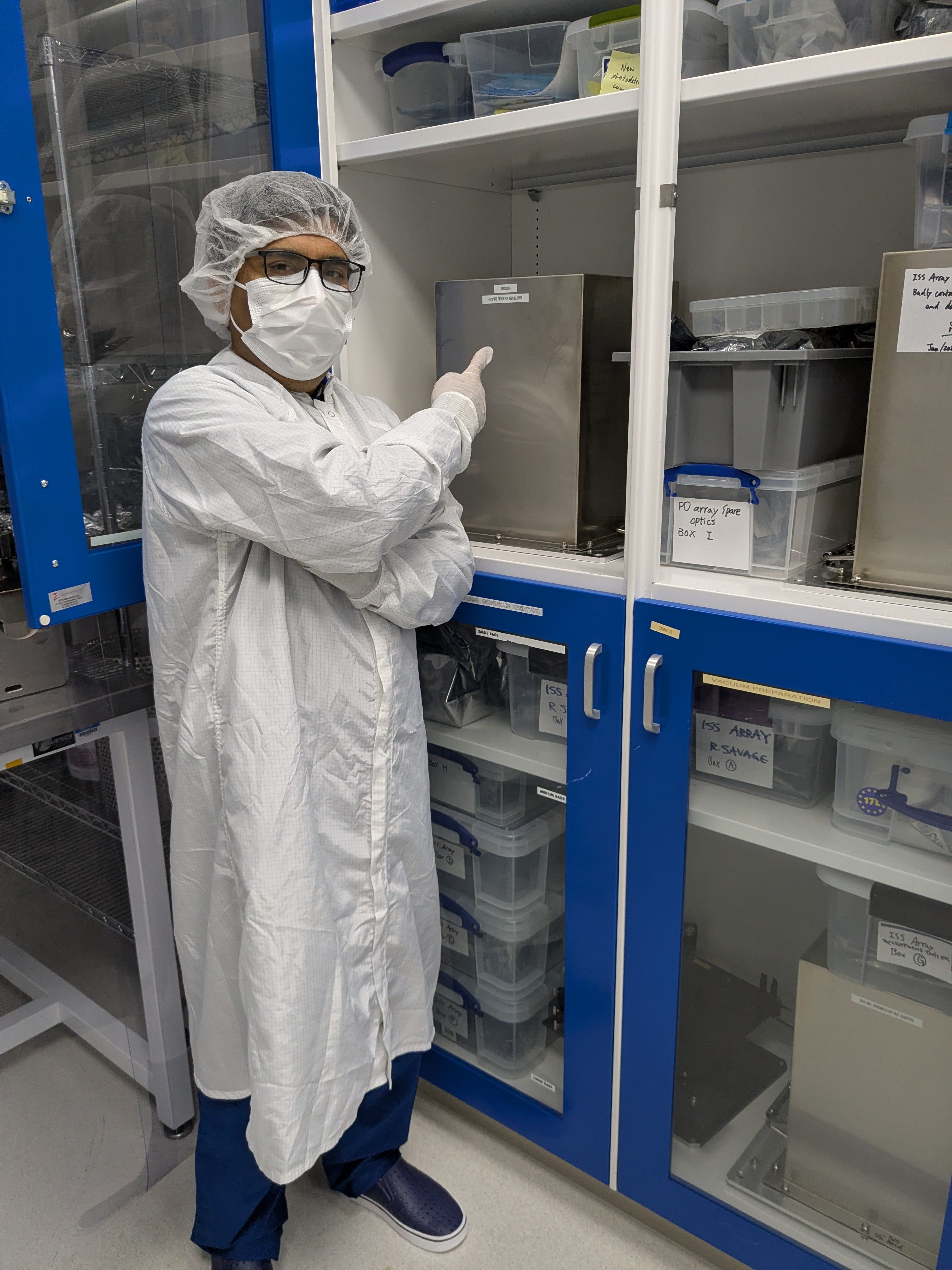
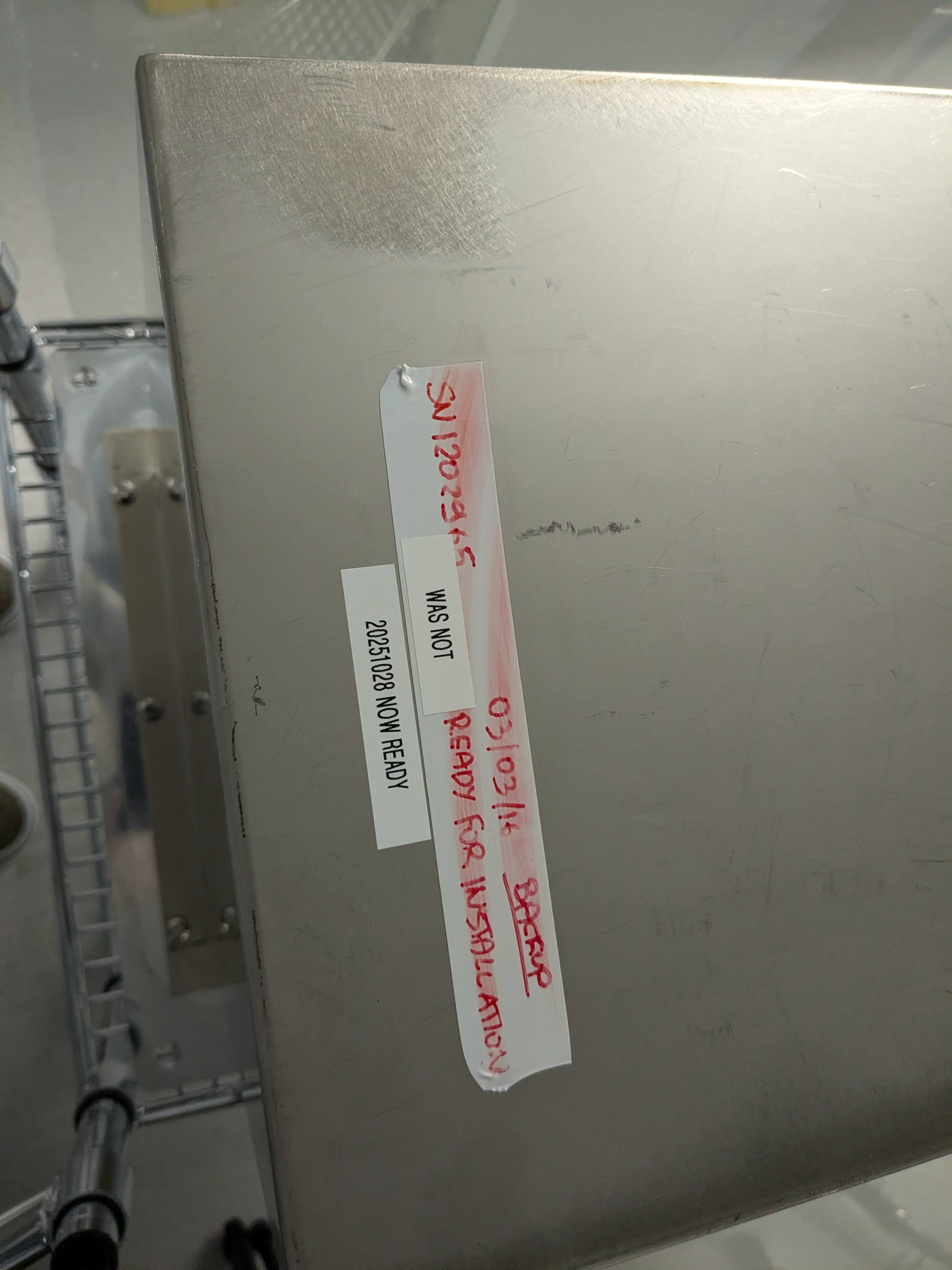
We disconnected everything from the ISS array installation spare unit S1202965 and stored it in the ISS array cabinet in the vac prep area next to the OSB optics lab. See the first 8 pictures.
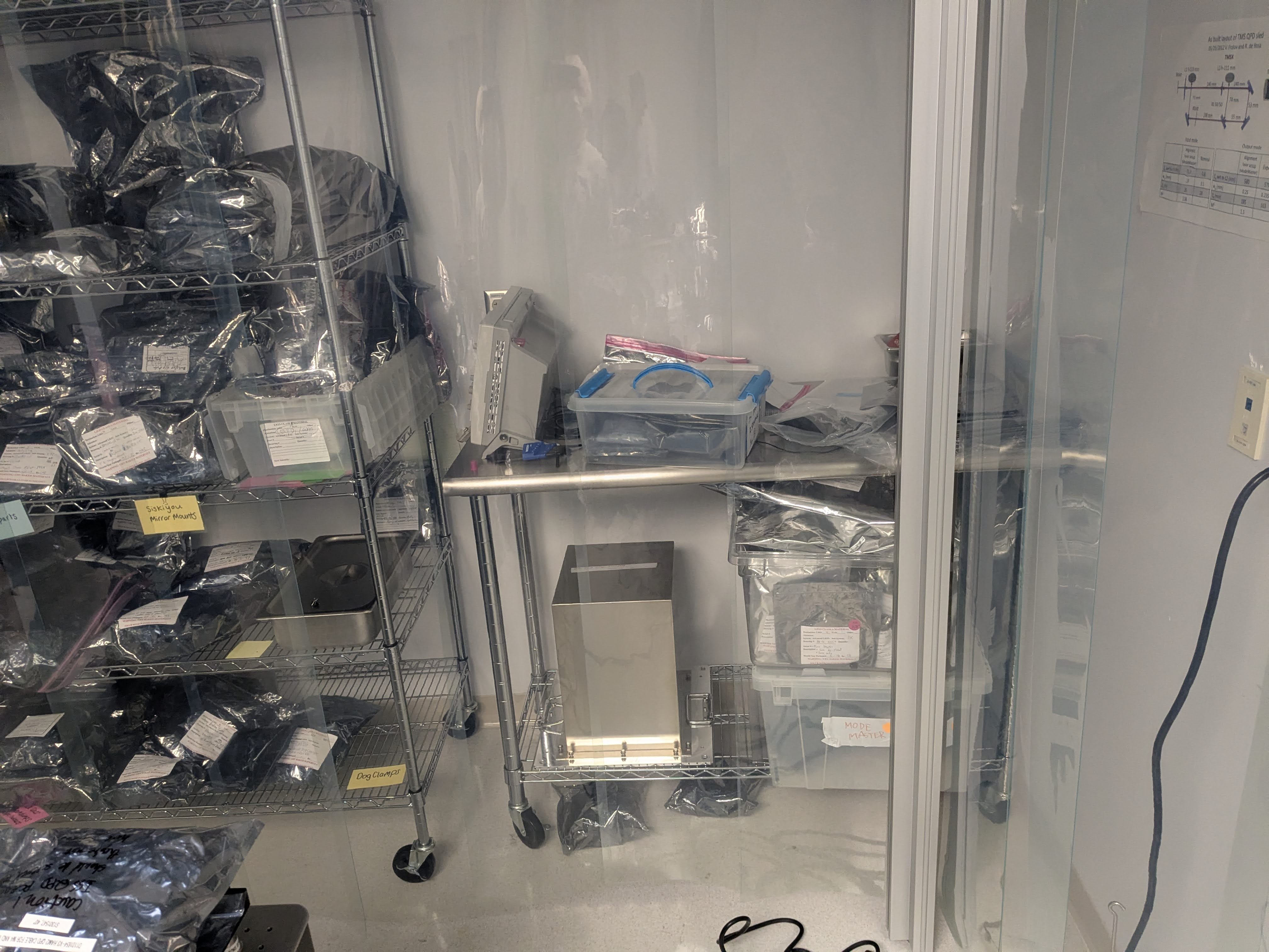
The incomplete spare ISS array assy originally removed from LLO HAM2 (S1202966) was moved to a shelf under the work table right next to the clean loom in the optics lab (see the 9th picture). Note that one PD was pulled from that and was transplanted to our installation spare S1202965.
Metadata for both 2965 and 2966 were updated.
ISS second array parts inventory https://dcc.ligo.org/E2500191 is being updated.
Rahul and I cleared the optics table so Josh and Jeff can do their SPI work.
Optics mounts and things were put in the blue cabinet. Mirrors, PBS and lenses were put back into labeled containers and in the cabinet in front of the door to the change area.
Butterfly module laser, the LD driver and TEC controller were put back in the gray plastic bin. There was no space in the cabinets/shelves so it's put under the optics table closer to the flow bench area.
Single channel PZT drivers were put back in the cabinet on the northwest wall in the optics lab. Two channel PZT driver, oscilloscopes, a function generator and DC supplies went back to the EE shop.
OnTrack QPD preamp, its dedicated power transformer, LIGO's LCD interface for QPD and its power supply were put in a corner of one of the bottom shelf of the cabinet on the southwest wall.
Thorlabs M2 profiler and a special lens kit for that were given to Tony who stored them in the Pcal lab.
aLIGO PSL ISS PD array spare parts inventory E2500191 was updated.
Final jitter coupling values etc. of the installation spare
I was baffled to find that I haven't made an alog about it, so here it is. These as well as other alogs written by Jennie, Rahul or myself in since May-ish 2025 will be added to https://dcc.ligo.org/LIGO-T2500077.
Position of the PDs relative to the beam were adjusted further.
Multiple PDs were moved so that there's no huge outlier in the position of the PDs relative to the beam. When Mayank and Siva were here, we used to do this using an IR camera to see the beam spot position. However, since then we have found that the PD output itself to search for the edge of the active area is easier.
After the adjustments were made, the beam going into the ISS array was scanned vertically as well as horizontally while the PD outputs were recorded. See the first attachment. There are two noteworthy points.
1. PDs "look" much narrower in YAW than in PIT due to 45 degrees AOI only in YAW.
Relative alignment matters more for YAW because of this.
2. YAW scan shows the second peak for most of PDs but only in one direction.
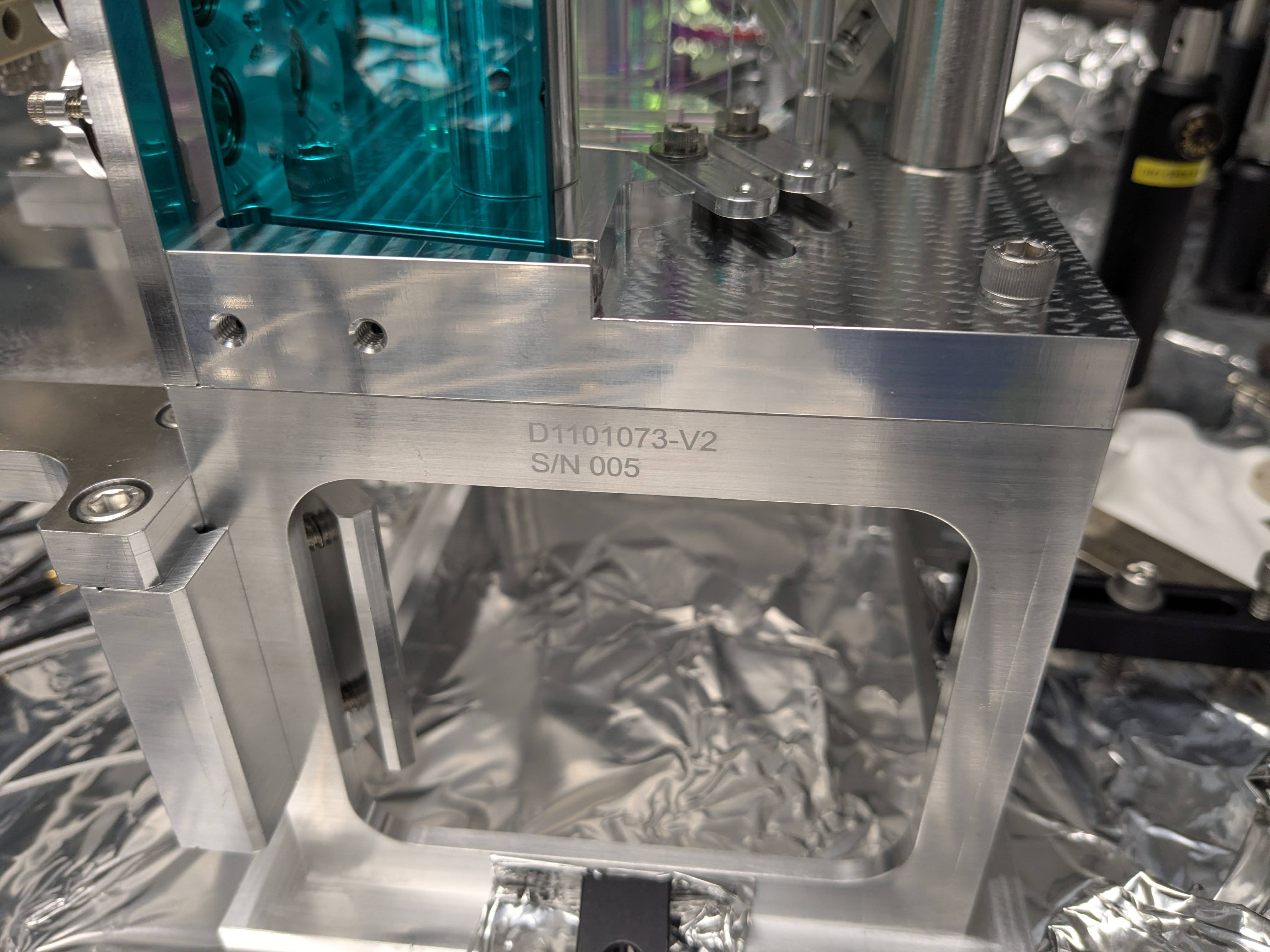
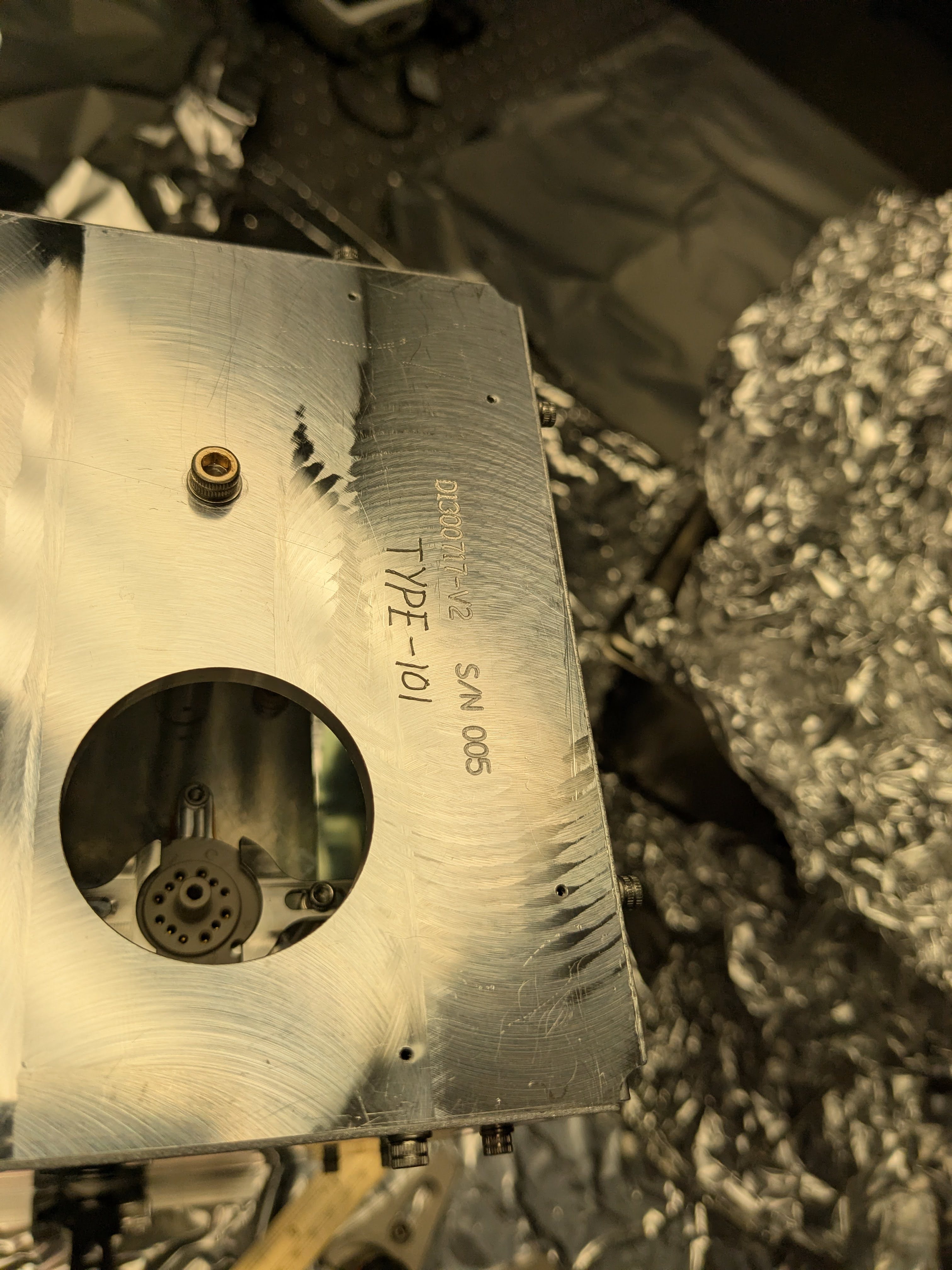
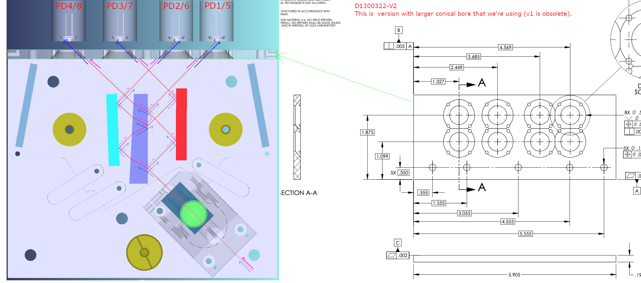
This was observed in Mayank/Siva data too but it wasn't understood back then. This is the design feature. The PDs are behind an array plate like in the second attachment (the plate itself is https://dcc.ligo.org/D1300322). Red lines show the nominal beam lines and they're pretty close to one side of the conical bores on the plate. Pink and blue arrows represent the shifted beam in YAW.
If the beam is shifted too much "to the right" on the figure (i.e. pink), the beam is blocked by the plate, but if the shift is "to the left" (i.e. blue) the beam is not blocked. It turns out that it's possible that the beam grazes along the bore, and when that happens, a part of the broad specular reflection hits the diode.
See the third attachment, this was shot when PD1 (the rightmost in the picture) was showing the second peak while PD2 didn't.
(Note that the v2 plate which we use is an improvement over the v1 that actually blocked the beam when the beam is correctly aligned. However, there's no reason things are designed this way.)
Finding a beam spot position that has a good (small/acceptable) jitter coupling.
We used a PZT-driven mirror to modulate the beam position, which was measured by the array QPD connected to ON-TRAK OT-301 preamp as explained in this document in T2500077 (though it is misidentified as OT-310).
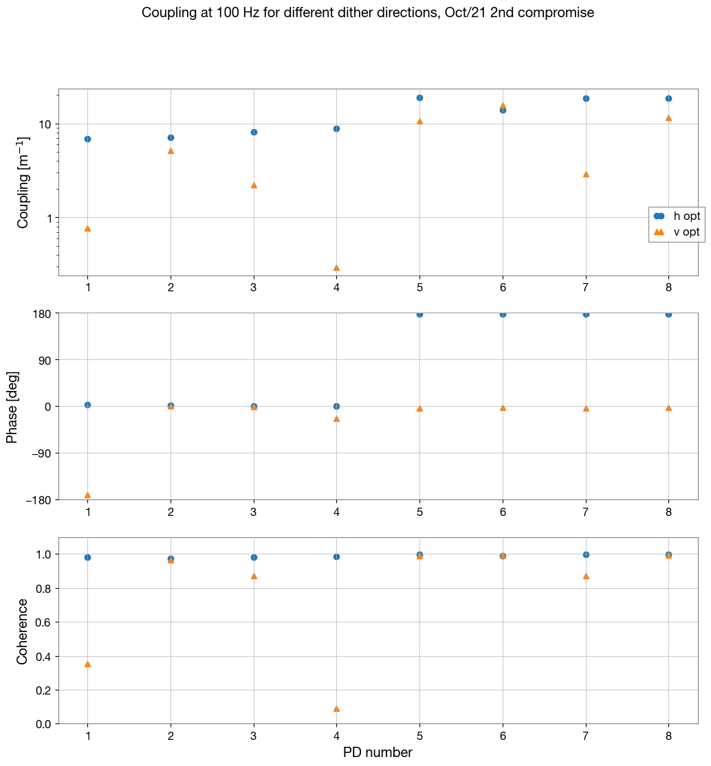
See the fourth attachment where relatively good (small/acceptable) coupling was obtained. The numbers measured this time VS April 2025 (Mayank/Siva numbers) VS February 2016 (T1600063-V2) are listed below. All in all, horizontal coupling was better in April but vertical is better now. Both now and Apr/2025 are better than Feb/2016.
| PD number |
Horizontal [RIN/m] |
Vertical [RIN/m] |
||||
| Now |
Apr/2025 (phase NA) |
Feb/2016 (phase NA) |
Now |
Apr/2025 (phase NA) |
Feb/2016 (phase NA) |
|
|
1 |
6.9 | 0.8 | 20 | -0.77 | 34.1 | 11 |
| 2 | 7.1 | 2.7 | 83 | 5.1 | 2 | 25 |
| 3 | 8.2 | 5.5 | 59 | 2.2 | 4.4 | 80 |
| 4 | 8.8 | 2.3 | 33 | 0.30 | 1.1 | 21 |
| 5 | -19 | 5.1 | 22 | 11 | 12.3 | 56 |
| 6 | -14 | 12.9 | 67 | 16 | 30.4 | 44 |
| 7 | -18 | 10.2 | 27 | 2.9 | 42.7 | 51 |
| 8 | -19 | 5.3 | 11 | 12 | 52.1 | 54 |
Phase of the jitter coupling: You can mix and match to potentially lower jitter coupling further.
Only in "Now" column, the coupling is expressed as signed numbers as we measured the phase of the array PD output relative to the QPD output. Absolute phase is not that important but relative phase between the array PDs is important. The phase is not uniform across all diodes when the beam is well aligned. This means that you can potentially mix and match PDs to further minimize the jitter coupling.
Using the example of this particular measurement, if you choose PD1/2/3/4 as the in-loop PD, the jitter coupling of the combined signal is roughly mean(6.9,7.1,8.2,8.8)=7.8 RIN/m horizontally and mean(-0.77, 5.1, 2.2, 0.3) = 1.7.
However, if you choose PD1/3/4/7 (in analog land), the coupling is reduced to mean(6.9, 8.2, 8.8, -18)=1.5 horizontally and mean(-0.77, 2.2, 0.3, 2.9)=1.2.
You don't pre-determine the combination now, you should tune the alignment and measure the coupling in chamber to decide if you want a different combination than 1/2/3/4.
Note, when monotonically scanning the beam position in YAW (or PIT) edge to edge of PDs, some PDs showed more than one phase flips. When the beam is apparently clipped at the edge (thus the coupling is huge), all diodes show the same phase as expected. But that's not necessarily the case when the beam is well aligned as you saw above.The reason of the sign flips when the beam is far from the edge of the PD is unknown but there should be something like particulates on the PD surface.
QPD adjustment after the good coupling position was established
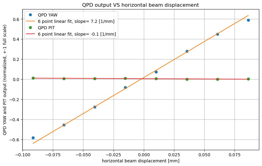
The QPD was physically moved so the beam is very close to the center of the QPD. This can be used as a reference in chamber when aligning the beam to the ISS array.
After this, we manually scanned the beam horizontally and measured the QPD output. See the 5th attachment, vertical axis is directly comparable to the normalized PIT/YAW of the CDS QPD module, assuming that the beam size on the QPD in the lab is close enough to the real beam in chamber (which it should be).


EPO-tagging for ISS Array work