REMOVE SEARCH FILTER
SEARCH AGAIN
Search criteria
Section: H1
Task: IOO
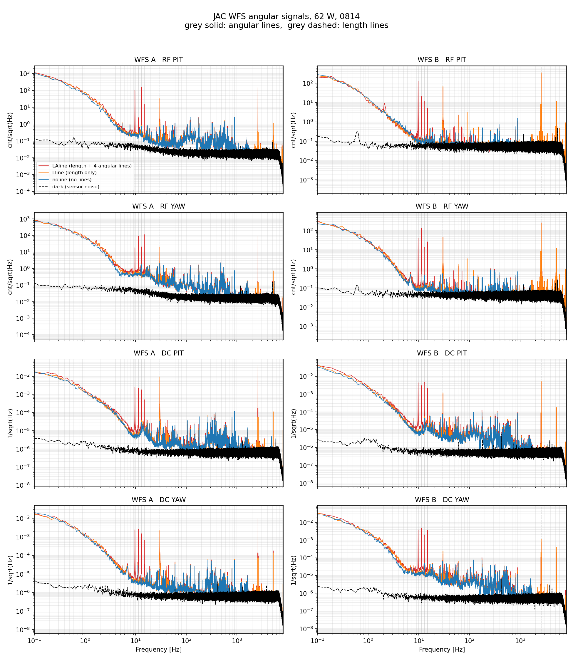
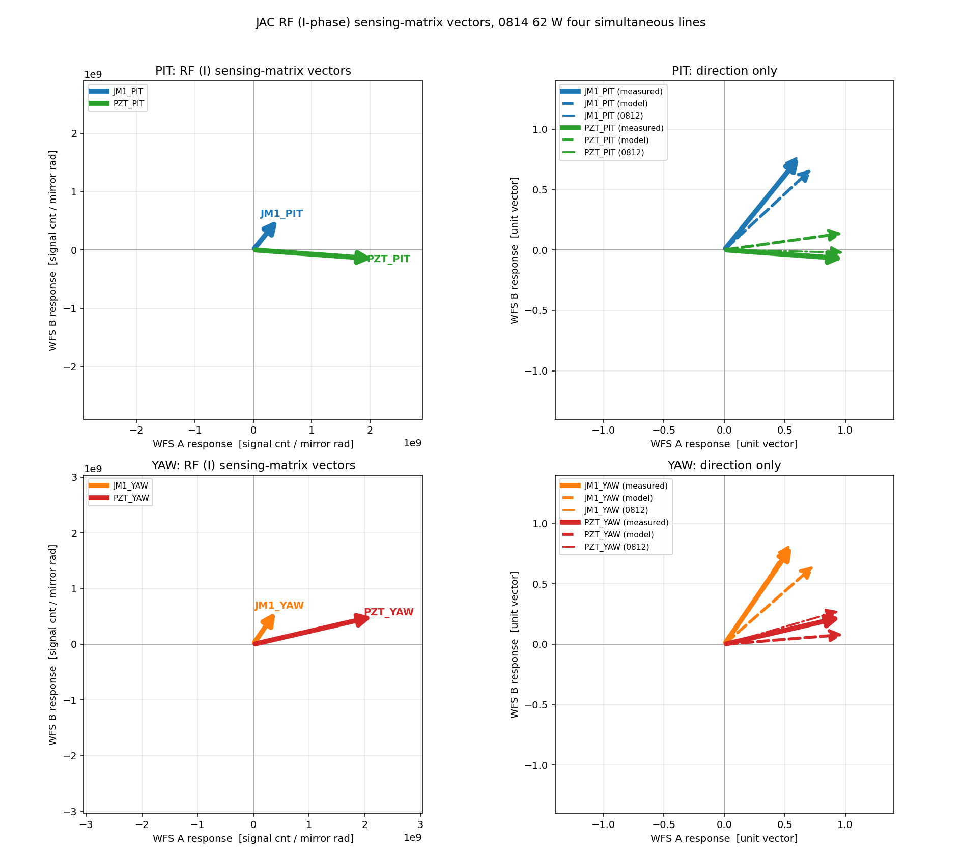
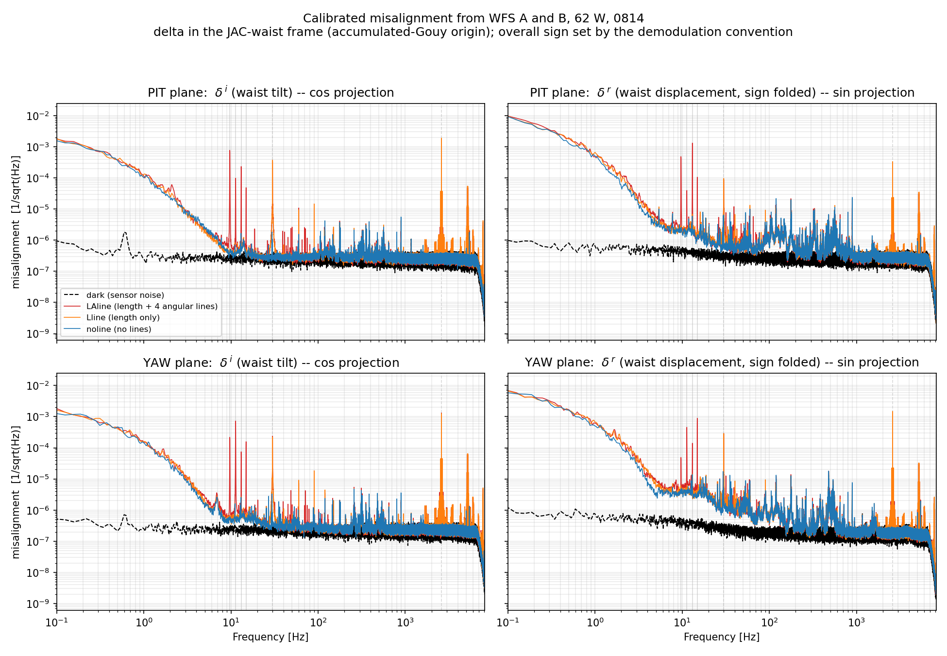
I calibrated the JAC WFS A/B RF signals into the complex misalignment amplitude at the JAC waist, using four angular calibration lines at 62 W (measurement of Aug 14). The sensing matrix agrees with the one measured on Aug 12 and with the layout. Converting the two WFS signals into the real and imaginary parts of the misalignment (δr = lateral shift at the waist, δi = tilt), the displacement part dominates by a factor of 4–5, which is consistent with the dominant jitter source being the PSL which is far (~90 deg of Gouy phase) from the JAC waist.
One question remains: the locked WFS DC does not sense on the plane 90 deg from the RF where it should; the unlocked DC does. Second-order modes are the prime suspect and analysis ongoing.
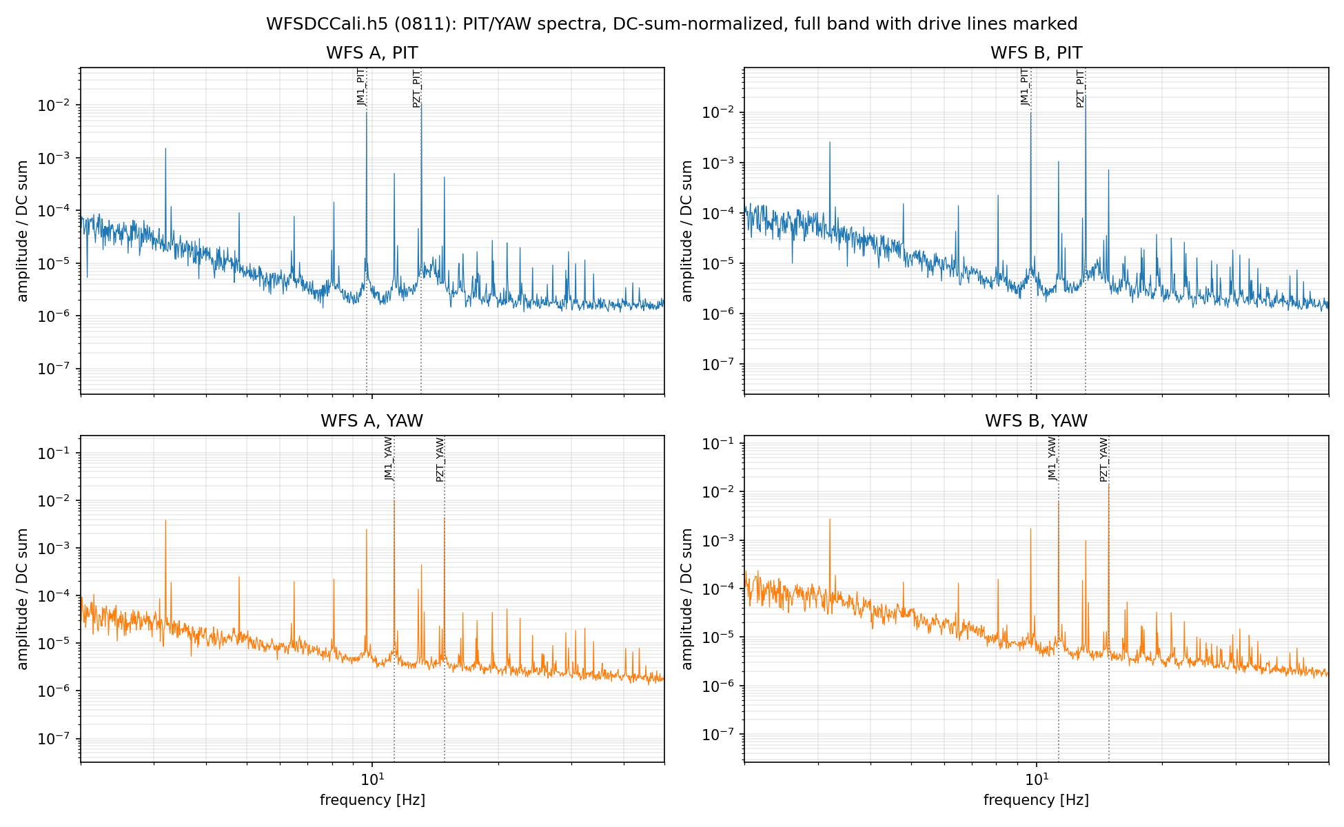
With the cavity locked at 62 W we injected four angular calibration lines and recorded WFS A and B (RF I/Q of all segments, and the DC segments). The raw spectra are in wfs_spectra_0814.png. Three records were taken: all lines on ("LAline"), length lines only ("Lline"), and no lines ("noline"), plus a dark record for the sensor floor. The line list is as follows:
| line | frequency | injected at |
|---|---|---|
| JM1 PIT | 9.7 Hz | SUS-JM1 M1 |
| JM1 YAW | 11.3 Hz | SUS-JM1 M1 |
| PZT PIT | 13.1 Hz | IO PZT tip/tilt |
| PZT YAW | 14.9 Hz | IO PZT tip/tilt |
| length | 30 Hz | cavity length |
| length dither | 2600 Hz | cavity length |
The length lines are not for this post: they provide the demodulation reference for the double-demodulation signal, to be reported separately.
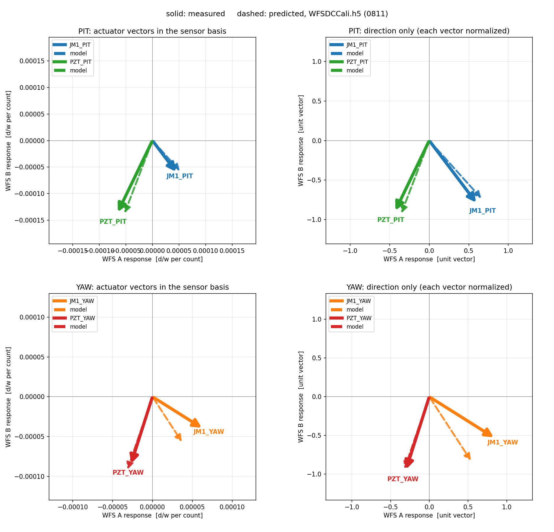
From the heights of the four lines in each sensor we built the two 2x2 sensing matrix (actuator basis). The sensing-matrix vector figure is wfs_sensing_vectors_0814.png; it also carries the same measurement taken on Aug 12 and the layout-model prediction. The two measurement days agree very well. The model deviates by a few degrees per head (up to ~10 deg, table below), which we do not worry about, since WFS placement uncertainties and the actuators' own Gouy-phase uncertainties are of this order.
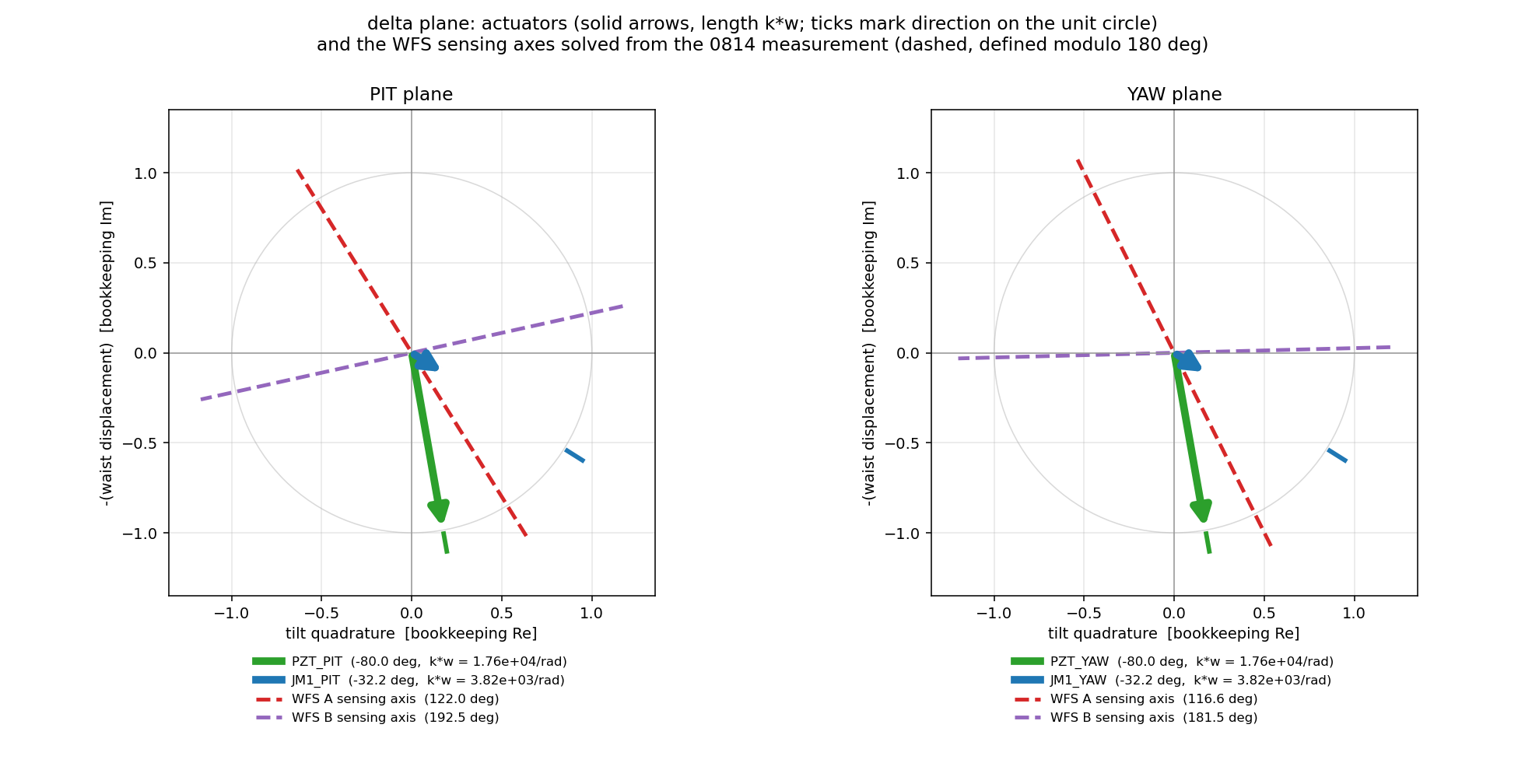
The delta plane is the complex amplitude of the TEM10/01 content referenced at the JAC waist (accumulated Gouy phase = 0 there): the real axis is the waist lateral shift, the imaginary axis the tilt. An actuator kicking by an angle at accumulated Gouy phase ηa drives this amplitude with phase i·eiηa; a sensor reads the projection of the amplitude onto its own axis.
Actuator parameters taken from the layout model (accumulated Gouy referenced to the JAC waist):
| actuator | ηacc [deg] | w at actuator [mm] | k·w [per rad] |
|---|---|---|---|
| PZT (PIT/YAW) | -80.0 | 2.99 | 1.76e4 |
| JM1 (PIT/YAW) | -32.2 | 0.65 | 3.82e3 |
Solving each head's sensing axis from its response to the two actuators of its plane:
| sensor | η measured [deg] | η model [deg] | diff [deg] |
|---|---|---|---|
| A PIT | 122.0 | 120.2 | +1.9 |
| B PIT | 192.5 | 182.4 | +10.1 |
| A YAW | 116.6 | 121.9 | -5.3 |
| B YAW | 181.5 | 185.7 | -4.2 |
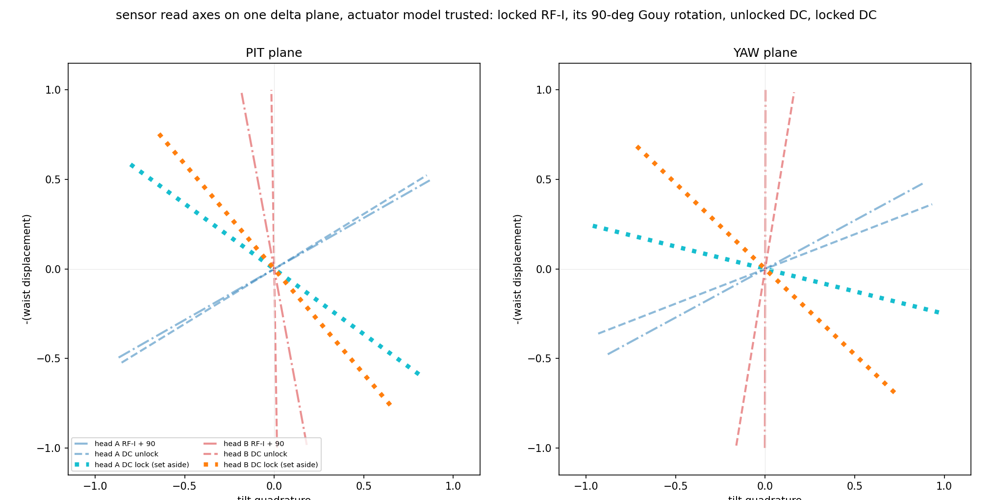
The actuator vectors and sensor axes on the delta plane are drawn in wfs_delta_plane_0814.png.
With these calibration I got the main plot(wfs_delta_spectra_0814.png.) The two WFS signals inverted into the calibrated complex misalignment at the JAC waist, δr (lateral shift) and δi (tilt).
Calibrating the WFS DC the same way should give a sensing plane rotated 90 deg from the RF: the RF reads the tilt-like quadrature at its axis, the DC reads the beam position. But actually, tt does not. In wfs_sensor_gouy_states_0814.png the cyan/orange lines (locked-DC sensing axes) should lie on the blue/red dash-dotted lines (the RF axes rotated by 90 deg), but they point 30–70 deg away. The same solve on an unlocked, clean beam lands within about 10 deg of the expectation, so the sensors themselves are fine: something in the locked field is doing it, and the second-order (mode-mismatch) content is strongly suspected.
The analysis of this signal is in progress and will be posted shortly. Stay tuned.
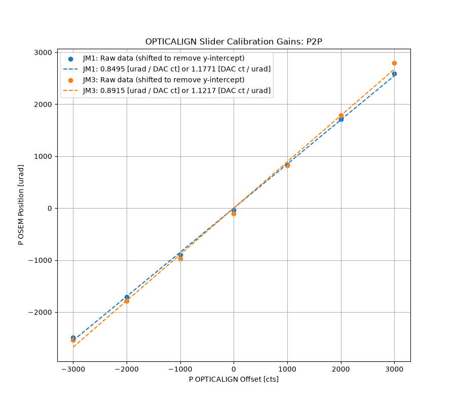
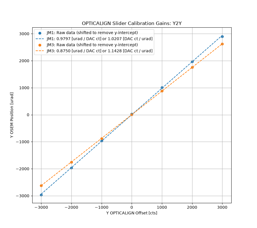
Calibration into urad has been done for JM1 and JM3's OPTICALIGN slider gains. The JM1 P and Y gain values match well with the values Masayuki found using a different method (91487), which is a nice double check.
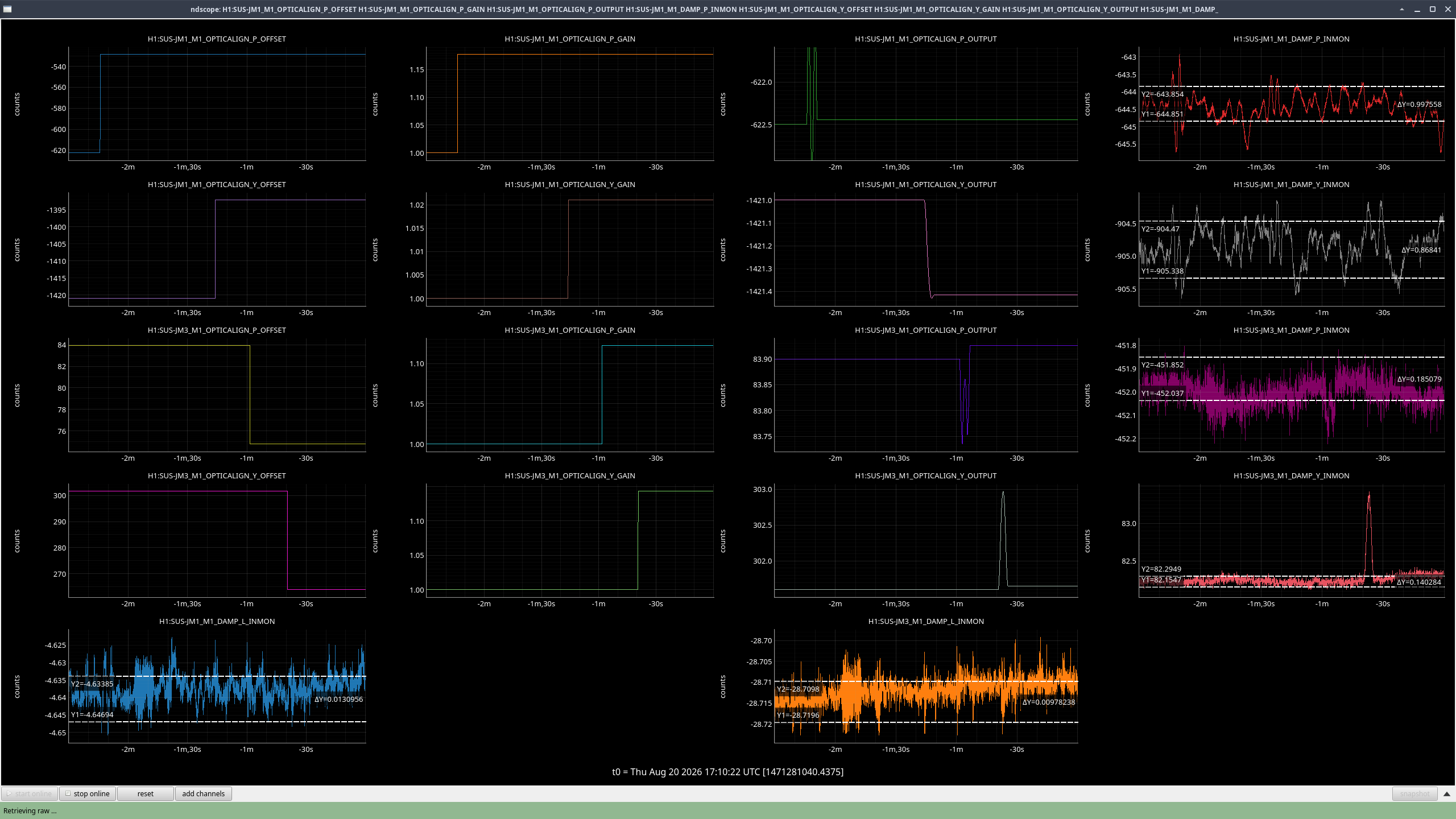
The values to be put in {JM1,JM3}_OPTICALIGN_{P,Y}_GAIN and the necessary changes to the OFFSET values to keep the (current) OPTICALIGN OUTPUT the same are below, and were installed as of 2026/08/20 17:08-17:10UTC. Checking H1:SUS-{JM1,JM3}_M1_DAMP_{P,Y}_IN1 shows that pointing stayed the same before vs after this transition.
NOTE: This means that comparing slider values before vs after this calibration time will not make sense. Instead, you can look at the OPTICALIGN OUT16 values or the pointing using DAMP_IN1 channels since those will stay consistant.
| JM1 | JM3 | |||||
| Calibration Gain [cts/urad] |
OUTPUT (2026/08/19) |
New OFFSET | Calibration Gain [cts/urad] |
OUTPUT (2026/08/19) |
New OFFSET | |
| P | 1.1771 | -622.5 | -528.8420695 | 1.1217 | 83.9 | 74.79718285 |
| Y | 1.0207 | -1421 | -1392.181836 | 1.1428 | 301.6 | 263.9131957 |
Finding Calibration Gains
I used the method Jeff used in 77211 to get the counts -> urad calibration. So now when you move the OPTICALIGN slider by 1 in {Pitch,Yaw}, you actually get 1 urad in movement in {Pitch,Yaw}.
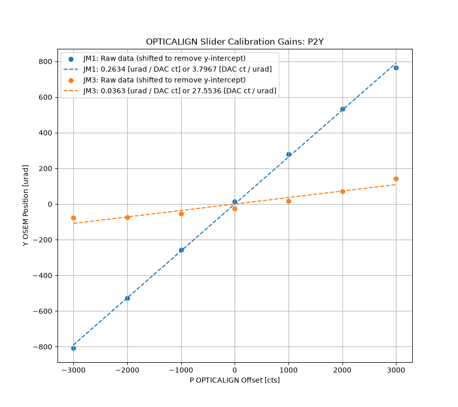
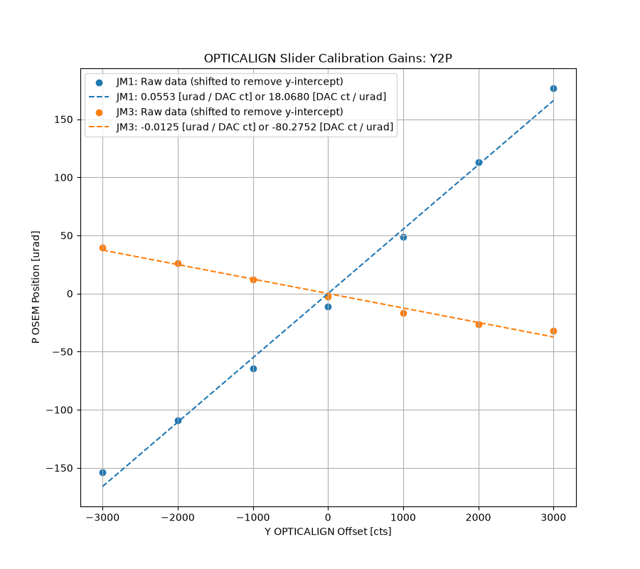
For each suspension, I put a series of OPTICALIGN offsets into Pitch and then into Yaw (only doing one dof at a time). At each offset, I wrote down the resulting values for DAMP_P_IN1 and DAMP_Y_IN1. Using these values I was able to fit a line for P2P, Y2Y, P2Y, and Y2P. I then inverted the slopes to get the calibration values in counts/urad.
On each plot I show the data points with the offsets removed (removed the 'b' from y=mx+b) for ease of slope comparison, and then also plotted the best fit line.
Both suspensions seem to have similar P2P and Y2Y as each other, but the cross-coupling is different. JM1 is a lot more cross-coupled with both P2Y and Y2P than JM3.
Finding New OFFSETs
OFFSET x GAIN = OUTPUT, and we want the OUTPUT to be the same as before, so we can just plug in our new GAINs and the OUTPUT that we want (aka the previous OUTPUT) and solve for OFFSET = OUTPUT / GAIN.
Jennie Wright, Masayuki Nakano, Khanh Vu
Masayuki’s Math
We previously made an attempt to balance the JAC’s reflected beam on the WFS quadrants. However, Masayuki realized that this might not be a fair measurement because the voltage is defined as Voltage = Gain x Power, and the gain can be different for each segment.
To obtain a quantity that can be compared between segments, we instead excite the beam. For example, we can move the beam to the upper half of the WFS (Segments 1 and 2) so that no light lands on the lower half (Segments 3 and 4). If we then drive the beam in yaw with a sine wave, the total power on Segments 1 and 2 must be conserved. Therefore, any change in power on one segment results in a corresponding negative change on the other segment.
The powers on Segments 1 and 2 can then be written as:
P1 = P1_DC + ΔP sin(wt)
P2 = P2_DC - ΔP sin(wt)
Since Voltage = Gain x Power,
V1 = G1 x (P1_DC + ΔP sin(wt))
V2 = G2 x (P2_DC - ΔP sin(wt))
At the excitation frequency, the amplitudes of the power changes on the two segments are equal and opposite. Therefore, taking the ratio of the measured AC amplitudes gives the gain ratio G1/G2.
Applying the same procedure, we can measure G1/G2, G2/G3, G3/G4, and G1/G4. However, we can also infer G1/G4 from the first three ratios:
G1/G4 = (G1/G2) x (G2/G3) x (G3/G4)
Comparing this inferred value with the directly measured G1/G4 gives us a consistency check.
Measurement Procedure
We performed this measurement by injecting an excitation into the JM1 suspension system. Before doing so, we opened the ASC loops and paused the JAC Guardian. We used the picomotors to move the beam onto different halves of the wavefront sensors.
For precision, we monitored the DC signals from the individual segments. Using the same example, when positioning the beam on the upper half, we moved it until there was essentially no signal on Segments 3 and 4. We then balanced the beam in yaw so that the DC signals on Segments 1 and 2 were approximately equal. An example dtt for this step is attached below.
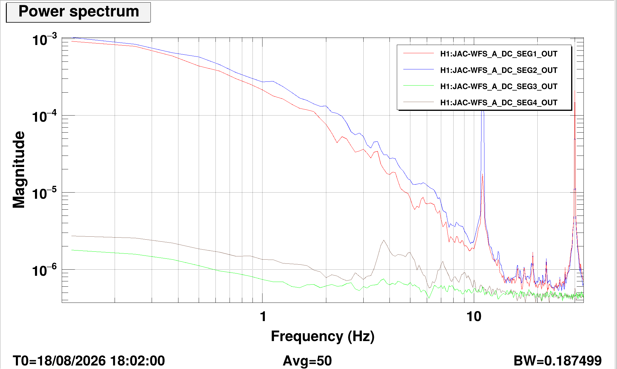
The excitation was a sine wave at 11 Hz with an amplitude of 12. For the upper and lower halves, we injected in yaw. For the left and right halves, we used pitch excitation. The power spectrum plot is also attached below.
Results
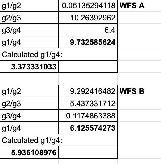
We measured the segment responses at 11 Hz and divided the corresponding amplitudes to obtain the gain ratios. The results are shown below.
For WFS A, the directly measured G1/G4 does not agree well with the value inferred from the other three ratios. For WFS B, the directly measured and inferred G1/G4 values agree considerably better.
However, the calculated results themselves do not seem physically reasonable, since they imply that the gains of different segments can differ by as much as a factor of 10.
Next Step
We suspect that this issue comes from performing the measurement while the JAC was locked. In this condition, the reflected beam contains significant higher-order-mode content, making it difficult to position and balance the beam cleanly on the WFS quadrants.
We will therefore repeat the measurement tomorrow with the JAC unlocked.
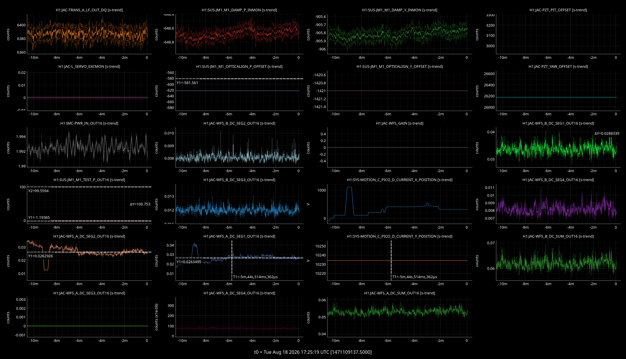
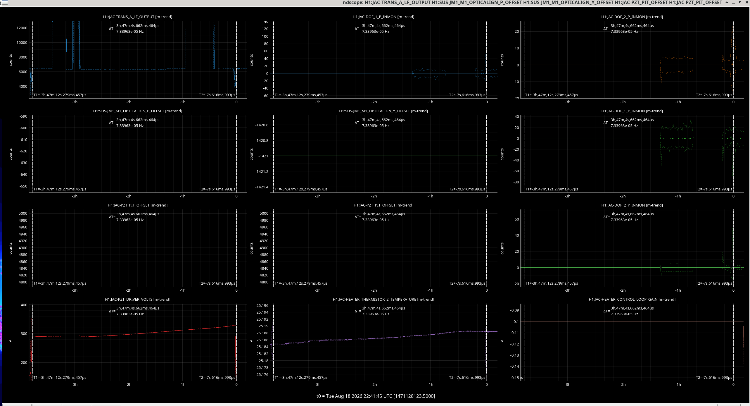
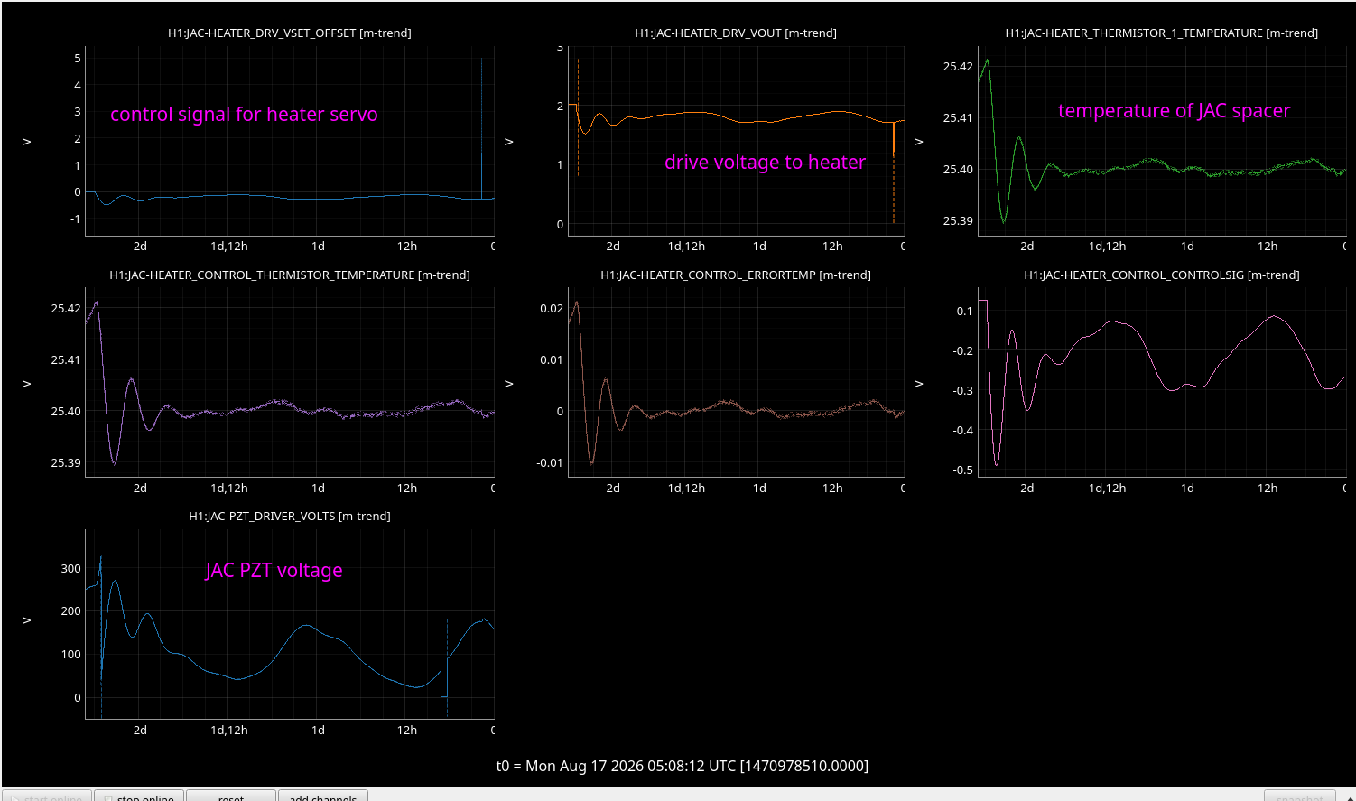
JAC Heater ran out of range this afternoon and the JAC unlocked. We started this lock stretch (first x cursor) already at a pretty high PZT offset so I might add a upper limit to how high a voltage we should lock at.
I have increased the gain magnitude in the heater control servo from -0.1 to -0.15 to try and stop this happening again before this evening when we will increase the power set value from 1.5 W to 3W to give us more headroom above ambient temperature for the servo.
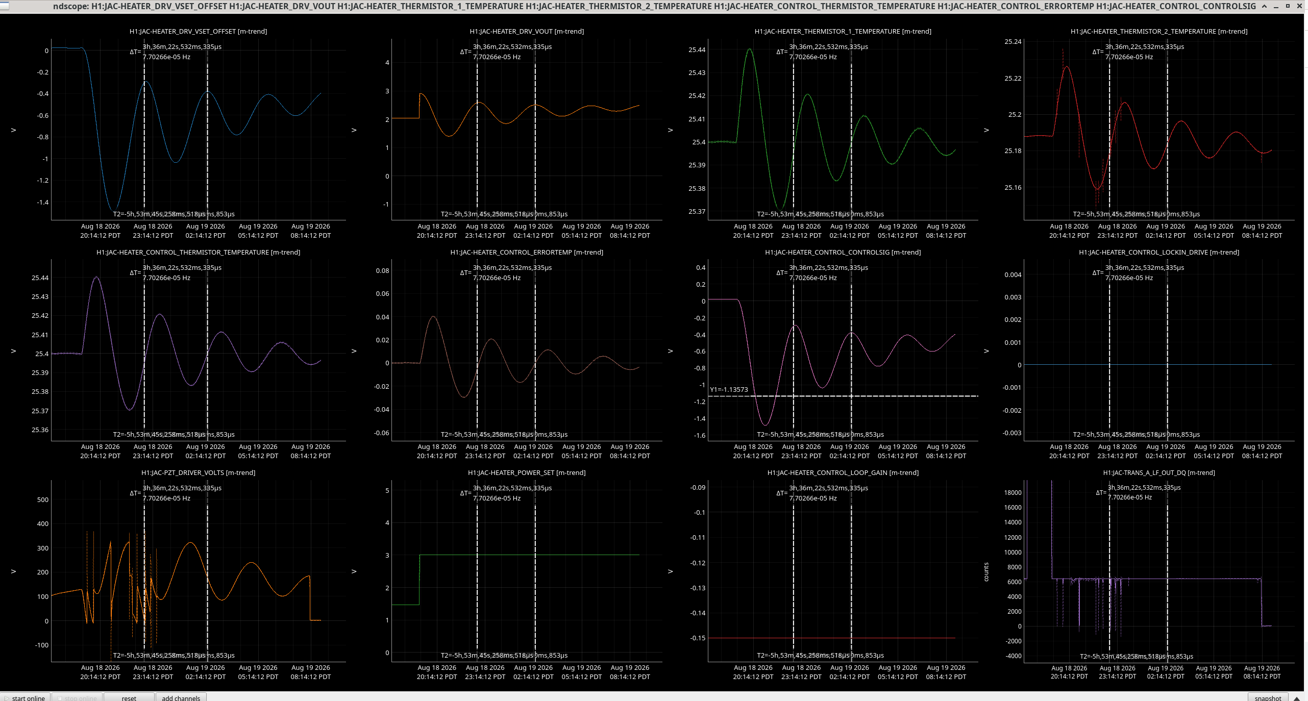
Here is a plot including the control signal. With the lockloss at the first cursor and the gain change at the second.
The JAC locked again at a much lower voltage and so stayed locked until the planned increase in the set power to 3W last night caused some locklosses.
The system looks underdamped from this step response so I will test some changes to the controller over the weekend.

I aaded an upper limit to the SCANNING state in the JAC_LOCK guardian it will only scan up to 300V instead of 330V, this should prevent the cavity locking near the upper limit of the PZT.
Loaded and committed the guardian.
JAC length dither line at 809Hz is on. I also editted the Guardian so that he won't disable it.
It will keep engaged for a couple of days.
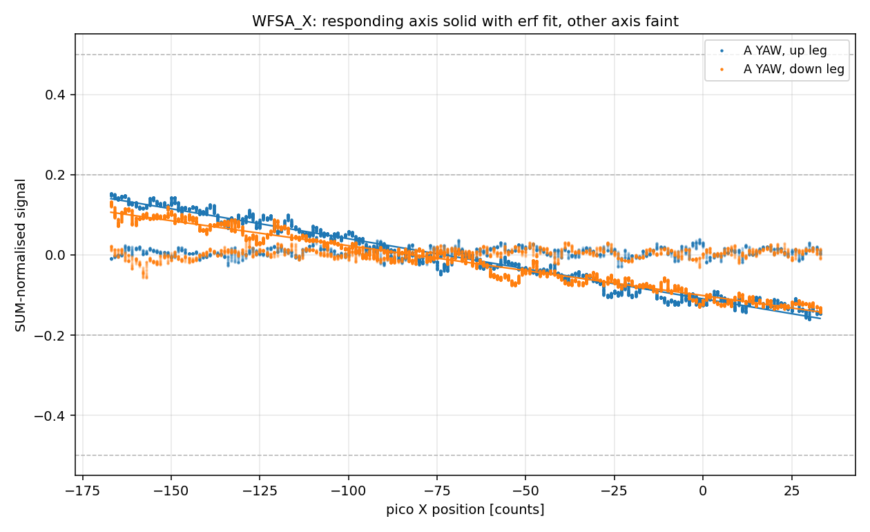
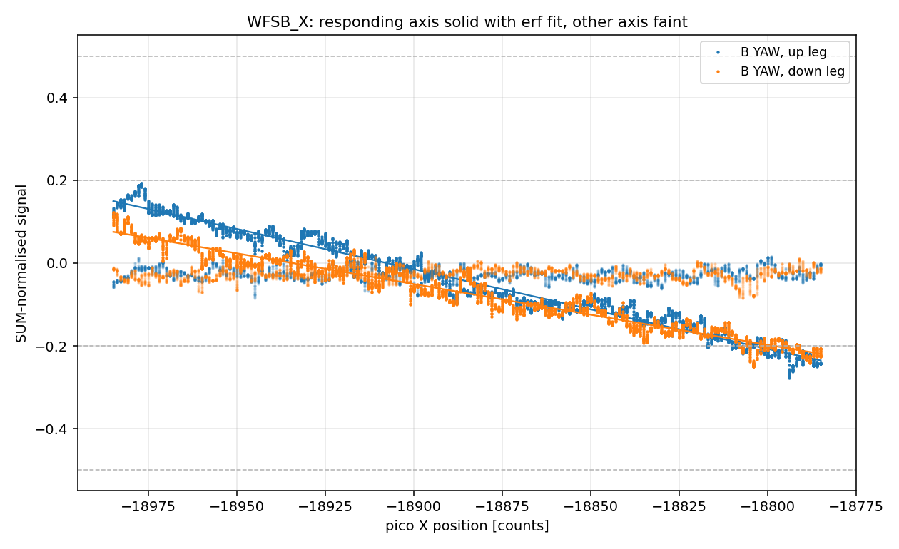
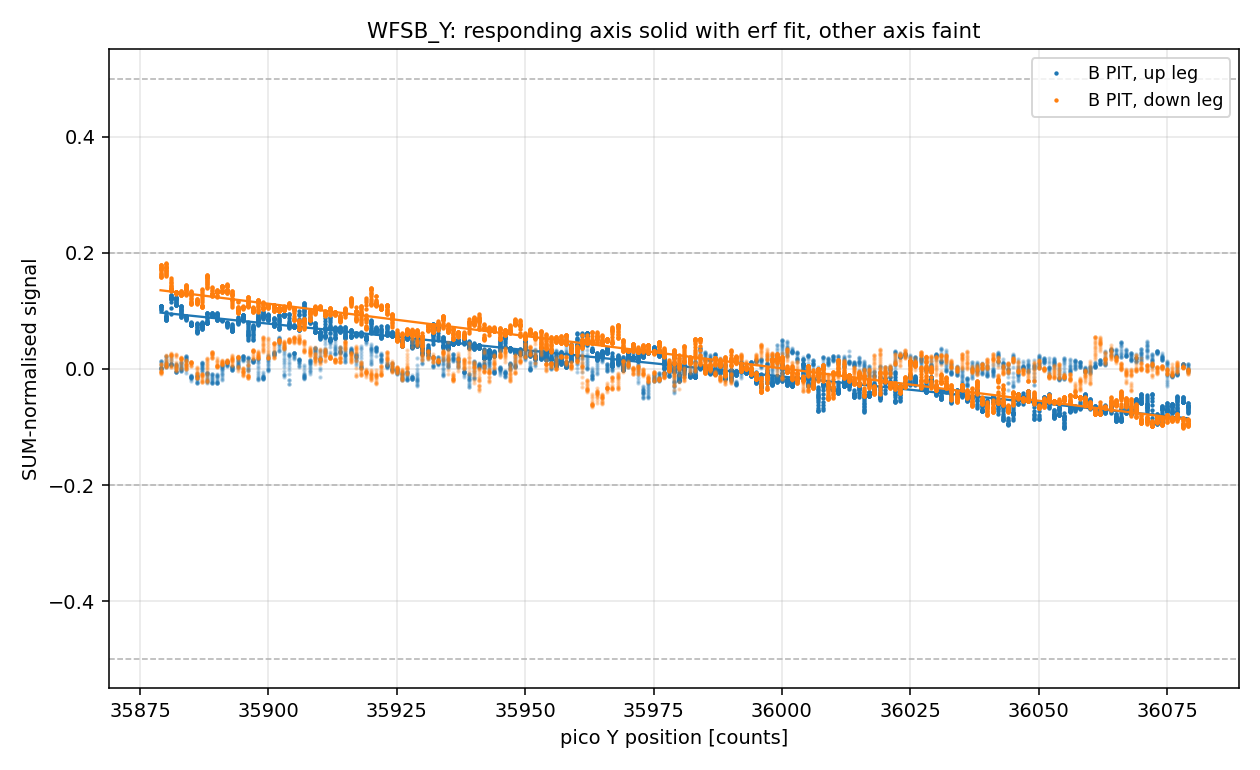
All four JAC pico axes (heads A and B, X and Y motors) have been calibrated in counts to beam displacement on the WFS, by non-locked sweeps read through the WFS DC signals. Efficiencies come out at 0.6–1.2e-3 beam radii per count (0.09–0.19 μm, 0.8–1.6 μrad of beam pointing), with a direction dependence of 9–27 %.
The fit gives the efficiency in beam radii (d/w) per count. Beam radii at the QPDs from the JAC reflected-path optical model:
| plane | wx [μm] | wy [μm] |
|---|---|---|
| WFS A | 199.4 | 181.0 |
| WFS B | 150.0 | 155.9 |
Denominator: SYS-MOTION_C_PICO_D_CURRENT_X/Y_POSITION [counts] of the swept motor. "up" / "down" refer to the sign of the count sweep.
| pico / motor | QPD axis | direction | d/w per count | μm per count | μrad per count (beam) |
|---|---|---|---|---|---|
| A / X | A YAW (x) | up | -9.41e-4 | 0.188 | 1.64 |
| A / X | A YAW (x) | down | -7.82e-4 | 0.156 | 1.36 |
| A / Y | A PIT (y) | up | -7.33e-4 | 0.133 | 1.16 |
| A / Y | A PIT (y) | down | -8.05e-4 | 0.146 | 1.27 |
| B / X | B YAW (x) | up | -1.22e-3 | 0.183 | 1.60 |
| B / X | B YAW (x) | down | -9.32e-4 | 0.140 | 1.22 |
| B / Y | B PIT (y) | up | -5.72e-4 | 0.089 | 0.78 |
| B / Y | B PIT (y) | down | -7.00e-4 | 0.109 | 0.95 |
Attachments: per-axis sweep figures (normalized signal against pico counts).

Jennie W,
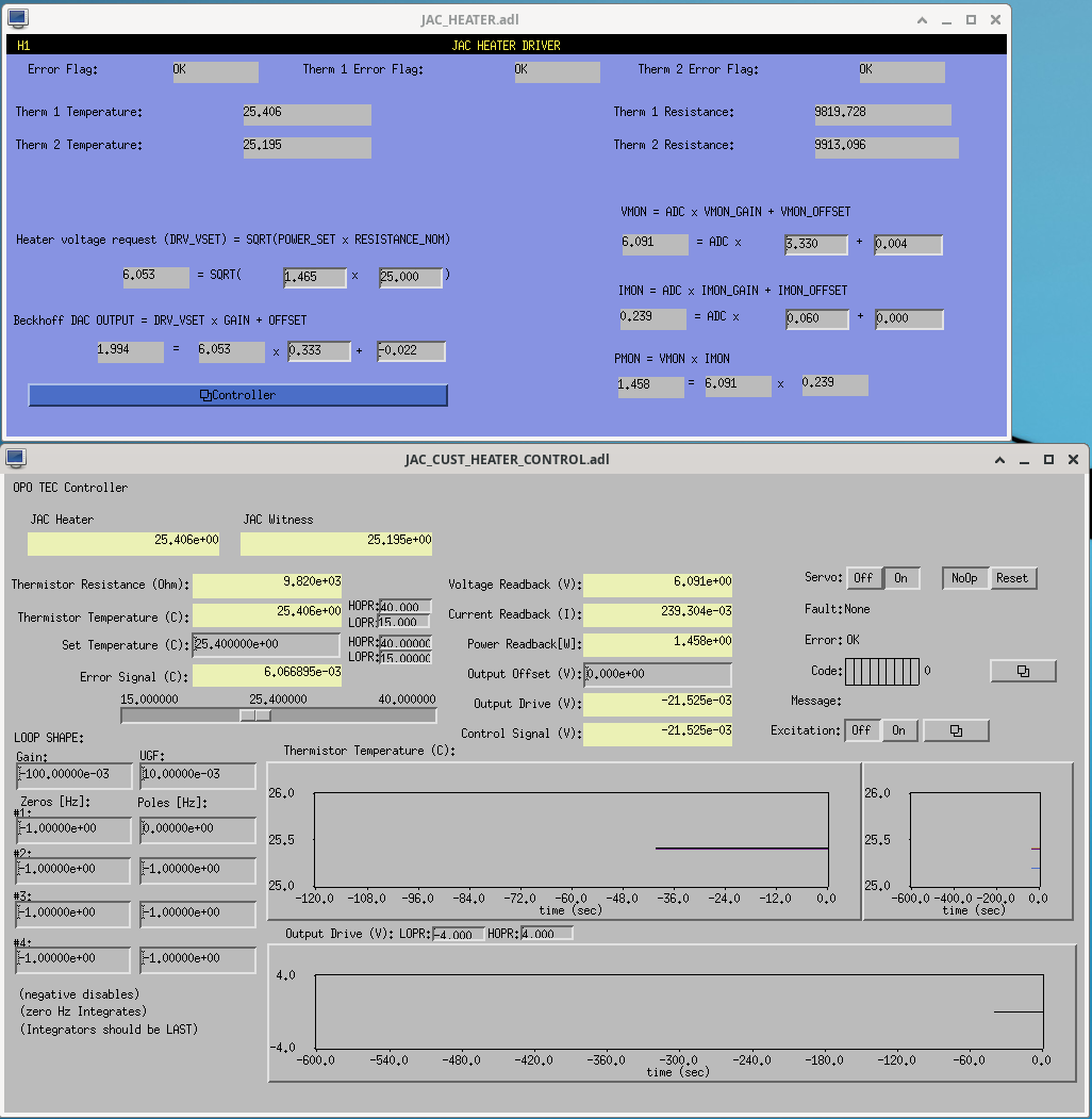
Since Daniel put in a TEC controller for the JAC temperature servo we will no longer use the current version of the guardian control loop so I have set JAC_HEATER guardian to SERVO_OFF. The TEC is turned on and the set point is at 25.4 Degrees C.
The servo controller can be reached by going to sitemap->IOO->JAC Overview->Controller. To turn it off select the 'OFF' button in the top right corner of the controller. The loop can be measured by using the excitation button noted in the picture.
I will trial this over the weekend so I can double check it doesn't drive the JAC away from the control point.
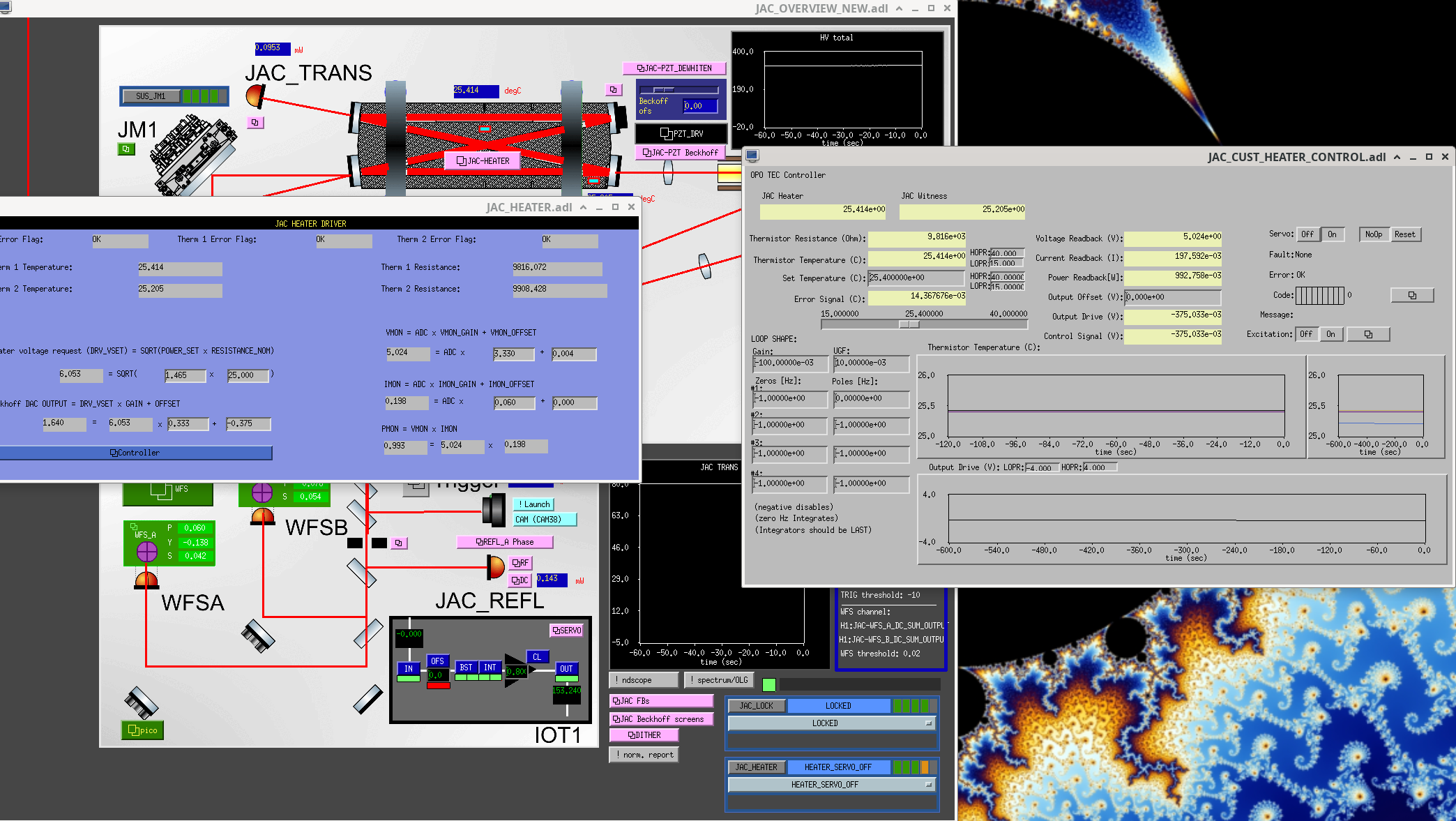
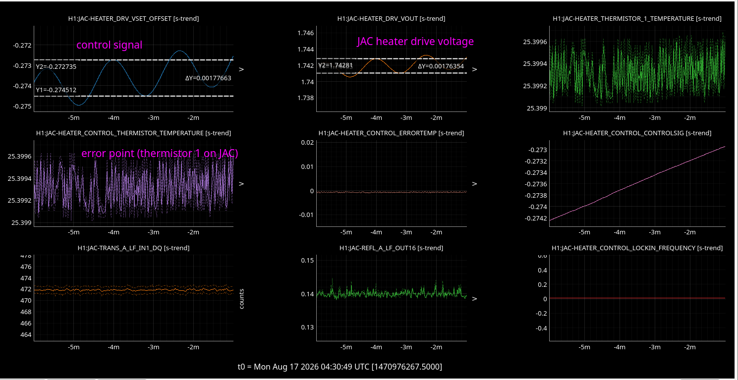
I'm running a script called inject_TEC.py which does a swept sine from 0.01 to 100 Hz on the TEC heater servo. This has an amplitude of 0.001V so shouldn't have a big effect on the temperature.
See photo for the control signal, JAC heater drive voltage and the error point.
It will take this voltage away from the DAC output votlage used to drive the JAC heater and so shouldn't disrupt the temperature control of the JAC so it will stay locked.
The current measurement takes 31 minutes and I started it at 04:24:37 UTC.
It stopped at 04:56:03 UTC.
I will leave the JAC Heater servo running as it was working servoing the temperature to 25.4 degrees C all weekend (apart from a brief period when Masayuki unlocked for calibration measurements earlier today.
The JAC WFS DC signals were calibrated. The motivation for this measurement is to check that the optical layout model is right. With JAC unlocked the beam in reflection is close to a pure TEM00, and the DC quadrant signals calibrate easily by normalising with the beam size. That makes the unlocked DC a clean sanity check on the layout and on the calculation built from it.
The TEM10/TEM01 that each actuator generates is known in magnitude and phase from the actuator calibration and the layout model. At the WFS, these have rotated away from TEM00 by the accumulated Gouy phase between the actuator and the sensor. A DC quadrant photodiode reads the real part of the first-order mode amplitude at its own plane (more precisely, the real part of the odd modes), so the accumulated Gouy phase over that path fixes what the WFS DC signal should be. Nothing else is needed: the magnitude follows from the beam radius at the actuator, the phase from the accumulated Gouy phase.
| actuator | sensor-basis direction [deg] | magnitude [(Δx/w) / cnt] | ||||
|---|---|---|---|---|---|---|
| predicted | measured | meas − pred | predicted | measured | meas / pred | |
| PZT PIT | -111.00 | -115.82 | -4.82 | 1.487e-4 | 1.520e-4 | 1.022 |
| PZT YAW | -108.96 | -107.68 | +1.29 | 9.790e-5 | 8.968e-5 | 0.916 |
| JM1 PIT | -47.99 | -52.90 | -4.91 | 7.967e-5 | 7.598e-5 | 0.954 |
| JM1 YAW | -56.87 | -32.19 | +24.68 | 6.895e-5 | 7.471e-5 | 1.084 |
The direction is the angle of the (WFS A, WFS B) response vector, and the magnitude is its length in units of normalised beam displacement per drive count. Three of the four lines agree with the prediction to within 5 deg in direction, and the magnitudes agree to within 8% (max/min 1.183 across the four, std(log) 0.064).
The two excitation methods agree with each other: comparing the sensor-basis direction obtained from the calibration lines against the one obtained from the broadband injection gives +6.79, +5.56, -0.24 and +0.19 deg for PZT PIT, PZT YAW, JM1 PIT and JM1 YAW.
JM1 YAW is the exception, off by +24.68 deg. Why this one line alone fails to be predicted is not yet understood. Several explanations were tried and none survived: moving JM1 along the beam would need 29 cm; moving WFS B by 2.5 cm removes the JM1 YAW discrepancy but drives JM1 PIT from -4.9 to -30 deg; the astigmatism degeneracy in the layout fit spans 2.1 deg against the 14.3 deg required; the ghost beam is ruled out because the result is unchanged across the ghost dump (we did same measurement before the ghost beam dump campaing); and the yaw to length coupling of the suspension would need to be of order 10 um for against the 0.003 um the JM1 OSEMs seee.
I copied the OPO TEC controller code and modified it to use for the JAC heater.
The controller uses the H1:JAC-HEATER_DRV_VSET_OFFSET channel to add its control output to the heater. The controller gain needs to be negative.
Atteched a screeshot of the new screens.
This is an update I've been meaning to put in for a while, but Sheila reminded me of it this morning. The IMC_LOCK Guardian will now jump to 'FAULT' if it sees JAC is unlocked and wait there, much like it does if the PSL isn't ready.
To do this, I moved the 'JAC_LOCKED()' function from the JAC_LOCK node into ISC_library.py so that both the JAC and IMC nodes can use it and it would only need to be changed in one place, and I used the function in a decorator in the IMC_LOCK node (again, much like the PSL check). All changes loaded and committed to svn.
We have calibrated the two JAC steering actuators the PZT (IO_MB_M4) and the JM1, in μrad per drive count at DC. The scale comes from the second harmonic of the cavity transmission under a dithered drive, which is insensitive to DC misalignment and so needs no external angle reference.
By expanding the injected field in the cavity's own eigenmode basis, we can describe the misaligned as,
Ein(t) = E0 + δ(t) E1
with E0 the cavity's TEM00 mode and E1 the TEM10 (pitch) or TEM01 (yaw) mode, orthonormal. As long as the misalignment is small enough comparing to the beam size, the single complex coefficient δ carries the whole misalignment on that axis: its real part is a transverse displacement in units of the waist size, its imaginary part an angle in units of the divergence angle. Only the TEM00 is resonant, so the transmitted power follows the fraction of the input that sits in E0, i.e. 1 − |δ|2 for |δ|2 « 1.
Dithering a steering actuator makes δ oscillate about whatever value it already had:
δ(t) = δofs + δa cos(2πft)
where δofs is the static misalignment already present, and δa is the dither we deliberately applied, which is exactly the quantity we want in order to calibrate the actuator. TRANS signal (1 − |δ|2) can devided into three components with its frequecies:
frequency |
value | contains the unknown δofs? |
|---|---|---|
| DC | |δofs|2 + |δa|2/2 |
yes |
f |
2 Re(δofs*δa) |
yes — magnitude and relative phase |
2f |
|δa|2/2 |
no |
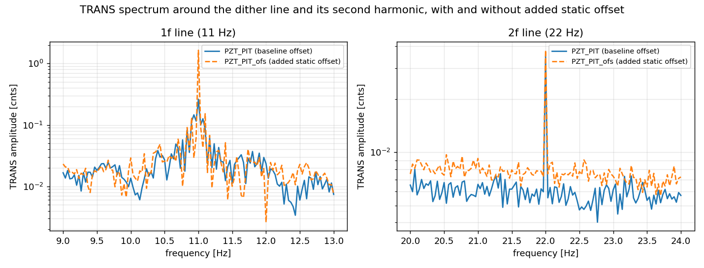
The static offset drops out of the second harmonic algebraically. 2f therefore delivers |δa| with no reference to the alignment state we happened to be sitting at, and with no external angle standard. The DC and f terms, the two one would reach for first, are both contaminated by it.
This is the whole point of the method, and it is directly visible in the plot. adding a static offset grows the 1f line by +528 % while the 2f line moves by +8 %, its own measurement noise.
I proceeded 4+1 measurement in total with the JAC locked. For each measurement, one actuator axis was dithered at 11 Hz, with the excitation injected on the channels below and the drive read back on the corresponding _OUT. I excited JM1/PZT PIT/YAW per one measurement, and the other one is the PZT_PIT excitation with static offset (30 cnts) to demonstrate that the 2f peak is not affected by the offset. Transmission was read on H1:JAC-TRANS_A_LF_OUT.
| record | excitation channel | drive read back on | amplitude at 11 Hz [cnt] | drive offset [cnt] | TRANS DC [cnt] |
|---|---|---|---|---|---|
PZT_PIT |
H1:JAC-PZT_PIT_EXC |
H1:JAC-PZT_PIT_OUT |
20.0 | 0 | 6451.2 |
PZT_PIT_ofs |
H1:JAC-PZT_PIT_EXC |
H1:JAC-PZT_PIT_OUT |
20.0 | 30 | 6442.5 |
PZT_YAW |
H1:JAC-PZT_YAW_EXC |
H1:JAC-PZT_YAW_OUT |
20.0 | 0 | 6442.6 |
JM1_PIT |
H1:SUS-JM1_M1_TEST_P_EXC |
H1:SUS-JM1_M1_TEST_P_OUT |
40.0 | 0 | 6445.5 |
JM1_YAW |
H1:SUS-JM1_M1_TEST_Y_EXC |
H1:SUS-JM1_M1_TEST_Y_OUT |
40.0 | 0 | 6440.2 |
|δa| is calculated from peak heights of the transmission at 22 Hz, converted to a mirror tilt using the local beam radius at each actuator from the current JAC reflected-path layout model (alog91472 comment), and calibrated into DC responce using each actuator's frequency response as measured (described below).
| actuator | axis | excitation channel | |δa|2 |
efficiency [μrad/cnt] | |
|---|---|---|---|---|---|
| at 11 Hz (as measured) | at DC | ||||
| PZT | PIT | JAC-PZT_PIT_EXC |
1.09e-5 | 0.0093 | 0.083 |
| PZT | YAW | JAC-PZT_YAW_EXC |
6.47e-6 | 0.0093 | 0.079 |
| JM1 | PIT | SUS-JM1_M1_TEST_P_EXC |
1.01e-5 | 0.0216 | 0.89 |
| JM1 | YAW | SUS-JM1_M1_TEST_Y_EXC |
1.67e-5 | 0.0254 | 0.92 |
The 11 Hz column is what the dither actually produced; the DC column is that value divided by the actuator's own response at 11 Hz, and is the number to use for a DC gain.
The frequency response itself comes from a separate set of four broadband actuator-to-wavefront-sensor records (300 s each, one actuator per record, see atatched plots), from which the JM1 suspension resonance and the PZT drive pole are fitted. Only the shape of those transfer functions is used; their absolute scale plays no role in the calibration.
The fitted frequency responses are:
f0 = 2.00 Hz, Q = 7.7 (PIT) and 1.80 Hz, Q = 5.4 (YAW)fp = 1.24 Hz (PIT) and 1.30 Hz (YAW)AOI compensation
Both actuators sit at a design AOI of 45°, and the rows above include the geometric correction that follows. A tilt whose rotation axis lies in the mirror surface and in the plane of incidence steers the beam by only 2θ cos(AOI), against the full 2θ for the axis perpendicular to that plane. At the PZT the suppressed axis is YAW in the cavity-referred channel naming (the HAM1 periscope exchanges the transverse planes downstream of it); JM1 sits after that periscope, so for it the suppressed axis is PIT. The assignments follow from each mirror's orientation, and the correction uses the design 45° rather than a value fitted to the measured ratio.
APZT = 500 μrad/V (T1500342) driven through an 18-bit DAC (±10 V differential, i.e. 20 V over 217 counts) and a differential-to-single-ended board (D1100457 v2, unity gain, read off its schematic), giving 0.076 μrad/cnt. No further driver gain applies on top, since the T1500342 figure is referenced at the controller's control input. Our result sits at 1.09× (PIT) and 1.04× (YAW) of this designed value.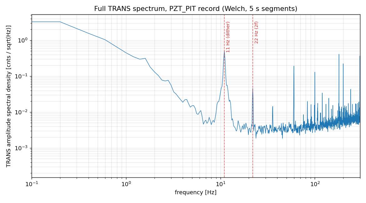

Short note: a mirror rotated by θ, sitting where the beam radius is w(z), produces |δ| = k w(z) θ, and its phase relative to TEM00 is 90° plus the Gouy phase accumulated from the reference waist. This can be applied for the mirror which is transmitting the lens. This is because δ is the field amplitude of the first-order mode it is continuous across lenses, so a mirror separated from the reference space by lenses is handled by simply adding up the free-propagation Gouy phase to the reference waist. The table below therefore carries the beam radius and the accumulated Gouy phase at each actuator.
| actuator | axis | excitation channel | |δa|2 | efficiency [μrad/cnt] | beam radius w [mm] |
Gouy phase from the JAC waist [deg] |
|
|---|---|---|---|---|---|---|---|
| at 11 Hz (as measured) | at DC | ||||||
| PZT | PIT | JAC-PZT_PIT_EXC | 1.09e-5 | 0.0093 | 0.083 | 3.020 | -86.4 |
| PZT | YAW | JAC-PZT_YAW_EXC | 6.47e-6 | 0.0093 | 0.079 | 3.270 | -73.5 |
| JM1 | PIT | SUS-JM1_M1_TEST_P_EXC | 1.01e-5 | 0.0216 | 0.89 | 0.620 | -32.7 |
| JM1 | YAW | SUS-JM1_M1_TEST_Y_EXC | 1.67e-5 | 0.0254 | 0.92 | 0.681 | -30.8 |
The beam radius (1/e2 intensity) and the Gouy phase are model values at the actuator, taken from the JAC REFL optical model.
L.Dartez, S. Dwyer, M. Nakano

Continuing from alog 91450, I started using awg to raster the im4 alignment to find the IR beam on the ISCT1 REFL camera on Friday. This effort was paused at the end of the day without finding the beam. This morning, Masayuki and Sheila noticed that the AS AIR camera had a beam but it was off-center. They walked it back using PR2 and IM4 and adjusted PR3 and the BS to compensate.

When I got in to the control room I adjusted IM4 further to center the beam on ASC-POP_A. ASC-POP_B is still off center but we're choosing to prefer that POP_A stays centered for now.

Later this morning, Masayuki and I decided to see if we could find a PR2 + PR3 + PM1 alignment that 1.) maximizes LSC-POP, 2.) maintains the beam centered on ASC-POP_X, and 3.) maintains the beam center on the ISCT1 REFL camera. Starting from the nominal position (e.g. the position it was already in before we started) we moved PR2 in each direction. Each trial move's procedure was as follows: 1.) move PR2, 2.) compensate with PR3 to recenter ISCT1 REFL camera, 3.) adjust PM1 to center onto POP_X, 4.) observe/record the LSC POP counts.

We currently have roughly 3.4 counts on ASC-POP_X NSUM and 2.7 counts on LSC POP with POP_X centered within about 0.15 and 0.1 counts for PIT and YAW, respectively.

The slider values for PM1 are in PM1_sliders.png and the sliders for PR2,PR3, and IM4 are in IFO_sliders.png.

This new alignment configuration should better position us for the arm peak taking place this week, since we can confirm that we have red beam down to the ISCT1 table and on POP_X. The next intermediate step here will be to lock PRMI...


Masayuki and I aligned PRM. We aren't able to lock PRMI yet since there is no light on LSC POPAIR 18 right now.

Sliders for PRM are in PRM_sliders.png.
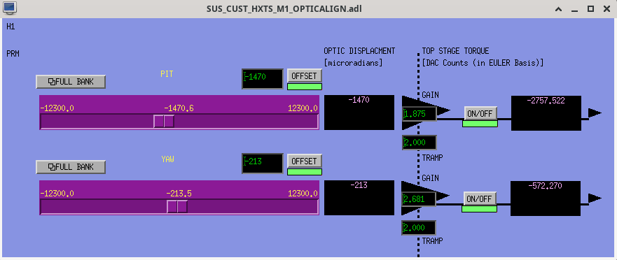
I briefly misaligned the PRM and BS to check the actuation range of the RMs with the DC centering loops engaged to make sure that we aren't at risk of railing them. All looks good.
Jennie Wright, Masayuki Nakano, Khanh Vu

This morning we worked on several tasks on the IOT1 table, including installing the camera and shutter, profiling the beam, and calibrating the DC power.

We identified a new location for the camera using the beam transmitted through JACR_M5. During this process, Masayuki noticed that the beam was being clipped by the shutter. We suspect that the beam may have been clipped for some time. We then installed the camera in its new location, and Masayuki aligned the shutter on the table.

Next, we profiled the beam for the wavefront sensors. We found that the Gouy phase separation between the two WFSs is approximately 70 degrees. We decided to leave the current configuration as it is since the separation is good enough. Masayuki will make a plot and perform a more detailed calculation later.

We also maximized the laser power in the REFL path by optimizing the waveplate angle. When JAC is unlocked, the measured power on the RFPD is 5.1 mW, and the trigger PD voltage is 0.28 V. When JAC is locked, the measured power decreases to 0.4 mW, and the trigger PD voltage is 0.02 V. Since the beam is split evenly, each WFS receives approximately 2.55 mW of optical power.

Finally, we calibrated the DC readout of RFPD by converting counts to mW. Before performing the calibration, Masayuki checked the alignment and recentered the RFPD. He then recorded two sets of measurements, each averaged over 10 seconds:

Measurement #1

* JAC_REFL_A_LF_INMON: 1072.3966186523437 counts
* DC power: 4.4 mW

Measurement #2

* JAC_REFL_A_LF_INMON: 1073.5228637 counts
* DC power: 4.5 mW

After the calibration, we updated filter number 10 with the new coefficients.
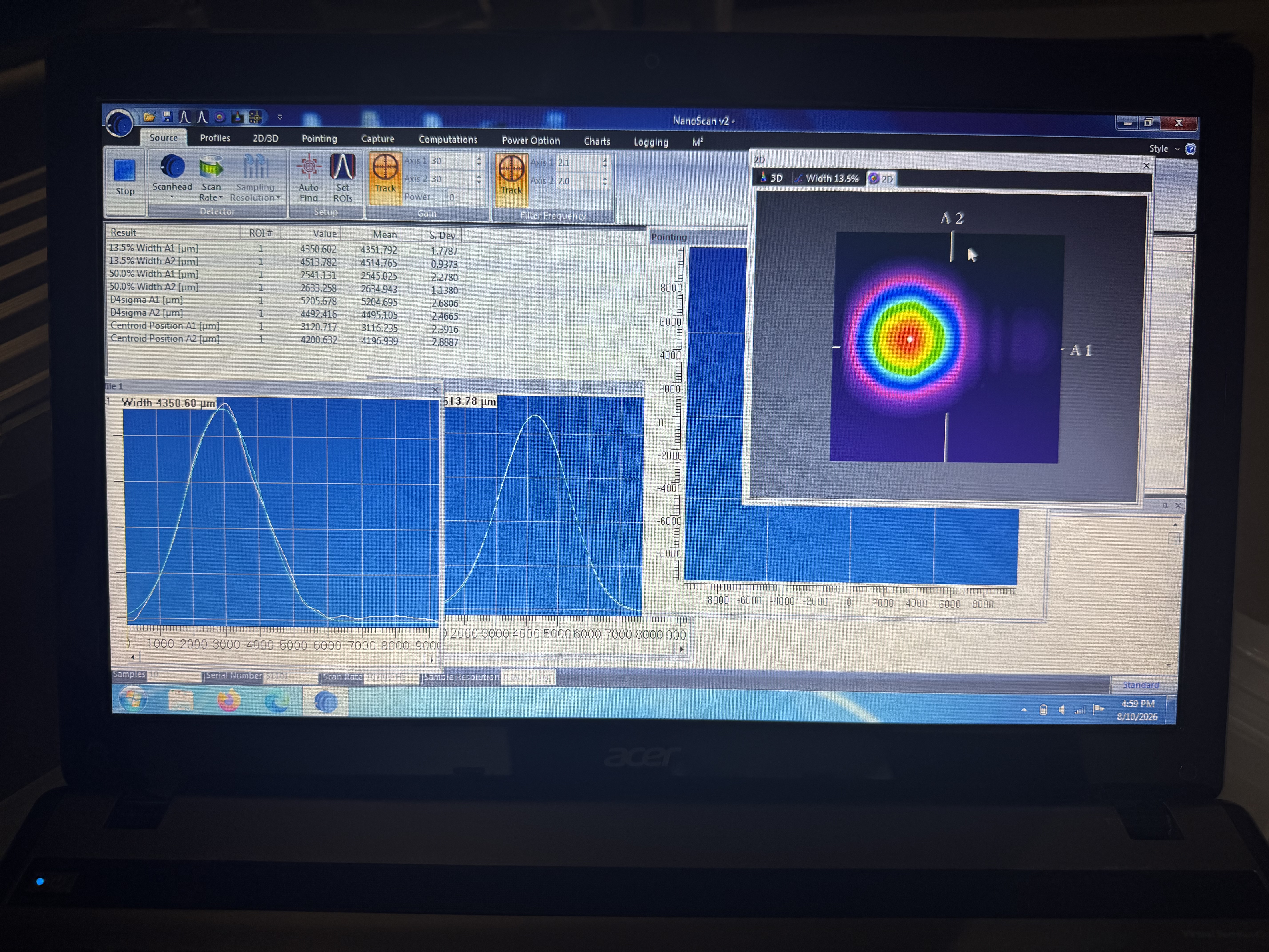
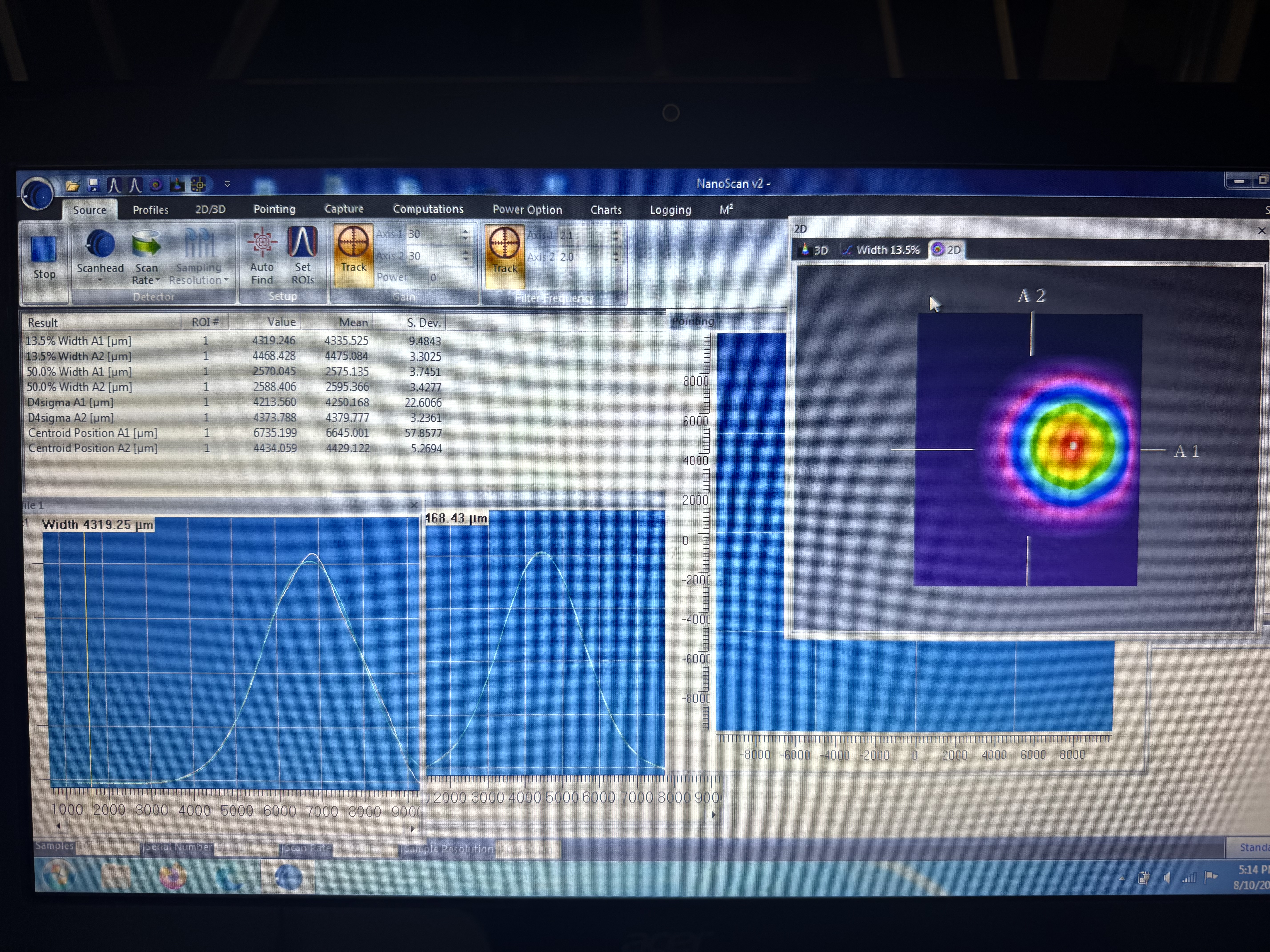
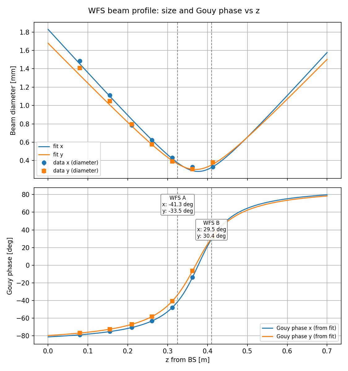
The beam profile between the beamsplitter and the JAC WFS was measured. Here I fit a Gaussian beam to those measured beam sizes and convert the WFS locations into Gouy phase.
The measured beam diameters were fit independently in x and y with the standard Gaussian beam model, w(z) = w0 * sqrt(1 + ((z - z0)/zR)^2) with zR = pi * w0^2 / lambda and lambda = 1064 nm:
| w0 [um] | z0 [m from JACR_BS4] | zR [cm] | |
|---|---|---|---|
| x | 141.2 | 0.377 | 5.89 |
| y | 151.9 | 0.370 | 6.81 |
The beam is slightly astigmatic, so x and y are treated separately throughout.
The positions of WFS A and WFS B were measured with a ruler from the same reference as the profile scan: WFS A at z = 0.325 m, WFS B at z = 0.410 m. The corresponding Gouy phases, psi(z) = arctan((z - z0)/zR), are:
| WFS A [deg] | WFS B [deg] | Separation [deg] | |
|---|---|---|---|
| x | -41.3 | +29.5 | 70.8 |
| y | -33.5 | +30.4 | 63.9 |
The separation is 71 deg in x and 64 deg in y, not the optimal 90 deg. This is not optimal, but it is not terrible either: the two WFS remain well separated in Gouy phase and the sensing matrix would not be close to degenerate. Given the time available we did not optimize the layout.
If we want to optimize it later, the fix is straightforward: moving WFS A upstream (toward the BS) by about 5 cm in x / 7 cm in y, i.e. from z = 0.325 m to roughly z = 0.27 m, brings the separation to 90 deg. WFS B does not need to move.
Additional context for the work described above: The motivation for the table work came from the difficulties we had with the sensing and input matrices of the JAC ASC loops. In pitch, the PZT and JM1 signals are well separated, but their responses in yaw are too similar. This is problematic because we need the two wavefront sensors to distinguish between the motions of the two actuators.

While identifying a new location for the camera, Masayuki noticed that the shutter was clipping approximately half of the beam on the left side. We suspect that the beam may have been clipped for some time and that this may be related to the yaw issue, since the clipping affects yaw more strongly than pitch.
Today we installed the iris to block the ghost beam on the JAC REFL path with an iris, and to re-measure the beam profile with it in place. The ghost beam was produced by the laser window which picks off the partial power of the JAC reflection beam (~0.4%). Since this laser window doesn't have the wedge on it, the AR reflection is not well separated. We observed this interference during the original beam profile measurement in this thread.
And now, the iris dumps the ghost beam, and we made a new the beam profile measurement. I made a good JAC REFL optical model which obtained by the fitting the beam profile measurement. We will use this model for the WFS signal calibration.
An iris was placed on the REFL path, between the first pick-off mirror and the first lens. To position it, the beam profiler was set just after the beam shutter, and the iris was closed while watching the profile, until the ghost was blocked and the main beam was left untouched. Actually, Since the ghost beam is very close, the main beam is partially blocked as shown in the attached pics. We will see if it would have any effect on our WFS signals.
1/e2 diameters along the REFL path, with JACR_MB4 as the origin:
| z [inch from JACR_MB4] | -21 | 3.5 | 5.5 | 7.5 | 9.5 | 11.5 |
|---|---|---|---|---|---|---|
| horizontal [μm] | 4440 | 1360 | 1140 | 895 | 696 | 500 |
| vertical [μm] | 4540 | 1360 | 1111 | 873 | 661 | 461 |
On-table distances were also measured: JACR_L1 to JACR_MB4 = 24", JACR_MB4 to WFS A = 12.5", JACR_MB4 to WFS B = 15.5".
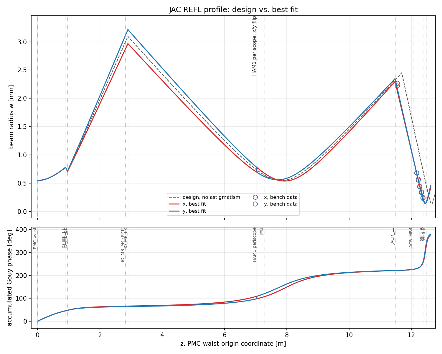
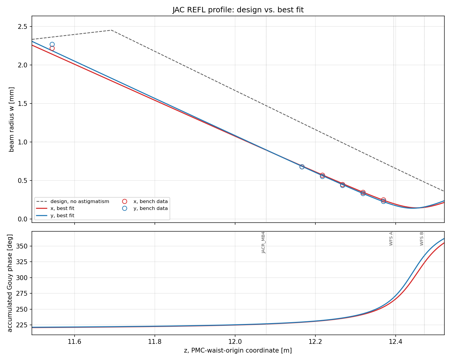
I made a model of the beam propagation of the JAC REFL path from PSL to JAC and IOT1. This model was fitted to the new profile, with the PMC waist as origin.
Taken as known. The positions of lenses in PSL (IO_MB_L1/L2/L3) and of the JAC waist are the design values, i.e. the PSL bench to HAM1 relative distance is trusted.
Taken as unknown. The design placed the IOT1 table only loosely, and the periscope that matches the HAM1 beam height to the table height was estimated roughly. The distance from the JAC input to the IOT1 table is therefore the principal free parameter, allowed ±30 cm; it enters the calculation as the position of JACR_L1 measured from the PMC waist. The profile measurement was referenced to JACR_MB4, which carries its own error, so the JACR_MB4-JACR_L1 distance is a second free parameter.
The profile carries astigmatism, so a yaw tilt was allowed on each of the four lenses (three on the PSL bench, one on IOT1). This is deliberately over-parameterised: the individual tilts should not be read as physical alignment errors. However, the aim of this analysis is not to measure how each lens sits but a model accurate enough for the following calculation. So as long as the aquired prameters are physically reasonable, we can use these numbers as the following calculations.
One note:
The HAM1 periscope (JAC_M1/JAC_M2) rotates the beam 90 degrees about its axis, so the transverse planes swap on the way to JAC: bench x (YAW) descends from the upstream sagittal channel and bench y (PIT) from the tangential one. A tilt therefore gives astigmatism of opposite sign depending on which side of the periscope the lens sits. This is the reason why the x/y beam size flipped at periscope in the attached plot.
| parameter | fitted | vs design |
|---|---|---|
| JACR_L1 position from PMC waist | 11.4768 m | -21.5 cm |
| JACR_MB4 to JACR_L1 | 0.6004 m | -0.36" |
| yaw tilt, IO_MB_L1 / L2 / L3 | -16.9° / -7.1° / -1.8° | - |
| yaw tilt, JACR_L1 | -3.2° | - |
The fitted path from the JAC input to the IOT1 table comes out about 21.5 cm shorter than design, which is the scale of looseness that was expected there.
Astigmatism at the WFS planes
Expressed as the difference in accumulated Gouy phase between the two transverse axes:
| model | from the measured profile alone | |
|---|---|---|
| WFS A | -4.10° | -4.96° |
| WFS B | -10.61° | -10.32° |
Taking the cavity eigenmode as the reference, the fitted injection-lens tilts imply a mismatch of 0.48 % (tangential) and 0.43 % (sagittal), 0.91 % combined. Small enough not to conflict with the measured mode matching (~1%).
PMC eigen mode
| axis | w0 [μm] | zR [mm] |
|---|---|---|
| tangential (u) | 546.312 | 881.232 |
| sagittal (v) | 549.028 | 890.016 |
The waist sits at z = 0 in both axes. Downstream of the periscope the tangential channel becomes bench y (PIT) and the sagittal channel bench x (YAW).
z is given from the PMC waist (the model's own origin) and from JACR_MB4 (the origin the bench profile was measured against).
| element | z from PMC waist [m] | yaw tilt [deg] | source |
|---|---|---|---|
| PMC waist | 0.000000 | - | origin |
| IO_MB_L1 | 0.900000 | -16.86 | design / tilt fitted |
| IO_MB_L2 | 0.960000 | -7.12 | design / tilt fitted |
| IO_MB_M4 (PZT) | 2.812000 | - | design |
| IO_MB_L3 | 2.900000 | -1.75 | design / tilt fitted |
| HAM1 periscope (JAC_M2) | 7.040000 | - | design; x/y swap |
| JM1 | 7.268000 | - | design |
| JAC input mirror | 7.576000 | - | design |
| JAC waist | 7.826000 | - | design |
| JACR_L1 | 11.476799 | -3.15 | fitted |
| JACR_MB4 | 12.077174 | - | fitted (via JACR_L1 distance) |
| WFS A | 12.394674 | - | measured from JACR_MB4 |
| WFS B | 12.470874 | - | measured from JACR_MB4 |
| parameter | fitted value | design | allowed range |
|---|---|---|---|
| JACR_L1 from PMC waist | 11.476799 m | 11.691967 m | ±30 cm |
| JACR_L1 to JACR_MB4 | 0.600375 m | 0.609600 m | ±1" |
| yaw tilt, IO_MB_L1 | -16.8588° | 0 | ±20° |
| yaw tilt, IO_MB_L2 | -7.1210° | 0 | ±20° |
| yaw tilt, IO_MB_L3 | -1.7534° | 0 | ±20° |
| yaw tilt, JACR_L1 | -3.1527° | 0 | ±20° |