[Jason, Jennie, Betsy, Keita, Sophie, Masayuki]
Initial alignment (1/8)
-
For the initial JAC alignment, we need to scan with laser frequency since we didn't have JAC PZT actuation. The laser frequency was swept by changing the laser crystal temperature from −0.13 K to −0.05 K with a period of 30 seconds.
-
The alignment was adjusted to suppress higher-order modes resonance. The actuators used were the PSL PZT and the fixed Siskiyou-mounted mirror that replaced the JM1 tip-tilt suspension. I worked inside the chamber while Jason controlled the PSL PZT via MEDM. Beam walking was performed by moving the PSL PZT first and optimizing alignment with the other mirror in the chamber. Note that due to the HAM1 periscope rotating the beam axis by 90 degrees, the pitch and yaw of the PSL PZT are effectively swapped in the JAC coordinate basis.
-
As a result, moving the PSL PZT by approximately 1000 counts in pitch (corresponding to yaw in the JAC basis) achieved an alignment good enough to observe the TEM_{00} mode. Further alignment will be performed using the transmission PD signal.
JAC wiring (1/8)
-
After discussion, we decided to delay installation of the reflection path. Since PDH locking using the reflection RF PD was therefore unavailable, we proceeded to align the TRANS DC PD and aim for shoulder locking using this signal.
-
In the nominal design, the TRANS PD receives light from the JAC leak port (~0.3% of the input power), picked off by a laser window with 0.7% reflectivity. However, with the current PSL power of ~100 mW, the available light was insufficient. Therefore, the TRANS PD was configured to directly receive light from the leak port without a laser window.
-
Due to a mistake, a post that was 0.5″ too short was prepared for the DC PD mount, and no suitable replacement was readily available. As a temporary configuration, the PD was mounted in a base–dog clamp–post–dog clamp–PD stack, using a 0.25″-thick dog clamp as a spacer.
-
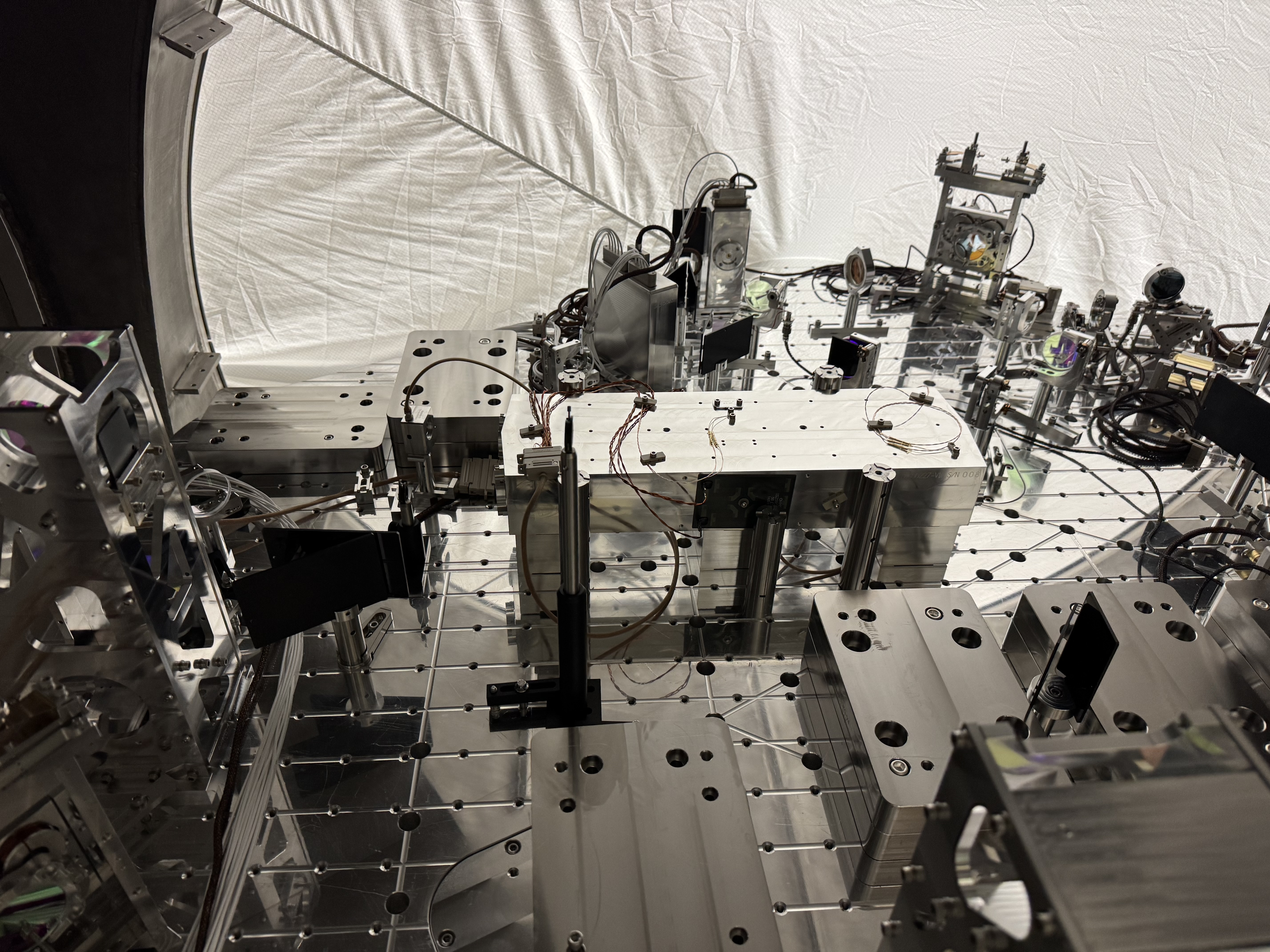
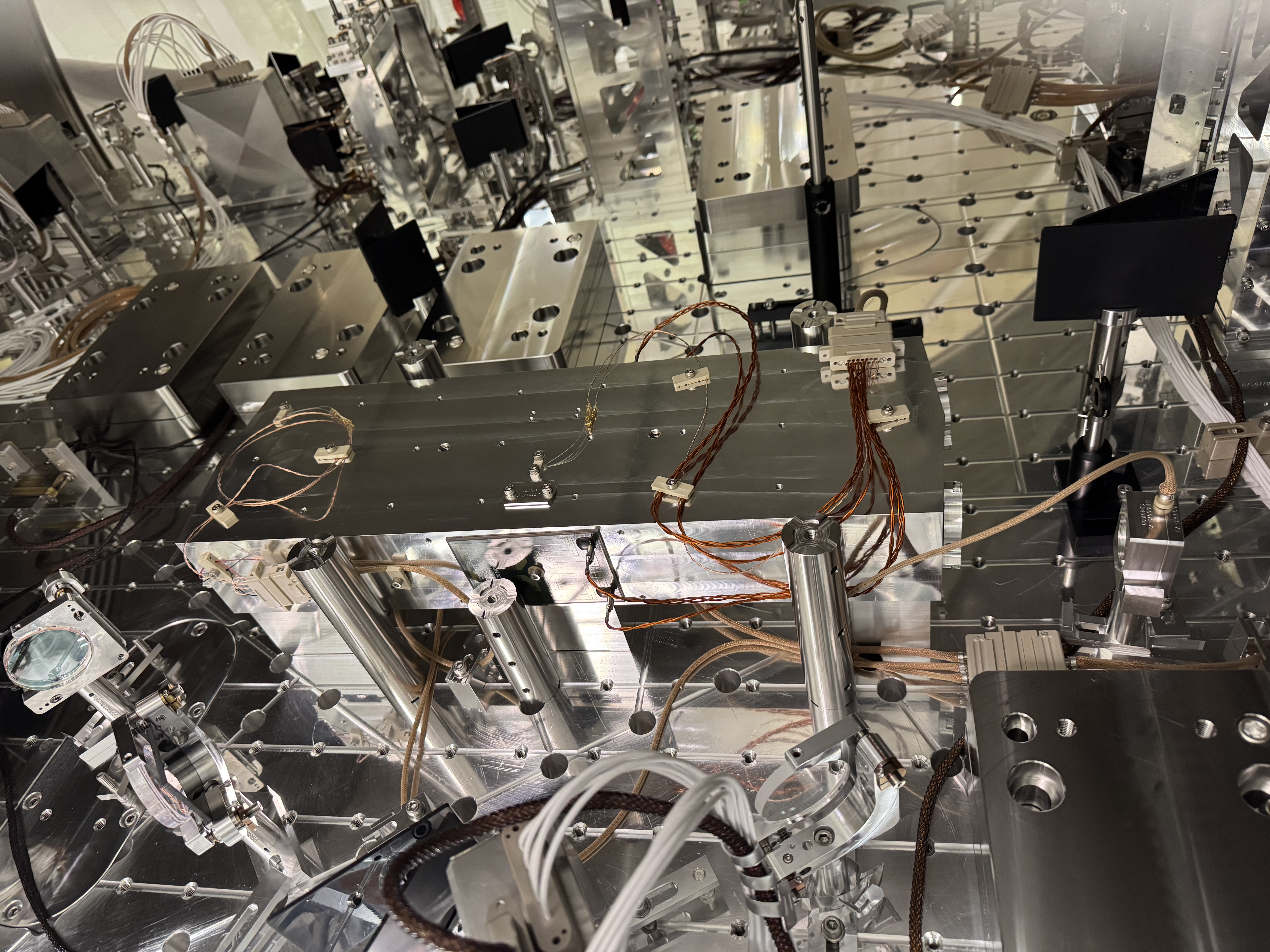
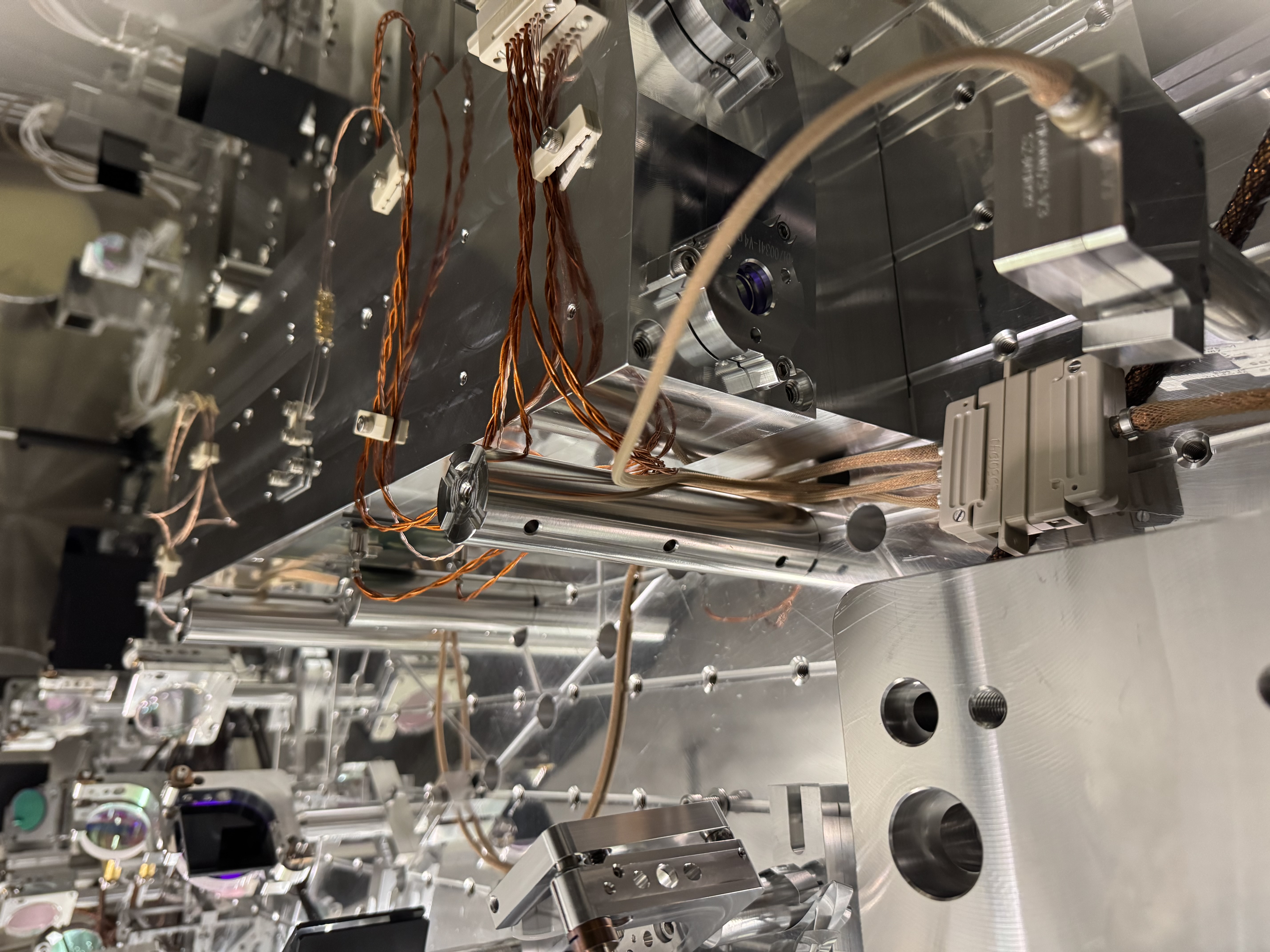
In-vacuum cables were also wired. From the feedthrough (D4F10), a DB25 cable (D2500336) splits into three branches: TRANS PD, PZT & thermistor, and heater & thermistor. Since the ALS beam runs adjacent to the JAC, cable routing clamps were used to avoid interference with the ALS beam (see attached photos).
Wiring confirmation (1/9)
-
To enable locking using the TRANS PD, we confirmed that the corresponding signal path exists in the CDS infrastructure added by Daniel. In the H1LSC model, ADC2 channel 10 is assigned to the DC PD and routed through the dither locking module to the JAC PZT output.
-
In the analog path, the DCPD output from the JAC interface chassis is connected to the auxiliary PD concentrator, and its monitor port is routed to the DAC via the D-sub patch panel. Both the fast and slow channels were confirmed to be correctly connected using the actual PD signal.
-
The polarity of the PZT wiring was verified. For this test, the DB9 connector of the PZT & thermistor cable (D2500336) on the JAC side was disconnected, and gold pins were inserted into pins 5 and 9 of the feedthrough-side female connector (the PZT inputs). A 100-count offset was applied to the JAC_SERVO filter bank output driving the PZT, and the voltage between pins 5 and 9 was measured with a multimeter. To avoid high voltage during this test, the HV amplifier was powered by an 18 V supply instead of the nominal HV source.
-
Toggling the 100-count offset resulted in −10 V (off) and +9 V (on). The same behavior was observed when measuring the PZT driver output directly, confirming correct cable connections and no risk of reverse loading the PZT.
-
These voltage levels were not considered reasonable for normal operation, so Daniel was consulted. The likely explanation was operation with the 18 V supply instead of the HV source. After reconnecting the HV supply, injecting the laser into the JAC, and applying a ramp signal to the PZT, motion of the PZT was clearly observed in the transmission signal.
-
The TRANS PD was re-aligned, and the signal observed on MEDM was maximized.
-
The thermistor connection was also verified, yielding a reasonable reading of approximately 22 °C. Heater testing has not yet been performed, but functionality of the PZT, thermistor, and PD has now been confirmed.
Optics preparation (1/9)
-
In parallel with wiring checks, preparation of the optics on the JAC output side was carried out.
-
An issue was found with a newly fabricated ISC post (8-32 variant) intended for the lens mounts; it was confirmed that the standard D1000968 post works without issue. Keita and Sheila located suitable posts in the staging building, and three lens mounts were assembled using these posts.
-
Attempts to peel the First Contact from the lenses were unsuccessful, as the FC layer was extremely difficult to remove, and we gave up. Applying FC to spare optics is considered the fastest path forward, and for the stuck FC, reapplying FC to soften it may be necessary.
-
HR mirror preparation was also performed.
-
Further details of the optics preparation will be posted shortly by Keita.
Mirrors inspected:
| Mirror | status | was found | what was done |
| M2 | Not ready | in a lens container with foam sponge after the first cotnact was removed, which is a bad idea. Many dust particles after taking it out of the box. | Painted first contact. |
| M3 | Ready | Was in the chamber, first contact still on. | Removed FC while using top gun. A big dust particle in the back surface, couldn't remove with further top gun, but that's OK. |
| RM3 | Not ready | Was in the chamber, first contact still on. | Removed FC while using top gun. One dust particle close to the center, couldn't remove. Painted FC. |
M3 assy is in the chamber (but is still at the edge of the ISI).
M2 and RM3 optics are stored outside of the chamber.
Lens First Contact problem:
All of the lenses had at least one surface where the first contact was incredibly strongly attached. Simple pulling of the mesh won't do anything even with serious force. We wiggled the mesh in multiple directions with enormous force and the mesh started separating from the FC. Will discuss with Betsy on Monday. All of these are stored outside of the chamber.
| L1 | FC remains on one surface. Painted FC on top of the existing layer over the mesh. Will see if it makes the FC loose. |
| L2 | FC remains on both surfaces. |
| L3 | FC remains on one surface. |
2" Lens Post issue:
All pieces of 8-32 variant of D1000968-v3 were manufactured incorrectly, they have 8-32 bottom screw holes so cannot be mounted on the standard ISC baseplate.
To make them usable, the bottom hole should be widened and re-tapped for 1/4-20 though there's no urgency because we were able to use the original 1/4-20 version. (It seems that this variant was requested on a wrong assumption that Siskiyou lens mount only accepts 8-32. In reality the lens mount has two screw holes, one for 8-32 and the other for 1/4-20, so this variant isn't really needed.)
Tagging for EPO photos